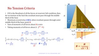
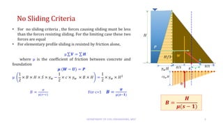
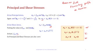
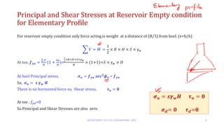
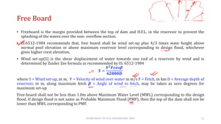
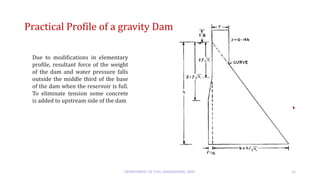
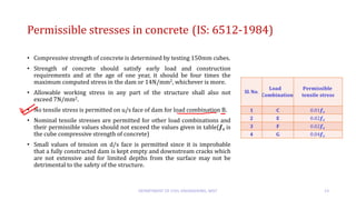
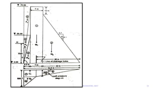
GRAVITY DAM-
ELEMENTARY PROFILE
SUSMITA BAKSHI
Introduction
DEPARTMENT OF CIVIL ENGINEERING, MSIT 2
• Elementary Profile of a Gravity Dam consists of the
basic triangular dam section without any top width
and no free board
• Three forces weight of the dam, water pressure of
reservoir water and uplift are the only forces present
• This hypothetical profile provides the maximum
stability of the dam – without any tension during
reservoir empty condition
• Base width for elementary profile is found from no
tension and no sliding criteria and the higher of the
two is adopted.
Forces acting
• Self Weight of Dam, W
𝑾 =
𝟏
𝟐
× 𝑩 × 𝑯 × 𝑺 × 𝜸𝒘
Acting vertically downward at the centroid of the triangular area at (B/3) from heel
• Water Pressure, P
𝑷 =
𝟏
𝟐
× 𝜸𝒘 × 𝑯𝟐
Acting horizontally at (H/3) from base
• Uplift Pressure, U
𝑼 =
𝟏
𝟐
× 𝒄 × 𝜸𝒘 × 𝑩 × 𝑯
Acting vertically upward at the centroid of the triangular area at (B/3) from heel
DEPARTMENT OF CIVIL ENGINEERING, MSIT 3
No Tension Criteria
DEPARTMENT OF CIVIL ENGINEERING, MSIT 4
• If R is the Resultant of all the forces at reservoir full condition, then
for no tension at the heel the resultant must pass through the middle
third of the base
• Maximum eccentricity e=B/6, when resultant passes through outer
middle third of the base, point A
• Sum of moments of all forces about A is zero
• Taking moments of all forces about A (↶ +)
𝑊 ×
𝐵
3
− 𝑈 ×
𝐵
3
− 𝑃 ×
𝐻
3
= 0
1
2
× 𝐵 × 𝐻 × 𝑆 × 𝛾𝑤 ×
𝐵
3
−
1
2
× 𝑐 × 𝛾𝑤 × 𝐵 × 𝐻 ×
𝐵
3
−
1
2
× 𝛾𝑤 × 𝐻2
×
𝐻
3
= 0
𝐵 =
𝐻
𝑠−𝑐
For c=1 𝑩 =
𝑯
𝒔−𝟏
𝑩 =
𝑯
𝒔 − 𝟏
No Sliding Criteria
DEPARTMENT OF CIVIL ENGINEERING, MSIT 5
• For no sliding criteria , the forces causing sliding must be less
than the forces resisting sliding. For the limiting case these two
forces are equal
• For elementary profile sliding is resisted by friction alone,
μ σ 𝑽 = σ 𝑯
where μ is the coefficient of friction between concrete and
foundation
𝝁 (𝑾 − 𝑼) = 𝑷
μ
1
2
× 𝐵 × 𝐻 × 𝑆 × 𝛾𝑤 −
1
2
× 𝑐 × 𝛾𝑤 × 𝐵 × 𝐻 =
1
2
× 𝛾𝑤 × 𝐻2
𝐵 =
𝐻
μ(𝑠−𝑐)
For c=1 𝑩 =
𝑯
μ(𝒔−𝟏)
𝑩 =
𝑯
𝝁(𝒔 − 𝟏)
Stresses at Reservoir Full condition for Elementary Profile
• The vertical stress distribution at the upstream and downstream edge of the base of the dam is given by
𝒇𝒚 =
σ 𝑉
𝐵
(1 ±
6𝑒
𝐵
)
• For reservoir full condition, maximum stress occurs at toe and minimum stress at heel. For reservoir
empty condition situation is reverse
• In elementary profile resultant passes through (B/3) from toe . So e=B/6
• Minimum stress at heel =0, Maximum stress at toe =
2 σ 𝑉
𝐵
σ 𝑉 = 𝑊 − 𝑈 =
1
2
× 𝐵 × 𝐻 × 𝑆 × 𝛾𝑤 −
1
2
× 𝑐 × 𝛾𝑤 × 𝐻 𝑋 𝐵 =
1
2
× 𝐵 × 𝐻 × 𝛾𝑤 × (𝑆 − c)
At toe, 𝒇𝒚𝒅 =
σ 𝑉
𝐵
(1 +
6𝑒
𝐵
)= 𝛾𝑤 × 𝐻 × (𝑆 − c)
At heel, 𝑓𝑦𝑢=0
DEPARTMENT OF CIVIL ENGINEERING, MSIT 6
𝒇𝒚𝒖= 0
𝒇𝒚𝒅 = 𝜸𝒘 𝑯(𝑺 − 𝐜)
Principal and Shear Stresses
At toe Principal stress, 𝝈𝒅 = 𝒇𝒚𝒅 𝒔𝒆𝒄𝟐
𝝓𝒅 = 𝛾𝑤 × 𝐻 × (𝑆 − c) 𝒔𝒆𝒄𝟐
𝝓𝒅
Again 𝒔𝒆𝒄𝟐
𝝓𝒅 = 1 + (
𝐵
𝐻
)2
and 𝐵 =
𝐻
𝑠−𝑐
So, 𝝈𝒅 = 𝜸𝒘 𝑯(𝑺 − 𝐜 + 𝟏)
At toe Shear stress, 𝝉𝒅 = 𝒇𝒚𝒅 𝒕𝒂𝒏𝝓𝒅
Putting the value of 𝒇𝒚𝒅 and 𝒕𝒂𝒏𝝓𝒅
𝝉𝒅 = 𝛾𝑤 𝐻 𝑠 − 𝑐
At heel , 𝑓𝑦𝑢=0
So Principal and Shear Stresses are also zero
DEPARTMENT OF CIVIL ENGINEERING, MSIT 7
𝝈𝒅 = 𝜸𝒘 𝑯 𝑺 − 𝒄 + 𝟏
𝝉𝒅= 𝜸𝒘 𝑯 𝒔 − 𝒄
𝝈𝒖= 𝟎 𝝉𝒖=0
Principal and Shear Stresses at Reservoir Empty condition
for Elementary Profile
For reservoir empty condition only force acting is weight at a distance of (B/3) from heel. (e=b/6)
෍ 𝑉 = 𝑊 =
1
2
× 𝐵 × 𝐻 × 𝑆 × 𝛾𝑤
At toe, 𝒇𝒚𝒖 =
σ 𝑉
𝐵
(1 +
6𝑒
𝐵
)=
1
2
×𝐵×𝐻×𝑆×𝛾𝑤
𝐵
× (1+1)=𝑆 × 𝛾𝑤 × 𝐻
At heel Principal stress, 𝝈𝒖 = 𝒇𝒚𝒖 𝒔𝒆𝒄𝟐
𝝓𝒖 = 𝒇𝒚𝒖
So, 𝝈𝒖 = 𝒔 𝜸𝒘 𝑯
There is no horizontal force so, Shear stress, 𝝉𝒖 = 𝟎
At toe , 𝑓𝑦𝑑=0
So Principal and Shear Stresses are also zero
DEPARTMENT OF CIVIL ENGINEERING, MSIT 8
𝝈𝒖 = 𝒔𝜸𝒘𝑯 𝝉𝒖 = 𝟎
𝝈𝒅= 𝟎 𝝉𝒅=0
Limiting Height of Gravity Dam
• The maximum value of principal stress should not exceed
the allowable stress for the material
• In the limiting case 𝝈𝒅 = 𝜸𝒘 𝑯(𝑺 − 𝐜 + 𝟏)
• For finding the limiting height, excluding uplift
𝑯𝒍𝒊𝒎 =
𝝈𝒑𝒆𝒓𝒎𝒊𝒔𝒔𝒊𝒃𝒆
𝒔 − 𝟏
• For a concrete dam, s=2.4, 𝝈𝒑𝒆𝒓𝒎𝒊𝒔𝒔𝒊𝒃𝒆= 3𝑁/𝑚𝑚2
, the
limiting height is about 88 m.
• If the height of the dam to be constructed is more than that
𝑯𝒍𝒊𝒎 , the dam is known as high gravity dam. Extra slopes
are given to the u/s and d/s sides, below the limiting height,
to bring compressive stress within permissible limit.
DEPARTMENT OF CIVIL ENGINEERING, MSIT 9
Modifications of elementary profile
DEPARTMENT OF CIVIL ENGINEERING, MSIT 10
Elementary profile of a gravity dam is
not practical or the most economical
section. It is only a theoretical profile.
Following modifications are required in
the form of provision of
(i) top width
(ii) freeboard.
Top width must be provided to resist
forces due to accidental loading and
impact of floating debris. Also a
roadway is usually provided for which a
minimum width of 6 to 7m is
recommended.
Free Board
• Freeboard is the margin provided between the top of dam and H.F.L. in the reservoir to prevent the
splashing of the waves over the non- overflow section.
• IS:6512-1984 recommends that, free board shall be wind set-up plus 4/3 times wave height above
normal pool elevation or above maximum reservoir level corresponding to design flood, whichever
gives higher crest elevation.
• Wind set-up(S) is the shear displacement of water towards one end of a reservoir by wind and is
determined by Zuider Zee formula as recommended by IS: 6512-1984
𝑺 =
𝑽𝟐
𝑭𝒄𝒐𝒔𝜷
𝟔𝟐𝟎𝟎𝟎𝑫
where S = Wind set-up, in m, V = Velocity of wind over water in m/s F = Fetch, in km D = Average depth of
reservoir, in m, along maximum fetch 𝜷 = Angle of wind to fetch, may be taken as zero degrees for
maximum set-up
Free-board shall not be less than 1.0m above Maximum Water Level (MWL) corresponding to the design
flood. If design flood is not same as Probable Maximum Flood (PMF), then the top of the dam shall not be
lower than MWL corresponding to PMF.
DEPARTMENT OF CIVIL ENGINEERING, MSIT 11
Practical Profile of a gravity Dam
DEPARTMENT OF CIVIL ENGINEERING, MSIT 12
Due to modifications in elementary
profile, resultant force of the weight
of the dam and water pressure falls
outside the middle third of the base
of the dam when the reservoir is full.
To eliminate tension some concrete
is added to upstream side of the dam
Permissible stresses in concrete (IS: 6512-1984)
• Compressive strength of concrete is determined by testing 150mm cubes.
• Strength of concrete should satisfy early load and construction
requirements and at the age of one year, it should be four times the
maximum computed stress in the dam or 14N/mm2, whichever is more.
• Allowable working stress in any part of the structure shall also not
exceed 7N/mm2.
• No tensile stress is permitted on u/s face of dam for load combination B.
• Nominal tensile stresses are permitted for other load combinations and
their permissible values should not exceed the values given in table(𝒇𝒄 is
the cube compressive strength of concrete)
• Small values of tension on d/s face is permitted since it is improbable
that a fully constructed dam is kept empty and downstream cracks which
are not extensive and for limited depths from the surface may not be
detrimental to the safety of the structure.
DEPARTMENT OF CIVIL ENGINEERING, MSIT 13
𝐒𝐥. 𝐍𝐨.
𝐋𝐨𝐚𝐝
𝐂𝐨𝐦𝐛𝐢𝐧𝐚𝐭𝐢𝐨𝐧
𝐏𝐞𝐫𝐦𝐢𝐬𝐬𝐢𝐛𝐥𝐞
𝐭𝐞𝐧𝐬𝐢𝐥𝐞 𝐬𝐭𝐫𝐞𝐬𝐬
1 C 0.01𝒇𝒄
2 E 0.02𝒇𝒄
3 F 0.02𝒇𝒄
4 G 0.04𝒇𝒄
DEPARTMENT OF CIVIL ENGINEERING, MSIT 14

gravity dam elementary profile.pdf

  • 1.
  • 2.
    Introduction DEPARTMENT OF CIVILENGINEERING, MSIT 2 • Elementary Profile of a Gravity Dam consists of the basic triangular dam section without any top width and no free board • Three forces weight of the dam, water pressure of reservoir water and uplift are the only forces present • This hypothetical profile provides the maximum stability of the dam – without any tension during reservoir empty condition • Base width for elementary profile is found from no tension and no sliding criteria and the higher of the two is adopted.
  • 3.
    Forces acting • SelfWeight of Dam, W 𝑾 = 𝟏 𝟐 × 𝑩 × 𝑯 × 𝑺 × 𝜸𝒘 Acting vertically downward at the centroid of the triangular area at (B/3) from heel • Water Pressure, P 𝑷 = 𝟏 𝟐 × 𝜸𝒘 × 𝑯𝟐 Acting horizontally at (H/3) from base • Uplift Pressure, U 𝑼 = 𝟏 𝟐 × 𝒄 × 𝜸𝒘 × 𝑩 × 𝑯 Acting vertically upward at the centroid of the triangular area at (B/3) from heel DEPARTMENT OF CIVIL ENGINEERING, MSIT 3
  • 4.
    No Tension Criteria DEPARTMENTOF CIVIL ENGINEERING, MSIT 4 • If R is the Resultant of all the forces at reservoir full condition, then for no tension at the heel the resultant must pass through the middle third of the base • Maximum eccentricity e=B/6, when resultant passes through outer middle third of the base, point A • Sum of moments of all forces about A is zero • Taking moments of all forces about A (↶ +) 𝑊 × 𝐵 3 − 𝑈 × 𝐵 3 − 𝑃 × 𝐻 3 = 0 1 2 × 𝐵 × 𝐻 × 𝑆 × 𝛾𝑤 × 𝐵 3 − 1 2 × 𝑐 × 𝛾𝑤 × 𝐵 × 𝐻 × 𝐵 3 − 1 2 × 𝛾𝑤 × 𝐻2 × 𝐻 3 = 0 𝐵 = 𝐻 𝑠−𝑐 For c=1 𝑩 = 𝑯 𝒔−𝟏 𝑩 = 𝑯 𝒔 − 𝟏
  • 5.
    No Sliding Criteria DEPARTMENTOF CIVIL ENGINEERING, MSIT 5 • For no sliding criteria , the forces causing sliding must be less than the forces resisting sliding. For the limiting case these two forces are equal • For elementary profile sliding is resisted by friction alone, μ σ 𝑽 = σ 𝑯 where μ is the coefficient of friction between concrete and foundation 𝝁 (𝑾 − 𝑼) = 𝑷 μ 1 2 × 𝐵 × 𝐻 × 𝑆 × 𝛾𝑤 − 1 2 × 𝑐 × 𝛾𝑤 × 𝐵 × 𝐻 = 1 2 × 𝛾𝑤 × 𝐻2 𝐵 = 𝐻 μ(𝑠−𝑐) For c=1 𝑩 = 𝑯 μ(𝒔−𝟏) 𝑩 = 𝑯 𝝁(𝒔 − 𝟏)
  • 6.
    Stresses at ReservoirFull condition for Elementary Profile • The vertical stress distribution at the upstream and downstream edge of the base of the dam is given by 𝒇𝒚 = σ 𝑉 𝐵 (1 ± 6𝑒 𝐵 ) • For reservoir full condition, maximum stress occurs at toe and minimum stress at heel. For reservoir empty condition situation is reverse • In elementary profile resultant passes through (B/3) from toe . So e=B/6 • Minimum stress at heel =0, Maximum stress at toe = 2 σ 𝑉 𝐵 σ 𝑉 = 𝑊 − 𝑈 = 1 2 × 𝐵 × 𝐻 × 𝑆 × 𝛾𝑤 − 1 2 × 𝑐 × 𝛾𝑤 × 𝐻 𝑋 𝐵 = 1 2 × 𝐵 × 𝐻 × 𝛾𝑤 × (𝑆 − c) At toe, 𝒇𝒚𝒅 = σ 𝑉 𝐵 (1 + 6𝑒 𝐵 )= 𝛾𝑤 × 𝐻 × (𝑆 − c) At heel, 𝑓𝑦𝑢=0 DEPARTMENT OF CIVIL ENGINEERING, MSIT 6 𝒇𝒚𝒖= 0 𝒇𝒚𝒅 = 𝜸𝒘 𝑯(𝑺 − 𝐜)
  • 7.
    Principal and ShearStresses At toe Principal stress, 𝝈𝒅 = 𝒇𝒚𝒅 𝒔𝒆𝒄𝟐 𝝓𝒅 = 𝛾𝑤 × 𝐻 × (𝑆 − c) 𝒔𝒆𝒄𝟐 𝝓𝒅 Again 𝒔𝒆𝒄𝟐 𝝓𝒅 = 1 + ( 𝐵 𝐻 )2 and 𝐵 = 𝐻 𝑠−𝑐 So, 𝝈𝒅 = 𝜸𝒘 𝑯(𝑺 − 𝐜 + 𝟏) At toe Shear stress, 𝝉𝒅 = 𝒇𝒚𝒅 𝒕𝒂𝒏𝝓𝒅 Putting the value of 𝒇𝒚𝒅 and 𝒕𝒂𝒏𝝓𝒅 𝝉𝒅 = 𝛾𝑤 𝐻 𝑠 − 𝑐 At heel , 𝑓𝑦𝑢=0 So Principal and Shear Stresses are also zero DEPARTMENT OF CIVIL ENGINEERING, MSIT 7 𝝈𝒅 = 𝜸𝒘 𝑯 𝑺 − 𝒄 + 𝟏 𝝉𝒅= 𝜸𝒘 𝑯 𝒔 − 𝒄 𝝈𝒖= 𝟎 𝝉𝒖=0
  • 8.
    Principal and ShearStresses at Reservoir Empty condition for Elementary Profile For reservoir empty condition only force acting is weight at a distance of (B/3) from heel. (e=b/6) ෍ 𝑉 = 𝑊 = 1 2 × 𝐵 × 𝐻 × 𝑆 × 𝛾𝑤 At toe, 𝒇𝒚𝒖 = σ 𝑉 𝐵 (1 + 6𝑒 𝐵 )= 1 2 ×𝐵×𝐻×𝑆×𝛾𝑤 𝐵 × (1+1)=𝑆 × 𝛾𝑤 × 𝐻 At heel Principal stress, 𝝈𝒖 = 𝒇𝒚𝒖 𝒔𝒆𝒄𝟐 𝝓𝒖 = 𝒇𝒚𝒖 So, 𝝈𝒖 = 𝒔 𝜸𝒘 𝑯 There is no horizontal force so, Shear stress, 𝝉𝒖 = 𝟎 At toe , 𝑓𝑦𝑑=0 So Principal and Shear Stresses are also zero DEPARTMENT OF CIVIL ENGINEERING, MSIT 8 𝝈𝒖 = 𝒔𝜸𝒘𝑯 𝝉𝒖 = 𝟎 𝝈𝒅= 𝟎 𝝉𝒅=0
  • 9.
    Limiting Height ofGravity Dam • The maximum value of principal stress should not exceed the allowable stress for the material • In the limiting case 𝝈𝒅 = 𝜸𝒘 𝑯(𝑺 − 𝐜 + 𝟏) • For finding the limiting height, excluding uplift 𝑯𝒍𝒊𝒎 = 𝝈𝒑𝒆𝒓𝒎𝒊𝒔𝒔𝒊𝒃𝒆 𝒔 − 𝟏 • For a concrete dam, s=2.4, 𝝈𝒑𝒆𝒓𝒎𝒊𝒔𝒔𝒊𝒃𝒆= 3𝑁/𝑚𝑚2 , the limiting height is about 88 m. • If the height of the dam to be constructed is more than that 𝑯𝒍𝒊𝒎 , the dam is known as high gravity dam. Extra slopes are given to the u/s and d/s sides, below the limiting height, to bring compressive stress within permissible limit. DEPARTMENT OF CIVIL ENGINEERING, MSIT 9
  • 10.
    Modifications of elementaryprofile DEPARTMENT OF CIVIL ENGINEERING, MSIT 10 Elementary profile of a gravity dam is not practical or the most economical section. It is only a theoretical profile. Following modifications are required in the form of provision of (i) top width (ii) freeboard. Top width must be provided to resist forces due to accidental loading and impact of floating debris. Also a roadway is usually provided for which a minimum width of 6 to 7m is recommended.
  • 11.
    Free Board • Freeboardis the margin provided between the top of dam and H.F.L. in the reservoir to prevent the splashing of the waves over the non- overflow section. • IS:6512-1984 recommends that, free board shall be wind set-up plus 4/3 times wave height above normal pool elevation or above maximum reservoir level corresponding to design flood, whichever gives higher crest elevation. • Wind set-up(S) is the shear displacement of water towards one end of a reservoir by wind and is determined by Zuider Zee formula as recommended by IS: 6512-1984 𝑺 = 𝑽𝟐 𝑭𝒄𝒐𝒔𝜷 𝟔𝟐𝟎𝟎𝟎𝑫 where S = Wind set-up, in m, V = Velocity of wind over water in m/s F = Fetch, in km D = Average depth of reservoir, in m, along maximum fetch 𝜷 = Angle of wind to fetch, may be taken as zero degrees for maximum set-up Free-board shall not be less than 1.0m above Maximum Water Level (MWL) corresponding to the design flood. If design flood is not same as Probable Maximum Flood (PMF), then the top of the dam shall not be lower than MWL corresponding to PMF. DEPARTMENT OF CIVIL ENGINEERING, MSIT 11
  • 12.
    Practical Profile ofa gravity Dam DEPARTMENT OF CIVIL ENGINEERING, MSIT 12 Due to modifications in elementary profile, resultant force of the weight of the dam and water pressure falls outside the middle third of the base of the dam when the reservoir is full. To eliminate tension some concrete is added to upstream side of the dam
  • 13.
    Permissible stresses inconcrete (IS: 6512-1984) • Compressive strength of concrete is determined by testing 150mm cubes. • Strength of concrete should satisfy early load and construction requirements and at the age of one year, it should be four times the maximum computed stress in the dam or 14N/mm2, whichever is more. • Allowable working stress in any part of the structure shall also not exceed 7N/mm2. • No tensile stress is permitted on u/s face of dam for load combination B. • Nominal tensile stresses are permitted for other load combinations and their permissible values should not exceed the values given in table(𝒇𝒄 is the cube compressive strength of concrete) • Small values of tension on d/s face is permitted since it is improbable that a fully constructed dam is kept empty and downstream cracks which are not extensive and for limited depths from the surface may not be detrimental to the safety of the structure. DEPARTMENT OF CIVIL ENGINEERING, MSIT 13 𝐒𝐥. 𝐍𝐨. 𝐋𝐨𝐚𝐝 𝐂𝐨𝐦𝐛𝐢𝐧𝐚𝐭𝐢𝐨𝐧 𝐏𝐞𝐫𝐦𝐢𝐬𝐬𝐢𝐛𝐥𝐞 𝐭𝐞𝐧𝐬𝐢𝐥𝐞 𝐬𝐭𝐫𝐞𝐬𝐬 1 C 0.01𝒇𝒄 2 E 0.02𝒇𝒄 3 F 0.02𝒇𝒄 4 G 0.04𝒇𝒄
  • 14.
    DEPARTMENT OF CIVILENGINEERING, MSIT 14