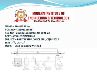
NAME – ABHIJIT SAHA
ROLL NO – 26901321038
REG NO – 212690101320001 OF 2021-22
DEPT – CIVIL ENGINEERING
SUBJECT – PRESTRESSED CONCRETE , CE(PE)702A
SEM -7TH , CA – 1ST
TOPIC – Load Balancing Method
Content
•Load Balancing Method
•Concept of Load Balancing Method
•Life History Of Prestressed Member
•Mechanism & Explanation Of Balanced load
Concept
•ADVANTAGES OF LOAD BALANCING METHOD
•SIMPLE & CANTILEVER BEAM WITH LOAD
BALANCING METHOD
•EXAMPLE PROBLEM OF CANTILEVER BEAM
•Conclusion
•Acknowledgement
Load Balancing Method
3
⚫Load in the concrete is balanced by stressing the steel.
In the overall design of prestressed concrete
structure, the effect of prestressing is viewed as the
balancing of gravity load . This enables the
transformation of a flexural member into a member
underdirect stress and thus greatlysimplifies both the
design and analysisof structure.
⚫ The application of this method requires taking the
concrete as a free bodyand replacing the tendonswith
forces acting on theconcrete along the span.
Concept of Load Balancing Method
4
⚫There are three basic concepts in prestressed concrete
design
1.Stressconcept : Treating prestressed concrete as an
elastic material
2.Strength concept: Considering prestressed concrete as
reinforced concrete dealing with ultimatestrength.
3.Balanced load concept: Balancing a portion of the load
on the structure.
Load Balancing method follows the third one.
Life History Of Prestressed Member
5
⚫ Analysing the life history of the prestressed member
under flexure leads to understanding the balanced load
concept relative toother twoconcept.
⚫So lets find out the load deflection relationshipof a
memberas a simple beam..
⚫K1 = Factorof
safetyapplied to
working load to
obtain minimum
yield point.
⚫K2= Factorof
safetyapplied to
ultimatestrength
design toobtain
minimum ultimate
load.
6
⚫The load deflection relationship of the above figure
leads to several critical points. Such as..
⚫ 1. Pointof nodeflection which indicatesrectangular
stress block.
⚫ 2. Pointof no tensionwhich indicates triangularstress
block with zero stress at the bottom fiber.
⚫
7
3. Pointof cracking which occurswhen the extreme fiber
is stressed to the modulusof rupture.
4.Pointof yielding at which steel is stressed beyond its
yield point so thatcompleterecovery is not possible.
5.Point of ultimate load which represents the
maximum load carried by the memberat failure.
8
Mechanism & Explanation Of Balanced
load Concept
9
According to figure there are three stages of beam
Behavior :
Applied Loadings Stagesof beam behavior
⚫ DL+k3LL ⚫ Nodeflection
⚫ DL+LL ⚫ Notension
⚫ K2(DL+LL) ⚫ Ultimate
⚫ Where,
⚫DL+LL is the stress concept with some allowable
tensionon beam or no tension.
⚫K2(DL+LL) is the strength concept consists with the
ultimate strength of the beam.
⚫DL+K3LL is the balanced load concept with the point
of no deflection where k3 is zero or some value much
less than one.
10
⚫In balanced load conceptdesign isdone by pointof no
deflection.
⚫So prestressing is done in such awayso thateffective
prestress balances the sustained loading & beam
remain perfectly level withoutdeflecting.
11
ADVANTAGES OF LOAD BALANCING METHOD
12
⚫1.simplest approach to prestressed design and
analysis for statically indeterminate structures.
⚫2.It has advantages both in calculating and in
visualizing.
⚫3.Convenience in the computation of deflections.
SIMPLE & CANTILEVER BEAM WITH LOAD
BALANCING METHOD
13
Figure illustrates how to balance a concentrated load
bysharply bending the c.g.s. at midspan , thuscreating
an upward component
V=2Fsinθ
⚫If V exactly balancesaconcentrated load P
Applied at midspan the beam is not subjected toany
transverse load.
The stresses in the beam atany section are simplygiven
by
Any loading addition to P will cause bending and
additional stressescomputed by
14
⚫Figure illustratesthe balancing of a uniformly
distributed load by means of a paraboliccable
whose upward component is given by
15
⚫If the externally applied load w is exactly balanced by
the component Wb there is no bending in the beam.
The beam is again under a uniform compression with
stress
External load produced moment M and corresponding
stresses
16
⚫Figure represents a cantilever beam. Any vertical
component at the cantilever end C will upset the
balance, unless there is an externallyapplied load at
that tip.
17
⚫To balancea uniform load w, the tangent to the c.g.s. at
C will have to be horizontal. Then the parabola for the
cantileverportion can best be located bycomputing
And the parabola for the anchorarm by
18
EXAMPLE PROBLEM OF CANTILEVER BEAM
19
⚫A double cantilever beam is to be designed so that its
prestress will exactly balance the total uniform load of 23.3
KN/m normally carried on the beam. Design the beam
using the least amountof prestress, assuming that the c.g.s
must haveaconcrete protection of at least 76.2mm. If a
concentrated load of 62KN is added at the mid span
compute the maximum top and bottom fiberstresses
SOLUTION:
20
To use the least amountof prestress, theecentricity over the
support should bea maximum that is , h=300mmoro.3m.
The prestress required is F = wL2 / 2h
=(23.3x62)/(2x0.300)=1395KN
Thesag for the parabola must be h1 = w(L1)2/8F
=(23.3x14.82)/(8*1395)
=0.46m
Uniform compressivestress
f= F/Ac = 1395/(2.28x105) = 6.12 Mpa
Moment M at the mid span due to P=62KN
M=PL/4=(62x14.8)/4=229KN-m
Extreme fiberstresses are
f=Mc/I=6M/bd2 = (6x229x106)/(300x7602)
= 7.93MPa
Stressat mid span are
ftop = -6.12-7.93=-14.05MPacompression
fbottom = -6.12+7.93 =+1.81 MPa tension
21
EXAMPLE PROBLEM OF
CONTINUOUS BEAMS:
22
⚫For thesymmetrical continuous beam prestressed
with
F= 1420KN along a paraboliccableas
shown, compute theextreme fiberstresses overthe
centersupport DL+LL=23.0KN/m
SOLUTION:
23
The upward transversecomponentof prestress is
Wb= 8Fh/L2 = (8x1420x0.3)/(15x15)=15.1KN/m
The beam is balanced under uniform stress
f= (1420x103)/(300x760)= -6.2MPa
Forapplied load w=23.0 KN/m, the unbalanced
downward load = (23.0-15.1) = 7.9 KN/m
This load produces a negative momentover the center
support, M= wl2/8 =(7.9x152)/8 = 222KN-m
And fiber stresses, f = Mc/I = (6x222x106)/(300x7602)
= 7.68 Mpa
ftop = -6.2+7.68=+1.48MPa tension
fbottom = -6.2-7.68 =+13.88 MPa compression
conclusion
 Load balancing is a design method for prestressed
structural members, primarily beams and slabs,
that provides efficient use of materials. When using
load balancing, the prestressing tendon is designed
for a prestressing force and eccentricity in order to
'balance' all or a portion of the dead load.
Acknowledgement
I would like to express my sincere thanks to Mr. Sudip
Gupta sir for her valuable guidance and support in
completing my project .
Hbe .pdf

Hbe .pdf

  • 1.
    NAME – ABHIJITSAHA ROLL NO – 26901321038 REG NO – 212690101320001 OF 2021-22 DEPT – CIVIL ENGINEERING SUBJECT – PRESTRESSED CONCRETE , CE(PE)702A SEM -7TH , CA – 1ST TOPIC – Load Balancing Method
  • 2.
    Content •Load Balancing Method •Conceptof Load Balancing Method •Life History Of Prestressed Member •Mechanism & Explanation Of Balanced load Concept •ADVANTAGES OF LOAD BALANCING METHOD •SIMPLE & CANTILEVER BEAM WITH LOAD BALANCING METHOD •EXAMPLE PROBLEM OF CANTILEVER BEAM •Conclusion •Acknowledgement
  • 3.
    Load Balancing Method 3 ⚫Loadin the concrete is balanced by stressing the steel. In the overall design of prestressed concrete structure, the effect of prestressing is viewed as the balancing of gravity load . This enables the transformation of a flexural member into a member underdirect stress and thus greatlysimplifies both the design and analysisof structure. ⚫ The application of this method requires taking the concrete as a free bodyand replacing the tendonswith forces acting on theconcrete along the span.
  • 4.
    Concept of LoadBalancing Method 4 ⚫There are three basic concepts in prestressed concrete design 1.Stressconcept : Treating prestressed concrete as an elastic material 2.Strength concept: Considering prestressed concrete as reinforced concrete dealing with ultimatestrength. 3.Balanced load concept: Balancing a portion of the load on the structure. Load Balancing method follows the third one.
  • 5.
    Life History OfPrestressed Member 5 ⚫ Analysing the life history of the prestressed member under flexure leads to understanding the balanced load concept relative toother twoconcept. ⚫So lets find out the load deflection relationshipof a memberas a simple beam..
  • 6.
    ⚫K1 = Factorof safetyappliedto working load to obtain minimum yield point. ⚫K2= Factorof safetyapplied to ultimatestrength design toobtain minimum ultimate load. 6
  • 7.
    ⚫The load deflectionrelationship of the above figure leads to several critical points. Such as.. ⚫ 1. Pointof nodeflection which indicatesrectangular stress block. ⚫ 2. Pointof no tensionwhich indicates triangularstress block with zero stress at the bottom fiber. ⚫ 7
  • 8.
    3. Pointof crackingwhich occurswhen the extreme fiber is stressed to the modulusof rupture. 4.Pointof yielding at which steel is stressed beyond its yield point so thatcompleterecovery is not possible. 5.Point of ultimate load which represents the maximum load carried by the memberat failure. 8
  • 9.
    Mechanism & ExplanationOf Balanced load Concept 9 According to figure there are three stages of beam Behavior : Applied Loadings Stagesof beam behavior ⚫ DL+k3LL ⚫ Nodeflection ⚫ DL+LL ⚫ Notension ⚫ K2(DL+LL) ⚫ Ultimate
  • 10.
    ⚫ Where, ⚫DL+LL isthe stress concept with some allowable tensionon beam or no tension. ⚫K2(DL+LL) is the strength concept consists with the ultimate strength of the beam. ⚫DL+K3LL is the balanced load concept with the point of no deflection where k3 is zero or some value much less than one. 10
  • 11.
    ⚫In balanced loadconceptdesign isdone by pointof no deflection. ⚫So prestressing is done in such awayso thateffective prestress balances the sustained loading & beam remain perfectly level withoutdeflecting. 11
  • 12.
    ADVANTAGES OF LOADBALANCING METHOD 12 ⚫1.simplest approach to prestressed design and analysis for statically indeterminate structures. ⚫2.It has advantages both in calculating and in visualizing. ⚫3.Convenience in the computation of deflections.
  • 13.
    SIMPLE & CANTILEVERBEAM WITH LOAD BALANCING METHOD 13 Figure illustrates how to balance a concentrated load bysharply bending the c.g.s. at midspan , thuscreating an upward component V=2Fsinθ
  • 14.
    ⚫If V exactlybalancesaconcentrated load P Applied at midspan the beam is not subjected toany transverse load. The stresses in the beam atany section are simplygiven by Any loading addition to P will cause bending and additional stressescomputed by 14
  • 15.
    ⚫Figure illustratesthe balancingof a uniformly distributed load by means of a paraboliccable whose upward component is given by 15
  • 16.
    ⚫If the externallyapplied load w is exactly balanced by the component Wb there is no bending in the beam. The beam is again under a uniform compression with stress External load produced moment M and corresponding stresses 16
  • 17.
    ⚫Figure represents acantilever beam. Any vertical component at the cantilever end C will upset the balance, unless there is an externallyapplied load at that tip. 17
  • 18.
    ⚫To balancea uniformload w, the tangent to the c.g.s. at C will have to be horizontal. Then the parabola for the cantileverportion can best be located bycomputing And the parabola for the anchorarm by 18
  • 19.
    EXAMPLE PROBLEM OFCANTILEVER BEAM 19 ⚫A double cantilever beam is to be designed so that its prestress will exactly balance the total uniform load of 23.3 KN/m normally carried on the beam. Design the beam using the least amountof prestress, assuming that the c.g.s must haveaconcrete protection of at least 76.2mm. If a concentrated load of 62KN is added at the mid span compute the maximum top and bottom fiberstresses
  • 20.
    SOLUTION: 20 To use theleast amountof prestress, theecentricity over the support should bea maximum that is , h=300mmoro.3m. The prestress required is F = wL2 / 2h =(23.3x62)/(2x0.300)=1395KN Thesag for the parabola must be h1 = w(L1)2/8F =(23.3x14.82)/(8*1395) =0.46m
  • 21.
    Uniform compressivestress f= F/Ac= 1395/(2.28x105) = 6.12 Mpa Moment M at the mid span due to P=62KN M=PL/4=(62x14.8)/4=229KN-m Extreme fiberstresses are f=Mc/I=6M/bd2 = (6x229x106)/(300x7602) = 7.93MPa Stressat mid span are ftop = -6.12-7.93=-14.05MPacompression fbottom = -6.12+7.93 =+1.81 MPa tension 21
  • 22.
    EXAMPLE PROBLEM OF CONTINUOUSBEAMS: 22 ⚫For thesymmetrical continuous beam prestressed with F= 1420KN along a paraboliccableas shown, compute theextreme fiberstresses overthe centersupport DL+LL=23.0KN/m
  • 23.
    SOLUTION: 23 The upward transversecomponentofprestress is Wb= 8Fh/L2 = (8x1420x0.3)/(15x15)=15.1KN/m The beam is balanced under uniform stress f= (1420x103)/(300x760)= -6.2MPa Forapplied load w=23.0 KN/m, the unbalanced downward load = (23.0-15.1) = 7.9 KN/m This load produces a negative momentover the center support, M= wl2/8 =(7.9x152)/8 = 222KN-m And fiber stresses, f = Mc/I = (6x222x106)/(300x7602) = 7.68 Mpa ftop = -6.2+7.68=+1.48MPa tension fbottom = -6.2-7.68 =+13.88 MPa compression
  • 24.
    conclusion  Load balancingis a design method for prestressed structural members, primarily beams and slabs, that provides efficient use of materials. When using load balancing, the prestressing tendon is designed for a prestressing force and eccentricity in order to 'balance' all or a portion of the dead load.
  • 25.
    Acknowledgement I would liketo express my sincere thanks to Mr. Sudip Gupta sir for her valuable guidance and support in completing my project .