Download to read offline
![Computer Engineering and Intelligent Systems www.iiste.org
ISSN 2222-1719 (Paper) ISSN 2222-2863 (Online)
Vol.4, No.4, 2013
10
Getting Relational Database from Legacy Data-MDRE
Approach
Omar EL BEGGAR*
, Brahim BOUSETTA, and Taoufiq GADI
University Hassan 1st
, Faculty of Sciences and Techniques, Settat, Morocco
E-mail of the corresponding author: elbeggar_omar@yahoo.fr
Abstract
The previous management information systems turning on traditional mainframe environment are often
written in COBOL and store their data in files; they are usually large and complex and known as legacy
systems. These legacy systems need to be maintained and evolved due to several causes, including
correction of anomalies, requirements change, management rules change, new reorganization, etc. But, the
maintenance of legacy systems becomes over years extremely complex and highly expensive, In this case, a
new or an improved system must replace the previous one. However, replacing those systems completely
from scratch is also very expensive and it represents a huge risk. Nevertheless, they should be evolved by
profiting from the valuable knowledge embedded in them. This paper proposes a reverse engineering
process based on Model Driven engineering that presents a solution to provide a normalized relational
database which includes the integrity constraints extracted from legacy data. A CASE tool CETL: (COBOL
Extract Transform Load) is developed to support the proposal.
Keywords: legacy data, reverse engineering, model driven engineering, COBOL metamodel, domain class
diagram, relational database
1. Introduction
The evolution of technology and the diversity of tools and platform were a nightmare for companies and
left them trolling and running all the time behind. While in the current context of globalization, any
company that wishes to be competitive should procure those new technologies in real time. However, the
higher maintenance cost, the lack of documentation and the risk of data loss. Migrating legacy system to
those modern platforms remains a pain for these companies which are still unable to keep pace.
The older information systems ran on mainframe environment and they are often written in COBOL and
store their data in files [6, 15]; they are usually large and complex and known as legacy systems. These
legacy systems need to be maintained and evolved due to many factors, including error correction,
requirements change, business rules change, structural reorganization, etc [7]. But, there are many problems
to maintain and evolve legacy systems like the difficulty to retrieve and understand the original system
specifications and especially when it’s a lack of modeling and documentation supports related to those
systems. The higher cost of maintaining and evolving legacy systems represent also a challenge to
surmount. This paper propose a reverse engineering process based on Model Driven Engineering (MDE)
that represents a solution to provide systems ready to any improvements and to minimize the higher cost of
migration. COBOL applications present the most important target of reverse engineering projects. Most of
them use simple files to store persistent data [9]. The choice of COBOL is not arbitrary due to the wide
diffusion of this programming language and its existence all these years in spite of the presence of other
languages that are more sophisticated. Indeed, it was the most used language between 1960 and 1980 and it
is still widely used in financial institutions, accounting, banks, insurance companies, government
departments...
Recently, a study published in the weekly computing business magazine “eWeek” in January 24th, 2011
affirms that the fourth quarter of 2010, 5 billion of new code lines COBOL are added each year.
Furthermore, there is at least 1.5 to 2 million developers worldwide who currently work with COBOL. And
there are over 200 times more transactions processed by COBOL applications than Google search engine
every day [1]. In addition, the Micro Focus officials estimate that about 220 billion lines of Cobol code are
used in business and financial applications today. And COBOL systems are powering more than 70% of the
world’s businesses [2, 8]. After all, only the languages or softwares which are successful have been those
that have attained maturity and old age. Many others are on the contrary not useful enough that we decided
to retain and evolve them [3].](https://image.slidesharecdn.com/gettingrelationaldatabasefromlegacydata-mdreapproach-130504084924-phpapp01/85/Getting-relational-database-from-legacy-data-mdre-approach-1-320.jpg)
![Computer Engineering and Intelligent Systems www.iiste.org
ISSN 2222-1719 (Paper) ISSN 2222-2863 (Online)
Vol.4, No.4, 2013
11
In fact, since its standardization by ANSI, COBOL has seen some improvements like (ANS 2002: XML
parsers, Object Oriented ...) and integration of tools such as CICS in mainframes and many other
improvements. Meanwhile, this article does not oppose the search for better ways to change the language to
perform new operations, on the contrary, our work is far from being a rejection of COBOL but there is
another alternative to provide a production system modeled, documented, independent of any platform and
being away from any technological rupture.
The advantages of moving existing COBOL legacy data to relational database are both financial and
technical:
Data documented: The data provided by RDBMS are better documented due to the data dictionary.
Data consistency: The data in RDBMS are consistent due to locks and concurrency access
management.
Database services: An RDBMS offers a variety of services that are not likely to be available in a
standalone program, including: security, data integrity, transaction management (commit/rollback)
and crash recovery [6].
Report generator: the reports can be established easily by report generator tools using a relational
database than be implemented by code [6].
Improving scalability: Using Model Driven Reverse Engineering (MDRE) allows generating the
database, documentation or other artifacts after each change by changing the source model and
applying simply a model transformation to obtain a target model.
Minimizing maintenance cost: the fourth generation language and modern platform are much less
expensive to maintain than legacy system [6].
Reducing time development: using MDE in reverse engineering or re-engineering much reduces
the time development since it’s a generative approach.
The proposal aims firstly to parse and analyze a legacy data from file descriptors present in code sources in
order to extract the data structure model which conforms to a COBOL meta-model. The data structures are
then merged in a general model that we have called Merged Model File Descriptors (MMFD). Next, The
MMFD will be refined by adding the integrity constraints and normal forms retrieved from physical files by
applying a set of rules explained in detail in section 5. This phase is provided by using a CASE tool
CETL®: (Cobol Extract Transform Load) that we have developed for this purpose. In the following MDRE
phase, the normalized and integrate MMFD will be represented at a higher level of abstraction by applying
a reverse model transformation to obtain a domain class diagram that will finally transformed to a relational
database.
Thus, the first scientific contribution of our work is proposing a reverse engineering approach including the
paradigms and concepts of MDE which propose a COBOL meta-model and its model transformation to
obtain the target relational database. Another scientific contribution of our work involves the development
of the CASE tool CETL®: (Cobol Extract Transform Load) used for extraction of the whole description of
legacy data, their integrity constraints and its normalization by observing data exiting in physical files.
The rest of this paper is organized as follows: In the section 2, we present a statement of prior works in the
topic of reverse engineering and the principal scientific contributions of our approach. The third section is
dedicated to give an overview of our Model Driven Reverse Engineering MDRE. The next sections are
devoted to describe the different phases of the MDRE. Thus, section 4 present the extraction phase and the
COBOL meta-model used to extract the data structure from legacy data, section 5 treat the merge phase and
present the toolset CETL used in our approach accompanied by a benchmark study to compare it with the
other tools of the same family that are employed in the market or in research laboratories. Section 6 is
dedicated to describe the model transformation as well as the mapping rules to obtain a Domain Class
Diagram (DCD) and its refinement by adding integrity constraints and normal forms. Then, Section 7 is
conserved to present and discuss the MDRE resulting. Finally, we conclude this article by presenting the
actual state of our research and the next future works.](https://image.slidesharecdn.com/gettingrelationaldatabasefromlegacydata-mdreapproach-130504084924-phpapp01/85/Getting-relational-database-from-legacy-data-mdre-approach-2-320.jpg)
![Computer Engineering and Intelligent Systems www.iiste.org
ISSN 2222-1719 (Paper) ISSN 2222-2863 (Online)
Vol.4, No.4, 2013
12
2. Related works
In this section, we will present many works in this area of research reverse engineering process, and the
mainly differences with our approach. Firstly, a reverse engineering process aims to analyze a subject
system for two goals:
1- To identify the system’s components and their interrelationships.
2- To create representations of the system in another from or at higher level of abstraction [10]
Previous research on reverse engineering made great achievements concerning the first reverse engineering
goal but there is very little researches in creating representation of the system in another form especially at
higher level of abstraction [11] since the majority of researchers don’t integrate generally the
meta-modeling and meta-models in their reverse engineering process as higher abstract representation of a
system aspect and don’t benefit of the MDE advantages. Even though the metamodel as it is defined by
OMG is a special kind of model that specifies the abstract syntax of a modeling language. It can be
understood as the representation of the class of all models expressed in that language [12]. According to the
MDE principles [14] using a metamodel means working at higher level of abstraction. Therefore, as it was
defined by Chikofsky, to attain the second goal of reverse engineering, it’s judicious to use metamodels.
Otherwise, evolving legacy system without benefit of a higher level of representation of functionality and
structure presents risks of quality [6]. Atkinson and Kühne state that the main goal of MDE is to reduce the
sensitivity of primary software artifacts to the inevitable changes that affect a software system [13]. Our
MDRE approach belongs to this area of research that includes techniques and concepts of MDE and which
places the metamodels in the core of the different phases of the reverse engineering.
In [11], the related work presents a meta-model that unifies the conceptual view on programs with the
classical structure-based reverse engineering meta-models and thereby enables the establishment of an
explicit mapping between program elements and the real-world concepts that they implement. Concerning
reverse engineering strategies, we can distinguish two general strategies [5,6,7, 20,30,31,35]; those that get
out system features from the source code only. In this strategy, the retrieved information is completely
included in code. The other strategy is knowledge-domain method, were the source code is analyzed based
on knowledge-domain and further completed by data issued from other resources such as documents,
interview with personnel, forms, reports etc. In our case, our approach belongs to the first category of
strategies: extract entirely the description of legacy data from only source code and physical files. A lot of
research performed in this first category of strategies [16,17,21,22,34] has been done about schema
extraction from code source , but there has been limited work on reverse engineering of legacy data files
which is interested in normalization and the extraction of the data integrity constraints from physical files,
although those files contain important description and rules that can be retrieved. In [5] an approach was
proposed for automated Database Reverse Engineering and data normalization for integrating systems
based on observing data patterns to determine some constraint rules. But it didn’t present the whole
integrity constraints and didn’t propose an equivalent to some particular types in legacy data to assume a
completely translation to a relational database. Whereas, In our approach we present the necessary rules to
extract from physical files the entire integrity constraints, equivalence types to replace some particular
variables declaration in Cobol, different association multiplicities and normal forms to perform
transformation from legacy data to a relational database normalized and integrate.
Let’s assume that Database Reverse Engineering (DBRE) is a complex process that cannot be efficient
without supporting CASE tools. A many number of commercial and laboratory tools try to support the
DBRE functionalities. Though, many of those tools do not introduce the MDE principles to support their
reverse engineering process, but they enable their users to extract almost embedded information in legacy
applications [32]. We have chosen the selected reverse engineering tools to study their principal
characteristics and finding the differences with our tool CETL.
RM/plusDB [6]: provides a transparent mechanism to authorize existing COBOL programs
access to RDBMS without having to be altered. It provides a runtime environment that converts IO](https://image.slidesharecdn.com/gettingrelationaldatabasefromlegacydata-mdreapproach-130504084924-phpapp01/85/Getting-relational-database-from-legacy-data-mdre-approach-3-320.jpg)
![Computer Engineering and Intelligent Systems www.iiste.org
ISSN 2222-1719 (Paper) ISSN 2222-2863 (Online)
Vol.4, No.4, 2013
13
statement to an access to RDBMS when a COBOL statement attempts to execute an IO operation to a
file.
SEELA [24]: supports the maintenance and the documentation of structured programs. It features
a top-down program display that increases the readability of structured programs and includes a
structure editor, browser, printer, and source code documentation generator. SEELA works with Ada,
COBOL, C, Pascal, PL/M and FORTRAN code. SEELA was designed to bridge the gap between the
project's design description and the source code, instead of requiring a separate
program-design-language (PDL) description.
Cobol Access Plus [37]: it operates on file descriptors in COBOL source language (the 'FDs' or
File Descriptors) and will automatically generate a common file the Interface Dictionary database
(DID), allowing therefore creating the database structures with the appropriate data files. This tool does
not require a knowledge of the language associated with the chosen relational DBMS, the transition is
automatic.
Eclipse MoDisco [25]: it provides an extensible framework to elaborate on model-driven
solutions supporting software reverse engineering and modernization use cases such as technical
migration, software improvement, documentation generation, quality insurance, etc.
In the conclusion, our approach that will be more explained in the next sections differs from other works in
this area of research that are interested in the process of reverse engineering by the fact that it integrates:
Meta-modeling and higher levels of abstractions
Inclusion of integrity constraints
Normalization of data structure
An automate MDRE process
Independent of technical platforms
3. Overview of our MDRE approach
In this section, we will introduce our MDRE approach and the activities performed in each phase. Our
MDRE approach consists of generating a normalized relational database from legacy data and it can be
divided into four phases: Extraction, Merge and refinement, Transformation and finally Generation
(figure1).
Extraction : the first phase, we analyze the source code and we extract the data description which
is in the Section “File Description” present in Cobol source code in order to instantiate a XMI model
conforms to the meta-model Cobol that will be presented in section 4. This phase is performed by
using the CASE tool CETL. Before extraction, the parser used in CETL transforms source code into
an intermediate program which is cleaned from unnecessary code parts such as comments, line breaks,
etc.
Merge: the second phase of our MDRE approach consists in the merge of the entire XMI model
extracted in the first phase and generating means the toolset CETL a new XMI model that we called
the Merge Model of File Descriptors (MMFD). The resulting MMFD contains all data structure used
in the different source codes.
Transformation and refinement: this phase is dedicated to perform a reverse transformation
from the Platform Specific Model (PSM): MMFD to the domain class diagram using ATL language.
The whole mapping rules used in the transformation will be explained in both natural language and
ATL language in section 6. Afterwards, we refine the DCD by applying a set of rules to extract the
normal forms, different association multiplicities and the integrity constraints from the legacy data
existing in physical files. The DCD will be available to be transformed then into a relational database
that will be normalized and integrate.
Generation: the final phase concerns a forward transformation from a refine domain class
diagram to Relational Database Diagram (RDD) and generating finally the SQL script to create
database.
In order to perform the proposal, it is more significant to make a choice of stable data files such as
customer’s management files, bank accounts, catalog of banking services, credit, instead of using](https://image.slidesharecdn.com/gettingrelationaldatabasefromlegacydata-mdreapproach-130504084924-phpapp01/85/Getting-relational-database-from-legacy-data-mdre-approach-4-320.jpg)


![Computer Engineering and Intelligent Systems www.iiste.org
ISSN 2222-1719 (Paper) ISSN 2222-2863 (Online)
Vol.4, No.4, 2013
18
6. Transformation phase
Models are the core of our MDRE process. Since, each process phase involves the generation of a new
model at a higher level of abstraction based on the previous one; Thus, once we have defined the
meta-models to be considered, the remaining step to complete automating of our reverse engineering
process according to MDE principles is to define the mappings between models in order to specify how
each different considered model is going to be generated during the process. We can refer to this mapping
as model transformation [26].
While, the main objective of this work can be extended to present a complete approach to automate the
reverse engineering process of legacy systems, the proposal presents merely the transformation allowing
the generation of the relational database from the MMFD. Therefore, our transformation has been defined
as a set of model-to-model (M2M) exogenous transformation that takes principally a specific Model as
input the MMFD and outputs the DCD. Secondly, it transforms the DCD to Relational Database Model
(RDM). Finally, the database will be created by generating the DDL script through a model-to-text
transformation applied to the RDM.
To perform the first M2M transformation, we used the ATLAS Transformation Language (ATL) [27, 28,
29] that is a domain-specific language for specifying model-to-model transformations. It is a part of the
AMMA (ATLAS Model Management Architecture) platform. ATL is inspired by the OMG QVT
requirements [23] and builds upon the OCL formalism [36]. The choice of using OCL is motivated by its
wide adoption in MDE and the fact that it is a standard language supported by OMG and the major tool
vendors. It is also considered as a hybrid language, i.e. it provides a mix of declarative and imperative
constructs. Regarding the definition of mappings, we have proposed the following method to develop our
model transformation:
1. First, the mappings between models are defined using natural language.
2. Next, those mappings are structured by collecting them in a set of rules, expressed then in natural
language.
3. Then the mapping rules are implemented using one of the existing model transformation
languages. In this case we have chosen the ATL language.
4. Finally, a DDL script to create the relational database will be generated.
In the next sections we will present the DCD meta-model necessary to perform the M2M transformations
(from MMFD to DCD and DCD to RDM) and the refinement of the DCD model by applying a set of rules
concerning integrity constraints and normal forms. Lastly, table 2 illustrates the different rules of the
transformation will be spelled in the natural language.
6.1 Analysis PIM: Domain classes diagram
The class diagram is one of the leading diagrams in UML modeling. It allows dissecting the system by
showing its different classes, their attributes and methods; it provides a static view of the object-oriented
system. Domain class diagram (DCD) belongs to the Analysis phase in life cycle of software
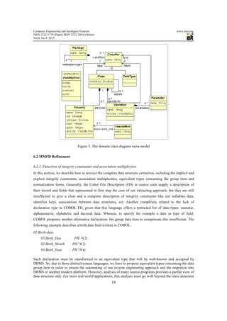
manufacturing. We note that The DCD meta-model shown in figure 5 is a reduced and simplified UML
class diagram [14, 18, 19] that respects the MOF specifications [23]. The meta-class “CLASS” which may
inherit from other classes is composed of properties and operations. A property can be simply an attribute
or an association end that belongs to an association. The operation can contain parameters and it can return
a value. The property, operation’s return and its parameters have a type that can be object class or a
DATATYPE. A property can represent the identifier class; in this case its feature isID must be true.
Concerning the property features lower and upper, they represent the different kind of association
multiplicities.](https://image.slidesharecdn.com/gettingrelationaldatabasefromlegacydata-mdreapproach-130504084924-phpapp01/85/Getting-relational-database-from-legacy-data-mdre-approach-9-320.jpg)
![Computer Engineering and Intelligent Systems www.iiste.org
ISSN 2222-1719 (Paper) ISSN 2222-2863 (Online)
Vol.4, No.4, 2013
20
of the record structures declared in the programs [4]. Therefore, it’s a necessary to include also the analysis
of the legacy data that exist in files in addition to the source code to obtain the entire description of data. In
the second step, based on the structure or the format of the record described in FD and already extracted,
we access to the physical files to parse data and retrieve the necessary constraint, association multiplicities
normal forms and new types to complete our description. To the best of our knowledge all previous work in
literature has done very little research on extracting the constraints and equivalent types from the exiting
data in files. Meanwhile, such physical data contains vital information that can be retrieved implicitly [5].
Our proposal is to use the physical data present in files in order to normalize the resulting database and
complete data description like primary key, not-null constraint, foreign key, association multiplicities
between data structures, equivalent types etc. The following paragraph will further illustrate the principals
rules used to obtain a complete data description:
1) Primary key Rule
Sometimes, the record key is not declared, such as sequential files. In fact, analyzing only source code is
useless to determine the record key and the alternative will be analyzing data existing in files. Assume we
have different occurrences of Record R1 in physical data file. We determine the record key RK or the
primary key by choosing the minimal field(s) where their values are unique and unrepeated. If they are
more than one candidate key we exceed to other criteria: the type and the length of the field(s). It is
judicious to choose from key candidates, an integer primary key and it is shorter (less length) than the other
ones. The following equation (1) shows the above explained:
(1)
2) Unique Rule
Let Fi a record field, to ensure that Fi is unique its values must be unique and they are not repeated in the
different record occurrences.
(2)
3) Not-null Rule
This rule allows determining the fields which are annullable by examining their values in physical files and
ensuring that they are all not null or not empty. So the corresponding equation (3):
(3)
4) Foreign key Rule
Suppose that we have two records R1 et R2 and RK1 is the record key of the Record R1.To find foreign
key in R2, we must consider only fields existing in R2 with the same type as the record key RK1 in R1. If
they are many ones, from those we chose the field(s) that their values exist as values of RK1 in R1. The
following illustrate the equation (4) used to retrieve foreign key from R2.
(4)
5) Bidirectional Association one-to-one/one-to-many Rule
<≠∀
≡
≠∈∧≠∀
∈∃
=
)jlength(F)ilength(Fi,j
integer)itype(F
kVj)/ViValues(FkVjVk,j
R1ii/F
RKR1
≠∈∧≠∀
∈∃
=
kVjV/)iF(ValueskVjV,kj
1RiF/i
RK1R
φ≠∈∀
∈
=
i/V)iF(ValuesiVi,
R1F
null-notF
∈⇒∈∀
≡
∈∃
=
=
)1RK(ValuesVj)F(ValuesV,j
)1RK(type)F(type
2RF/i
1R1RKSoit
2R
ij
i
i
RK
FK](https://image.slidesharecdn.com/gettingrelationaldatabasefromlegacydata-mdreapproach-130504084924-phpapp01/85/Getting-relational-database-from-legacy-data-mdre-approach-11-320.jpg)

![Computer Engineering and Intelligent Systems www.iiste.org
ISSN 2222-1719 (Paper) ISSN 2222-2863 (Online)
Vol.4, No.4, 2013
22
(9)
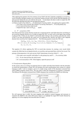
6.2.2. Normalization Rules
The essential goal of normalization is to avoid transactional anomalies that can result from poor data
modeling and avoid a number of probable problems such as reading anomalies, writing anomalies, data
redundancy and non performance. normalization of data models allows verifying the robustness of their
design to improve the modeling and to optimize data storage by applying the normal forms. Normal forms
are nested, so the respect of the normal form of higher level implies respect for the normal forms of lower
levels.
1) 1st
normal form (1NF)
In Cobol programs, multivalued fields are generally declared as arrays like a customer record that can have
tree adresses at same time:
01 Customer
02 REF PIC 9(4).
02 Name PIC X(25).
02 Adress PIC X(50) OCCURS 3.
In this case normalization in 1NF consists of avoiding the multivalued fields by transforming the array data
item to a new record associated with the first record. Note that relationship multiplicity should be
one-to-many in side of the record that contains the array and one-to-one in the other side. Otherwise, the
array data item in customer record will be remplaced by an adress reference field (foreign key).
2) 2nd
normal form (2NF)
The second normal form preconizes that the first one is respected and for each field which does not belong
to the record key depends not only on a part of the key but it must depend completely on the key. So, If the
record key is elementary the problem is not raised and the record data structure respect automatically the
second normal form. On other hand, if the record key is composed from many fields, we must verify in the
legacy data existing in physical files, if the values of the different key components are same and identicals
when the values of any other field does not belongs to it are identicals also. Otherwise, the field depends
only from a part of key that don’t change its values. The following equation (10) resume the 2NF rule :
(10)
=∧=⇒≠∧≠∀
=∧=⇒=∧≠∀
∈
=
∑
∑
=
=
n
i
iji
n
i
iiji
n
SsizeGsizePICXGtypeStypeStypejiji
SsizeGsizeStypeGtypeStypeStypejiji
RSSSGSoit
Gtype
1
1
)()()()()(/,
)()()()()()(/,
),...,2,1(
)(
[ ]n,1k)F(V)F(VVV
)F(ValuesV,V;ji;j,i/RFRF,F
)R(Values))F(V),...,F(V),F(V(V)F,..,F,F(RSoit
FN2
kjkiji
jiRK
RKn21RKn21RK
∈∀=⇒=
∈≠∀∉∧∈∀
∈=∧=
=](https://image.slidesharecdn.com/gettingrelationaldatabasefromlegacydata-mdreapproach-130504084924-phpapp01/85/Getting-relational-database-from-legacy-data-mdre-approach-13-320.jpg)


![Computer Engineering and Intelligent Systems www.iiste.org
ISSN 2222-1719 (Paper) ISSN 2222-2863 (Online)
Vol.4, No.4, 2013
28
discuss two major points: one concerning the characteristics of the CETL tool, and which differs from
previous tools presented above, and one concerning the entire MDRE approach.
Related to the first point about tools, the RM/plusDB [6] does not include the meta-modeling concepts, but
it provides an alternative solution allowing COBOL programs access directly to RDBMS instead of access
data files without making any programs change. In other side, SEELA [24] is a reverse engineering tool
that works with many legacy languages such as Ada, Cobol, C, Pascal, PL/M and FORTRAN and it
supports the maintenance and the documentation of structured programs. Meanwhile, it doesn’t incorporate
the PSM meta-models appropriates to those languages and it doesn’t focus on extracting data description or
integrity and normalization rules. It is more oriented treatement and documentation than description of data.
Cobol Access Plus (CAP) [37] has many common points with our CETL tool since CAP operates on file
descriptors in COBOL source language and it generate a common file the Interface
Table 3. Differences between reverse engineering tools
Tool Parsing
source code
Extract integrity
constraints
Extract
FD
Support
Normalization
Support
meta-modeling
RM/plusDB √ X X X X
SEELA √ X √ X X
Cobol √ √ √ √ X
Eclipse √ X X X √
CETL √ √ √ √ √
Dictionary database (DID) to generate database. But for each new changes according the resulting database
obtained by means CAP, we should provide a modification directly on database or reproduce again the
whole process since CAP doesn’t integrate a database model. Finally, Eclipse MoDisco [25] provides an
extensible framework to elaborate a model-driven tool supporting software reverse engineering and
language modernization. And especialy for COBOL, it proposes a COBOL meta-model which
unfortunately does not include the description of data related to the File descriptors presents in programs.
Indeed, the most previous toolsets do not include the MDE concepts and they do not extract generally the
integrity constraints or normalize database by parsing legacy data. Regarding our CETL toolset, it extracts
the different components of COBOL programs and especially the description of file data, to generate a XMI
model conforming to the Cobol meta-model. it can parse also the data stored in physical files of different
organizations: (sequential, indexed line sequential) in order to deduce the integrity constraints and verify
the normalization forms. The CETL tool can be improved to produce the model transformation between
models without need to include the ATL language and ensure totally the automatic process of our proposal.
Table 2 sumurize the main caracteristics and differences between CETL and the selected tools.
The second point of our discussion concerns the evaluation of our MDRE approach, that presents an
automatic process to generate relational database from legacy data extracted from Cobol programs by
transforming the related PSM into the DCD PIM which can open others perspectives to generate further the
relational database, the business objects and the data access objects in order to extend our proposal to
obtain a partial or a total migration into modern platforms such as JEE7 or .NET. While, the proposal works
on COBOL programs that are conform to the norm ANSI 85, the others norms do not affect significantly
our transformation or generally our MDRE approach. Finally, with regard to extract the integrity
constraints and the normalization forms from legacy data, the following considerations must be taken into
account to succeed the proposal:
It is appropriate in our approach to make a choice of programs that work on persistent data files
and it’s not recommend to include programs maneuvering files, sorting, intermediate calculations,
reporting etc.
When the files contain consistent recordsets and more the data volume is greather, there will be
more pertinent results according to extracting of data integrity constraints and normalization
forms.](https://image.slidesharecdn.com/gettingrelationaldatabasefromlegacydata-mdreapproach-130504084924-phpapp01/85/Getting-relational-database-from-legacy-data-mdre-approach-19-320.jpg)
![Computer Engineering and Intelligent Systems www.iiste.org
ISSN 2222-1719 (Paper) ISSN 2222-2863 (Online)
Vol.4, No.4, 2013
29
9. Conclusion and perspectives
Nowadays, many companies still use legacy systems to manage their business, but unfortunately some of
those systems represent a serious problem since they employ non-integrated, inconsistent, and non
normalized data without documentation and modeling supports. Hence, their maintenance and scalability
become too expensive and practically very complex. Our approach proposes a solution that helps them to
be able to control and reduce the cost of legacy system’s maintenance and evolving. The proposal allows
also these companies to be ready for a possible migration of their legacy data to integrated and normalized
relational databases. In this paper, we presented a reverse engineering process based on model-driven
approach to perform this migration.
Before introducing the model-driven reverse engineering an overview of the related works is given
especially those that were interested in reverse engineering. Next, we have presented the main goal of this
proposal that consists firstly on the parsing COBOL source code in order to extract the data structure in a
design PSM that is conform to the COBOL meta-model. Secondly, the different extracted PSM models are
merged in a common model entitled the MMFD necessary to produce a reverse model transformation to
obtain the analysis PIM DCD, which is refined in next phase by adding the integrity constraints and normal
forms, getting out from the physical files corresponding to the programs already parsed. Finally, the refine
DCD will be mapped to the RDM and a DLL SQL script is generated to create a normalized and integrate
relational database.
Our approach falls into the topic which is specialized in applying MDA to automate reverse engineering
process and presents many advantages to practitioners and researchers from industry and academia with a
vested interest in this area to discern the advantages of using MDA approach in reverse engineering
processes. Thus, the different contributions of our work are migrating legacy systems to new scalable ones
that are independents of platforms and protected from any technology rupture, improvement of system
maintenance is an additional proposal’s contribution since the modern platform and languages are much
less expensive to maintain than legacy system. And finally the proposal reduces time re-engineering given
that MDE is a generative approach. In regards to perform our MDRE process the CASE toolset CETL is
developed to extract the both information: structure and rules necessary to obtain the expected result.
This work is a part of other ones that falls into our area of research about reengineering legacy systems that
aims recovering knowledge hidden in those old systems by means of automated reverse engineering
processes and modernize them through automated forward engineering processes [38, 39, 40, 41, 42, 43].
To conclude, modernization of the entire legacy systems by applying reverse engineering process based on
MDE is a vast area of research and it’s still the principal goal that we intend to attain. Meanwhile, we are
convinced that our work is a step in the right direction which can be enriched in future work by
modernizing other parts of legacy systems such as proposing a solution to evolve legacy reporting or
migrating completely legacy systems to modern platforms such as JEE7 or .NET.
References
[1] Darryl, K. Taft: “Application Development: Modernizing COBOL Apps: 10 Reasons Why It`s
Important”; eweek 2011-01-24.
[2] http://www.microfocus.com/aboutmicrofocus/pressroom/releases/pr20100120709820.asp
[3] Jean-Marie Favre, Jonathan Musset ; « Rétro-ingénierie dirigée par les métamodèles » ; Actes des
2èmes journées IDM06, à Lille
[4] J-L. Hainaut, J-M.Hick, J.Henrard, D.Roland, V.Englebert, Knowledge Transfer in Database Reverse
Engineering A Supporting Case Study, Institut d’Informatique, University of Namur, rue Grandgagnage,
21- B-5000 Namur, IEEE 1997.
[5]M. R.Abbasifard, M. Rahgozar, A. Bayati and Pournemati, “Using Automated Database Reverse
Engineering for Database Integration”, International Journal of Engineering and Applied Sciences 1:4 2005](https://image.slidesharecdn.com/gettingrelationaldatabasefromlegacydata-mdreapproach-130504084924-phpapp01/85/Getting-relational-database-from-legacy-data-mdre-approach-20-320.jpg)
![Computer Engineering and Intelligent Systems www.iiste.org
ISSN 2222-1719 (Paper) ISSN 2222-2863 (Online)
Vol.4, No.4, 2013
30
[6] Spencer Rugaber, Srinivas Doddapaneni, “The Transition of Application Programs From COBOL to a
Fourth Generation Language”, ICSM '93 Proceedings of the Conference on Software Maintenance, IEEE
Computer Society Washington, 1993
[7] Chih-Wei Lu, William C.Chu,Chih-Hung Chang,Yeh-Ching Chung, Xiaodong.Liu and Hongji.Yang
“Reverse Engineering”, Handbook of Software Engineering and Knowledge Engineering, Vol.2, p. 5
[8] Edward Yourdon, Structured Walkthroughs, Yourdon Press, 1989
[9] Jean-Luc Hinaut, Introduction to Database Reverse Engineering. LIBD-Laboratory of Database
Application Engineering Institut d’Informatique- University of Namur; May 2002
[10] Chikofsky, E.J., Cross, J.H.: “Reverse engineering and design recovery: A taxonomy”. IEEE Softw.7
(1) (1990).
[11] Florian Deissenboeck, Daniel Ratiu, “A Unified Meta-Model for Concept-Based Reverse
Engineering”, Proc 3rd International Workshop on Metamodels Schemas Grammars and Ontologies for
Reverse Engineering ATEM’06 Johannes Gutenberg Universitat Mainz (2006)
[12] A Proposal for an MDA Foundation Model (2005-04-01), p. 2
[13] C. Atkinson and T. Kühne: "Model-Driven Development: A Metamodeling Foundation", in: IEEE
Software, September/October 2003 (Vol. 20, No. 5), IEEE, pp. 36-41
[14] Object Management Group, Inc. Unified Modeling Language (UML) 2.1.2 Infrastructure,November
2007. Final Adopted Specification, ptc/03-09-15, p.28
[15] Rahgozar M, Oroumchian F., “An effective strategy for legacy systems evolution”, Journal of software
Maintenance & Evolution. Issue 5, Volume 15, September 2003
[16] Casanova M., Amarel De Sa., “Mapping uninterpreted Schemes into Entity-Relationship diagrams,
two applications to conceptual schema design”. IBM J. Res. & Dev., Vol.28, No1, 1984.
[17] Casanova M., Amarel De Sa., “Designing Entity Relationship Schemas for Conventional Information
Systems. In Proc. Of Entity-Relationship Approach, pp. 265-278, 1983.
[18] Object Management Group, Inc. Unified Modeling Language (UML) 2.1.2 Superstructure,November
2007. Final Adopted Specification.
[19] Rumbaugh, Jacobson, et al. - The Unified Modelling Language Reference Manual - 1999
[20] Howden, W.E.; Pak,S., “Problem Domain, Structural and Logical Abstractions in Reverse
Engineering”, Proceedings of the International Conference on Software Maintenance, IEEE Computer
Society Press, pp.214-224,1992
[21] Nilsson E., G., “The translation of COBOL Data Structure to an Entity-Rel-type Conceptual Schema”.
Proceeding of ERA Conference, IEEE/North-Holland 1985
[22] Edwards H. M., Munro M., “Deriving a Logical Model for a System Using Recast Method”.
Proceedings of the 2nd IEEE WC on Reverse Engineering, Toronto, IEEE Computer Society Press 1995.
[23] Object Management Group, Inc. Meta Object Facility (MOF) 2.0 Core Specification, January2006.
Final Adopted Specification.
[24] Harband, J., “SEELA: Maintenance and Documenting by Reverse Engineering”, Proceedings of the
International Conference on Software Maintenance, IEEE Computer Society Press, p.146.1990](https://image.slidesharecdn.com/gettingrelationaldatabasefromlegacydata-mdreapproach-130504084924-phpapp01/85/Getting-relational-database-from-legacy-data-mdre-approach-21-320.jpg)
![Computer Engineering and Intelligent Systems www.iiste.org
ISSN 2222-1719 (Paper) ISSN 2222-2863 (Online)
Vol.4, No.4, 2013
31
[25] JavaTech Journal #10 focusing on Eclipse Indigo,”Eclipse Modisco”, 06-2011
[26] S. Sendall, W. Kozaczynski, Model transformation–the heart and soul of model-driven software
development, IEEE Software Archive 20 (5) (2003) 42–45.
[27] Freddy Allilaire , Jean Bézivin , Frédéric Jouault , Ivan Kurtev, ATL – Eclipse Support for
Model Transformation (2006) : Proc. of the Eclipse Technology eXchange Workshop (eTX) at ECOOP
[28] ATL - a model transformation technology, http://www.eclipse.org/atl/
[29] F. Jouault, F. Allilaire, J. Bezivin, I. Kurtev, ATL: a model transformation tool, Science of Computer
Programming 72 (1–2) (2008) 31–39.
[30] Hausler, PA.; Pleszkoch, M.G.; Linger, R.C.; Hevner, A.R., “Using Function Abstraction to
Understand Program Behavior”, IEEE Software, 7(1), pp. 55-63, January 1990.
[31] Holtzblatt, L.J.; Pizza, R.L; Reubenstein, H.B; Roberts, S.N; Harris, D.R., “Design Recovery for
Distributed Systems”, IEEE Transactions on Software Engineering, 23(7), pp. 461-472, July 1997.
[32] Rock-Evans, R.1990. Reverse Engineering:Markets, Methods and tools, OVUM report
[33] Object Management Group, Meta Object Facility (MOF) 2.0 Query/View/Transformation
Specification, OMG Adopted Specification ptc/05-11-01, 2005,
[34] Davis K., Arora A., A Methodology for Translating a Conventional File System into an
Entity-Relationship Model. Proceedings of ERA, IEEE/North-Holland 1985.
[35] Sere, K.; Wald’en, M., “Reverse Engineering Distributed Algorithms”, Journal of Software
maintenance: Research and Practice, 8(2), pp. 117-144,1996.
[36] OMG, « Object Constraint Language (OCL) Specification, version 2.0 », 2006. http
://www.omg.org/spec/OCL/2.0/.
[37] http://www.rldt.fr/fr/caplus.htm
[38] Omar EL BEGGAR, Brahim BOUSETTA, Taoufiq GADI, Generating methods signatures from
transition state diagram: A model transformation approach. Information Science and Technology (CIST),
2012 IEEE Colloquium in Fez, 4-9
[39] EL BEGGAR Omar, BOUSETTA Brahim, GADI Taoufiq. Automatic code generation by model
transformation from sequence diagram of system’s internal behavior. International Journal of Computer
and Information Technology (IJCIT). November 2012 Vol. 1, Issue: 2. p129-146.
[40] EL BEGGAR Omar, BOUSETTA Brahim, GADI Taoufiq. Comparative Study between Clustering
and Model Driven Reverse Engineering Approaches. International Journal of Lecture Notes on Software
Engineering (LNSE). 2013. In press
[41] EL BEGGAR Omar, BOUSETTA Brahim, GADI Taoufiq. Comparative Study between Clustering
and Model Driven Reverse Engineering Approaches. The 5th International Conference on Computer
Engineering and Technology (ICCET 2013). Vancouver, Canada, 13 and 14 April 2013.
[42] BOUSETTA Brahim, EL BEGGAR Omar, GADI Taoufiq. Generating operations specification from
domain class diagram using transition state diagram. International Journal of Computer and Information
Technology (IJCIT) January 2013 Volume 2, Issue: 1. p29-36.
[43] BOUSETTA Brahim, EL BEGGAR Omar, GADI Taoufiq. A methodology for CIM modelling and its](https://image.slidesharecdn.com/gettingrelationaldatabasefromlegacydata-mdreapproach-130504084924-phpapp01/85/Getting-relational-database-from-legacy-data-mdre-approach-22-320.jpg)


This document summarizes a research paper that proposes a model-driven reverse engineering (MDRE) approach to extract data from legacy COBOL systems and transform it into a normalized relational database. The approach includes four phases: 1) Extraction of data structure models from COBOL source code, 2) Merging of extracted models, 3) Transformation of the merged model into a domain class diagram and refinement by adding integrity constraints and normal forms, 4) Generation of a relational database schema from the domain class diagram. A CASE tool called CETL is developed to support the extraction and merging phases. The paper argues that this MDRE approach provides benefits over traditional reverse engineering like improved abstraction, inclusion of data integrity rules,