Recommended
PPTX
GD&T_Presentation_with_Diagrams with all inage.pptx
PPTX
Styled_GDT_Presentation_with_Images (1).pptx
PPTX
Geometric dimensioning and tolerancing.pptx
PPTX
Geometrical Dimensioning & Tolerancing, GD&T Course. Day1
PPTX
GD&T for Omega Fabrication, Melaka.4-5th March 2017
PPTX
Geometrical Dimensioning & Tolerancing Course for Silitech.Penang
PPTX
Two days GD&T Course for Virtue Technology Sdn Bhd.Day1
PPTX
Geometrical Dimensioning & Tolerancing, GD&T at Improvage Precision,Melaka 22...
PDF
PDF
Fundamentals of GD&T-1.pdf
PPTX
Two days GD&T Course for Virtue Technology Sdn Bhd.Day2
DOCX
Report on Geometric Dimensional Tolerances
PPTX
Geometrical Dimensioning & Tolerancing Course day2 for Silitech.Penang
PPTX
GD&T day 2 Training for Omega Fabrication, Melaka
PPT
Basic Geometrical Dimensioning & Tolerancing Tranning
PPTX
Geometric Dimensioning and Tolerancing
PPTX
Geometric Dimensioning And Tolerancing.pptx
PPTX
Geometric Dimensioning And Tolerancing.pptx
PDF
GDT in mechanical syatem measurement.pdf
PPTX
g d and t powerpoint presenttion at zeal college
PPT
Training program in �Geometric Dimensioning and Tolerancing
PPT
UMA GD&T Be able to explain the main benefits of G D & T 2. Develop a Soli...
PPT
Introduction to Geometric Dimensioning and Tolerancing (GD&T)
PPTX
Geometric dimensioning and tolerancing (GD&T)
PPT
Fundamentals of gd&t
PPTX
Lecture notes of Geometric Dim GD&T.pptx
PPT
PPT
basic GD&Tßsssssssdddsisjejrnrjejejjejejd.ppt
PDF
Understanding Pink in Colour Psychology!
PPTX
mẫu tin học gốc Nguyễn Việt Nam Anh lớp 8G
More Related Content
PPTX
GD&T_Presentation_with_Diagrams with all inage.pptx
PPTX
Styled_GDT_Presentation_with_Images (1).pptx
PPTX
Geometric dimensioning and tolerancing.pptx
PPTX
Geometrical Dimensioning & Tolerancing, GD&T Course. Day1
PPTX
GD&T for Omega Fabrication, Melaka.4-5th March 2017
PPTX
Geometrical Dimensioning & Tolerancing Course for Silitech.Penang
PPTX
Two days GD&T Course for Virtue Technology Sdn Bhd.Day1
PPTX
Geometrical Dimensioning & Tolerancing, GD&T at Improvage Precision,Melaka 22...
Similar to Introduction_to_GD&T_Complete.pptx_growww
PDF
PDF
Fundamentals of GD&T-1.pdf
PPTX
Two days GD&T Course for Virtue Technology Sdn Bhd.Day2
DOCX
Report on Geometric Dimensional Tolerances
PPTX
Geometrical Dimensioning & Tolerancing Course day2 for Silitech.Penang
PPTX
GD&T day 2 Training for Omega Fabrication, Melaka
PPT
Basic Geometrical Dimensioning & Tolerancing Tranning
PPTX
Geometric Dimensioning and Tolerancing
PPTX
Geometric Dimensioning And Tolerancing.pptx
PPTX
Geometric Dimensioning And Tolerancing.pptx
PDF
GDT in mechanical syatem measurement.pdf
PPTX
g d and t powerpoint presenttion at zeal college
PPT
Training program in �Geometric Dimensioning and Tolerancing
PPT
UMA GD&T Be able to explain the main benefits of G D & T 2. Develop a Soli...
PPT
Introduction to Geometric Dimensioning and Tolerancing (GD&T)
PPTX
Geometric dimensioning and tolerancing (GD&T)
PPT
Fundamentals of gd&t
PPTX
Lecture notes of Geometric Dim GD&T.pptx
PPT
PPT
basic GD&Tßsssssssdddsisjejrnrjejejjejejd.ppt
Recently uploaded
PDF
Understanding Pink in Colour Psychology!
PPTX
mẫu tin học gốc Nguyễn Việt Nam Anh lớp 8G
PDF
Architectural Internship Portfolio - Supriya Kirthi
PDF
Why Everything Feels Off Now: A Visual Framework for Reality Drift
PDF
The Website as a Business Hub Moving from a ‘Digital Brochure’ to a Command C...
PDF
The Graph Sunrise Migration User Flow Design Version 2
PPTX
Turn ideas into clear, structured AI flowcharts - AI Flowchart Generator
PDF
Ramalan roshma_Employee_Satisfaction_Engagement_Survey.pdf
PDF
Nina's Architectural Portfolio _ 2026
PPTX
370828545-Original-Performance-With-the-Use-of-the-Media-Autosaved.pdf.pptx
PDF
HarperCollins Publishing Rebrand Process - Understanding the Brand
PPTX
Create clear, well-structured grant proposals with AI - AI Grant Proposal Gen...
PDF
Claire Donnelly Portfolio- Interior design
PPTX
cubichomeinteriors-Interior Designer in Coimbatore
PDF
Nina Bader Architectural Portfolio 2026
PPTX
827456090-Introduction-to-Sadvritta.pptx
PPTX
Elevations-Massing Of the building through forms and colours
PPTX
Permanent Building with Modular Construction .pptx
DOCX
epp subject reviewjhqweqwewkjdhadasdasdqw12312
PDF
Holm Community at St Nicholas Kirk. Full plans
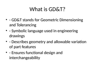
Introduction_to_GD&T_Complete.pptx_growww 1. 2. What is GD&T?
• - GD&T stands for Geometric Dimensioning
and Tolerancing
• - Symbolic language used in engineering
drawings
• - Describes geometry and allowable variation
of part features
• - Ensures functional design and
interchangeability
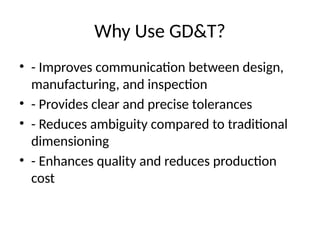
3. Why Use GD&T?
• - Improves communication between design,
manufacturing, and inspection
• - Provides clear and precise tolerances
• - Reduces ambiguity compared to traditional
dimensioning
• - Enhances quality and reduces production
cost
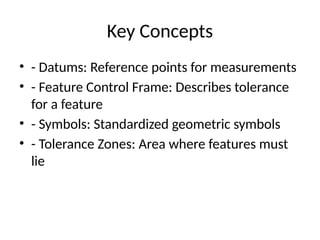
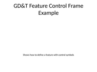
4. Key Concepts
• - Datums: Reference points for measurements
• - Feature Control Frame: Describes tolerance
for a feature
• - Symbols: Standardized geometric symbols
• - Tolerance Zones: Area where features must
lie
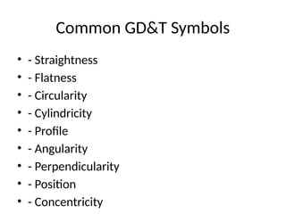
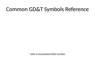
5. Common GD&T Symbols
• - Straightness
• - Flatness
• - Circularity
• - Cylindricity
• - Profile
• - Angularity
• - Perpendicularity
• - Position
• - Concentricity
6. Applications of GD&T
• - Automotive industry
• - Aerospace components
• - Precision machining
• - Mechanical assemblies
7. Conclusion
• - GD&T provides a universal language for
design and manufacturing
• - Enhances precision, quality, and consistency
• - Essential for modern engineering practices
8. 9. 10. 11.
![Introduction to Geometric
Dimensioning and Tolerancing
(GD&T)
• A Modern Approach to Engineering Drawings
• Presented by: [Your Name]
• Date: [Insert Date]](https://image.slidesharecdn.com/introductiontogdtcomplete-250623092136-cac3e983/85/Introduction_to_GD-T_Complete-pptx_growww-1-320.jpg)
![Introduction to Geometric
Dimensioning and Tolerancing
(GD&T)
• A Modern Approach to Engineering Drawings
• Presented by: [Your Name]
• Date: [Insert Date]](https://image.slidesharecdn.com/introductiontogdtcomplete-250623092136-cac3e983/75/Introduction_to_GD-T_Complete-pptx_growww-1-2048.jpg)