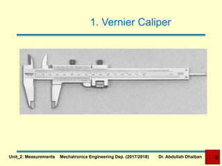
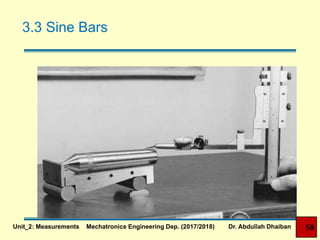
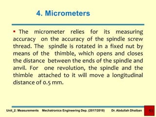
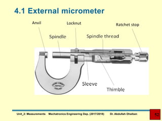
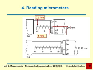
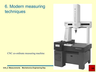
Unit 2: Measurements
Dr. Abdullah Dhaiban
Unit_2: Measurements Mechatronics Engineering Dep. (2017/2018) Dr. Abdullah Dhaiban
Introduction
 Measurement is the comparison of an unknown
dimension to a known standard.
 Good measuring instruments are a key to high volume
production. Without them, parts could not be built
accurately enough to be interchangeable. Each
assembly had to be hand fitted together.
 Today, measuring tools are essential for most machining
operations from initial part layout to final inspection.
Unit_2: Measurements Mechatronics Engineering Dep. (2017/2018) Dr. Abdullah Dhaiban 2
Classification of Measuring
Instruments
 Direct measuring Instruments
 Determine the actual dimension and size of a work
piece
 Indirect measuring Instruments (comparison
instruments)
 Transfer the measurement from the work piece to
the direct measuring instrument, then comparison
is made.
Unit_2: Measurements Mechatronics Engineering Dep. (2017/2018) Dr. Abdullah Dhaiban 3
Engineering Measurements
 Engineering Measurements Include the following
1. Lengths
2. Angles
3. Coordinates (Location)
4. Surfaces
5. Roughness
6. Volumes
7. Force, weight, ….etc.
Unit_2: Measurements Mechatronics Engineering Dep. (2017/2018) Dr. Abdullah Dhaiban 4
Principal Measuring Instruments
 Linear Measurements
 Steel rule
 Calipers
 Vernier caliper
 Micrometers
 Angular Measurements
 Protractors
 Bevel protractor
 Sine bar
5Unit_2: Measurements Mechatronics Engineering Dep. (2017/2018) Dr. Abdullah Dhaiban
Principal Measuring Instruments
 Surface Measurement
 Straight edge
 Surface plate
 Surface gauge
 Optical gauge
 Profilometer
6Unit_2: Measurements Mechatronics Engineering Dep. (2017/2018) Dr. Abdullah Dhaiban
1. Vernier Caliper
 The vernier is a convenient tool to use when
measuring the length of an object, the outer diameter
(OD) of a round or cylindrical object, the inner
diameter (ID) of a pipe, and the depth of a hole
 A vernier caliper (or vernier) is a common tool used in
laboratories and industries to accurately determine
the fraction part of the least count division.
 .
Unit_2: Measurements Mechatronics Engineering Dep. (2017/2018) Dr. Abdullah Dhaiban 7
Unit_2: Measurements Mechatronics Engineering Dep. (2017/2018) Dr. Abdullah Dhaiban 8
1. Vernier Caliper
1. Vernier Caliper
 A vernier consist of two scales: one moving and one
fixed.
 The fixed scale is graduated in millimetres, every 10
divisions equalling 10 mm, and is numbered 0, 1, 2,
3, 4 up to the capacity of the instrument.
 The moving or vernier scale is divided into 50 equal
parts which occupy the same length as 49 divisions
or 49 mm on the fixed scale
9Unit_2: Measurements Mechatronics Engineering Dep. (2017/2018) Dr. Abdullah Dhaiban
85
Fixed
scales Vernier
scales
Locking
screws
A B
C
Beam
Fixed
jaw
Sliding jaw
Adjusting
nut
Vernier caliper adjustment
10Unit_2: Measurements Mechatronics Engineering Dep. (2017/2018) Dr. Abdullah Dhaiban
Vernier scale readings
 This means that the distance
between each graduation on the vernier
scale is 49⁄50 mm= 0.98 mm, or 0.02 mm
less than each division on the fixed
scale (see(a)).
 If the two scales initially have their
zeros in line and the vernier scale is
then moved so that its first graduation
is lined up with a graduation on the
fixed scale, the zero on the vernier scale
will have moved 0.02 mm ((b)).
Vernier scale reading
Unit_2: Measurements Mechatronics Engineering Dep. (2017/2018) Dr. Abdullah Dhaiban 12
Unit_2: Measurements Mechatronics Engineering Dep. (2017/2018) Dr. Abdullah Dhaiban 13
If the second graduation is lined up, the
zero on the vernier scale will have moved
0.04 mm ((c)) and so on.
If graduation 50 is lined up, the zero will
have moved 50 × 0.02 = 1 mm. Since each
division on the vernier scale represents
0.02 mm, five divisions represent 5 × 0.02 =
0.1 mm.
Every fifth division on this scale is marked 1
representing 0.1 mm, 2 representing
0.2 mm and so on Vernier scale readings
Vernier scale readings
Unit_2: Measurements Mechatronics Engineering Dep. (2017/2018) Dr. Abdullah Dhaiban 14
How to read a vernier scale
This reads 3.3
Unit_2: Measurements Mechatronics Engineering Dep. (2017/2018) Dr. Abdullah Dhaiban 15
In the readingThe eleventh line coincides with a line on the fixed scale, therefore
11 × 0.02 = 0.22 mm is added to the reading on the fixed scale, giving a total
reading of 40.22 mm shown in Fig. (a) the vernier scale has moved 40 mm to the
right..
Similarly, in Fig. (b) the vernier scale has moved 120 mm to the right plus 3 mm
and the sixth line coincides, therefore, 6 × 0.02 = 0.12 mm is added to 123 mm,
giving a total of 123.12 mm.
16Unit_2: Measurements Mechatronics Engineering Dep. (2017/2018) Dr. Abdullah Dhaiban
Fixed
scales Vernier
scales
Locking
screws
A B
C
Beam
Fixed
jaw
Sliding
jaw
Adjusting
nut
To take a measurement, loosen both locking screws A and B in the (Fig.).
Move the sliding jaw along the beam until it contacts the surface of the
work being measured. Tighten locking screw B.
Adjust the nut C until the correct ‘feel’ is obtained, then tighten locking
screw A. Re-check ‘feel ’ to ensure that nothing has moved. When you are
satisfied, take the reading on the instrument. Jaws may be carbide tipped
for greater wear resistance
17Unit_2: Measurements Mechatronics Engineering Dep. (2017/2018) Dr. Abdullah Dhaiban
85
External Internal Depth
18Unit_2: Measurements Mechatronics Engineering Dep. (2017/2018) Dr. Abdullah Dhaiban
External, internal and depth measurement
Dial calipers
Are a form of vernier caliper
where readings of 1 mm steps are
taken from the vernier beam and
subdivisions of this are read direct
on a dial graduated in 0.02 mm
divisions.
Figure Dial caliper
19Unit_2: Measurements Mechatronics Engineering Dep. (2017/2018) Dr. Abdullah Dhaiban
Digital caliper
20Unit_2: Measurements Mechatronics Engineering Dep. (2017/2018) Dr. Abdullah Dhaiban
Caliper special jaws
a) Point jaw type – for uneven surface measurement.
b) Offset jaw type – for stepped feature measurement.
(a) uneven surface
(b) stepped feature
21Unit_2: Measurements Mechatronics Engineering Dep. (2017/2018) Dr. Abdullah Dhaiban
Caliper special jaws
c) Neck type – for outside
diameter measurement such
as behind a shrouded recess.
d) Tube thickness type – for
tube or pipewall thickness
measurement
(c) shoulder recess
(d) tube thickness
22Unit_2: Measurements Mechatronics Engineering Dep. (2017/2018) Dr. Abdullah Dhaiban
How to use vernier calliper ?
1. Before use, clean the jaws of the measuring surfaces.
Ensure the instrument reads zero before taking a
measurement.
2. Wipe (clean) sliding surfaces before use.
3. Look straight at the vernier graduations when making
a reading. If viewed from an angle, an error of reading
can be made due to parallax effect
23Unit_2: Measurements Mechatronics Engineering Dep. (2017/2018) Dr. Abdullah Dhaiban
How to use vernier calliper ?
4. Ensure the surface to be measured is clean
5. Do not use excessive force when taking a
measurement.
6. Do not measure a workpiece at a position near the
outer end of the jaws. Move the workpiece as close to
the beam as possible to ensure greatest accuracy of
measurement
7. Keep jaws square/parallel with surface being measure
ensure greatest accuracy.
24Unit_2: Measurements Mechatronics Engineering Dep. (2017/2018) Dr. Abdullah Dhaiban
How to use vernier calliper ?
8. For internal measurement, ensure the inside jaws are
inserted as deeply as possible before taking a
measurement.
9. Be careful not to drop or bang the caliper such as
would cause damage to the instrument.
10. Caliper jaws are very sharp so handle with care to
avoid personal injury.
11. Always store the instrument in a clean place
12. Do not leave the caliper jaws clamped together when
not in use. Always leave a gap between the
measuring faces.
25Unit_2: Measurements Mechatronics Engineering Dep. (2017/2018) Dr. Abdullah Dhaiban
Vernier height gauge
 The beam, carrying the fixed scale, is
attached to a heavy base. The vernier
scale carries a jaw upon which
various attachments can be clamped.
It is most widely used with a chisel-
pointed scribing blade for accurate
marking out, as well as for checking
the height of steps in components.
Vernier height guage
26Unit_2: Measurements Mechatronics Engineering Dep. (2017/2018) Dr. Abdullah Dhaiban
87
Digital height gauge
Vernier depth gauge
27Unit_2: Measurements Mechatronics Engineering Dep. (2017/2018) Dr. Abdullah Dhaiban
2. Calipers
 A caliper is used to transfer and compare a dimension
from one object to another.
 Spring-loaded calipers do not have calibrations. You
obtain measurement by placing the measuring arms
against a rule (stainless steel ruler with English and
Metric scales shown). As you can see the accuracy of
this tool and method does not compare with the
accuracy of the Vernier or electronic caliper.
28Unit_2: Measurements Mechatronics Engineering Dep. (2017/2018) Dr. Abdullah Dhaiban
2.1 Outside caliper
Unit_2: Measurements Mechatronics Engineering Dep. (2017/2018) Dr. Abdullah Dhaiban 29
2.1 Outside caliper
 Spring-loaded OD Calipers are an inexpensive
alternative to vernier calipers.
 They do have limitations - primarily in accuracy and
versatility.
 Advantages other than cost may be in the increased
measuring capacity or range, and heat tolerance
when making rough measurement. Horizontal
threaded rod contains a thumbwheel for adjusting the
width of the two measuring arms.
Unit_2: Measurements Mechatronics Engineering Dep. (2017/2018) Dr. Abdullah Dhaiban 30
2.1 Outside caliper
31Unit_2: Measurements Mechatronics Engineering Dep. (2017/2018) Dr. Abdullah Dhaiban
2.2 Inside Caliper
 Spring-loaded ID Calipers have the same features
and limitations of the OD Calipers. The difference is in
the shape/orientation of the measuring arms allowing
access to the inside of the object.
32Unit_2: Measurements Mechatronics Engineering Dep. (2017/2018) Dr. Abdullah Dhaiban
2.2 Inside Caliper
33Unit_2: Measurements Mechatronics Engineering Dep. (2017/2018) Dr. Abdullah Dhaiban
3. Angular Measurement
 Circles are divided into 360 equal parts, each being a
degree.
 Each of these degrees can be evenly divided into 60
equal parts. These parts are called minutes.
 These minutes can be evenly divided into 60 equal
parts. These parts are called minutes.
34Unit_2: Measurements Mechatronics Engineering Dep. (2017/2018) Dr. Abdullah Dhaiban
3. Angular Measurement
 1 Circle = 360 Degrees ( 360° )
 1 Degree ( 1° ) = 1/360th of a Circle
 1 Degree ( 1°) = 60 Minutes ( 60' )
 1 Minute ( 1' ) = 1/60th of a Degree
 1 Minute ( 1') = 60 Seconds ( 60" )
 1 Second ( 1" ) = 1/60th of a Minute
35Unit_2: Measurements Mechatronics Engineering Dep. (2017/2018) Dr. Abdullah Dhaiban
3. Angular Measurement
 The unit of degree can also be divided into either
decimal or fractional parts and is referred to as decimal
degrees or fractional degrees respectively.
 1½ Degree = 1.5 Degree ( 1.5°)
 87¼ Degrees = 87.25 Degrees ( 87.25° )
36Unit_2: Measurements Mechatronics Engineering Dep. (2017/2018) Dr. Abdullah Dhaiban
3. Angular Measurement
 Minutes and seconds can each be expressed as
decimal or fractional degrees.
 1 Minute ( 1' ) = 1/60th of a Degree = 0.01667°
 1 Second ( 1" ) = 1/60th of a Minute = 0.01667'
37Unit_2: Measurements Mechatronics Engineering Dep. (2017/2018) Dr. Abdullah Dhaiban
3. Angular Measurement
 Change 5°25' to decimal degrees
 Divide the minutes by 60
 Add 0.4167 to 5 = 5.4167°
 5°25' = 5.4167°
 25 divided by 60 = 0.4167
Unit_2: Measurements Mechatronics Engineering Dep. (2017/2018) Dr. Abdullah Dhaiban 38
Angular Measure
Tools
39Unit_2: Measurements Mechatronics Engineering Dep. (2017/2018) Dr. Abdullah Dhaiban
3. Angular Measurement
 Most common tools
1. Simple Protractor
2. Vernier bevel protractor
3. Sine bar
Unit_2: Measurements Mechatronics Engineering Dep. (2017/2018) Dr. Abdullah Dhaiban 40
3.1 Simple Protractor
41Unit_2: Measurements Mechatronics Engineering Dep. (2017/2018) Dr. Abdullah Dhaiban
3.1 Simple Protractor
Whole degree increments
42Unit_2: Measurements Mechatronics Engineering Dep. (2017/2018) Dr. Abdullah Dhaiban
3.2 Vernier bevel protractor
 As well as linear measurement, vernier scales can
equally well be used to determine angular
measurement.
 The vernier bevel protractor uses the principle of two
scales, one moving and one fixed.
Unit_2: Measurements Mechatronics Engineering Dep. (2017/2018) Dr. Abdullah Dhaiban 43
3.2 Vernier bevel protractor
 Used to measure obtuse angle (90º-180º)
 Acute-angle attachment
Fastened to protractor to measure
angles less than 90º
 Main scale divided into
two arcs of 180º
 Scale divided into 12
spaces on each side of 0
 If zero on vernier scale
coincides with line on
main: reading in degrees
Unit_2: Measurements Mechatronics Engineering Dep. (2017/2018) Dr. Abdullah Dhaiban 44
Unit_2: Measurements Mechatronics Engineering Dep. (2017/2018) Dr. Abdullah Dhaiban 45
How to Read a Vernier Protractor?
 Note number of whole degrees between zero on main
scale and zero on vernier scale
 Proceeding in same direction, note which vernier line
coincides with main scale line
 Multiply number by 5' and add to degrees on protractor
dial
 50º
 4 x 5'= 20'
 Reading = 50º 20'
Fourth
46Unit_2: Measurements Mechatronics Engineering Dep. (2017/2018) Dr. Abdullah Dhaiban
3.3 Sine Bars
 Used when accuracy of angle must be checked to
less than 5 minutes
 Consists of steel bar with two cylinders of equal
diameter fastened near ends
 Centers of cylinders exactly 90º to edge
 Distance between centers usually 5 or 10 inches
and 100 or 200 millimeters.
 Made of stabilized tool hardened steel
Unit_2: Measurements Mechatronics Engineering Dep. (2017/2018) Dr. Abdullah Dhaiban 47
3.3 Sine Bars
Unit_2: Measurements Mechatronics Engineering Dep. (2017/2018) Dr. Abdullah Dhaiban 48
3.3 Sine Bars
 Used on surface plates and any
angle by raising one end of bar
with gage blocks
 Made 5 inch or in multiples of 5 or
100 millimeters or multiple of 100
 Distance between lapped
cylinders.
 Face accurate to within .00005 in.
in 5 inches or 0.001 mm in 100
mm.
Unit_2: Measurements Mechatronics Engineering Dep. (2017/2018) Dr. Abdullah Dhaiban 49
3.3 Sine Bars
Unit_2: Measurements Mechatronics Engineering Dep. (2017/2018) Dr. Abdullah Dhaiban 50
4. Micrometers
 The micrometer relies for its measuring
accuracy on the accuracy of the spindle screw
thread. The spindle is rotated in a fixed nut by
means of the thimble, which opens and closes
the distance between the ends of the spindle and
anvil. For one revolution, the spindle and the
thimble attached to it will move a longitudinal
distance of 0.5 mm.
Unit_2: Measurements Mechatronics Engineering Dep. (2017/2018) Dr. Abdullah Dhaiban 51
Anvil Locknut Ratchet stop
52Unit_2: Measurements Mechatronics Engineering Dep. (2017/2018) Dr. Abdullah Dhaiban
4.1 External micrometer
4. Reading micrometers
1 mm
0.5 mm
Unit_2: Measurements Mechatronics Engineering Dep. (2017/2018) Dr. Abdullah Dhaiban 53
Unit_2: Measurements Mechatronics Engineering Dep. (2017/2018) Dr. Abdullah Dhaiban 54
4.1 External Micrometer
 External micrometers with fixed anvils are available
with capacities ranging from 0–13 mm to 575–600
mm.
 External micrometers with interchangeable anvils
(provide an extended range from two to six times
greater than the fixed-anvil types.
 To ensure accurate setting of the interchangeable
anvils, setting gauges are supplied with each
instrument.
Unit_2: Measurements Mechatronics Engineering Dep. (2017/2018) Dr. Abdullah Dhaiban 55
4.1 External Micrometer
External
micrometer
with
interchangeab
le anvils
Unit_2: Measurements Mechatronics Engineering Dep. (2017/2018) Dr. Abdullah Dhaiban 56
57
Micrometer special anvils
4.2 Internal micrometer
 It is designed for inside measurement and consists of
a micrometer measuring head to which may be added
external rods to cover a wide range of measurements
and a spacing collar to make up for the limited range
of the micrometer head.
 Micrometers of less than 300 mm are supplied with a
handle to reach into deep holes.
 Each extension rod is marked with the respective
capacity of the micrometer when that particular rod is
used.
Unit_2: Measurements Mechatronics Engineering Dep. (2017/2018) Dr. Abdullah Dhaiban 58
4.2 Internal micrometer
Digital inside micrometer 59Unit_2: Measurements Mechatronics Engineering Dep. (2017/2018) Dr. Abdullah Dhaiban
4.3 Depth Micrometer
Depth micrometer
Unit_2: Measurements Mechatronics Engineering Dep. (2017/2018) Dr. Abdullah Dhaiban 60
5. Dial indicators
 Dial indicators magnify small movements of a plunger
or lever and show this magnified movement by means
of a pointer on a graduated dial.
 Dial indicators are used to check the dimensional
accuracy of workpieces in conjunction with other
equipment such as gauge blocks, to check
straightness and alignments of machines and
equipment, to set workpieces in machines to ensure
parallelism and concentricity and for a host of other
uses too numerous to list completely.
Unit_2: Measurements Mechatronics Engineering Dep. (2017/2018) Dr. Abdullah Dhaiban 61
5. Dial indicators
Dial test indicator and standPlunger-type dial indicator
Unit_2: Measurements Mechatronics Engineering Dep. (2017/2018) Dr. Abdullah Dhaiban 62
6. Modern measuring
techniques
 Laser scan micrometer
The laser scan micrometer is a high-precision
laser measuring system that performs non-
contact dimensional measurement using a high-
speed scanning laser beam.
Measure workpieces that are (hot workpieces,
brittle or elastic workpieces, workpieces that
must be kept free from contamination, and soft
workpieces which would be affected by
measuring forces.)
Unit_2: Measurements Mechatronics Engineering Dep. (2017/2018) Dr. Abdullah Dhaiban 63
6. Modern measuring
techniques
 Laser scan micrometer
 Basic principle:
A laser beam is directed across the workpiece. The
part of the beam not obstructed by the workpiece
reaches a receiver which sends a signal for processing
and the dimension is displayed digitally on the
connected display unit.
Data software is available which allows import of
measurement data from one or more display units
to a PC for statistical and quality control purposes.
Unit_2: Measurements Mechatronics Engineering Dep. (2017/2018) Dr. Abdullah Dhaiban 64
6. Modern measuring
techniques
 Laser scan micrometer
Laser scan micrometer
Unit_2: Measurements Mechatronics Engineering Dep. (2017/2018) Dr. Abdullah Dhaiban 65
6. Modern measuring
techniques
CNC co-ordinate measuring machine
66Unit_2: Measurements Mechatronics Engineering Dep.
Questions
1. What are the relation between good measuring
instruments and production?
2. How are the measuring instruments classified?
3. What is the accuracy of vernier caliper?
4. What are the types of Vernier caliper?
5. What is the measuring accuracy of a micrometer
without a vernier scale?
Unit_2: Measurements Mechatronics Engineering Dep. (2017/2018) Dr. Abdullah Dhaiban 67
Questions
6. Describe the basic principle of the vernier scale.
7. What is the difference between the graduations of an
external micrometer and a depth micrometer?
8. State the types of measurement which can be carried
out using a vernier caliper.
9. What is the measuring accuracy of vernier bevel
protractor?
10.What is the basic principle of a laser scan micrometer?
Unit_2: Measurements Mechatronics Engineering Dep. (2017/2018) Dr. Abdullah Dhaiban 68

Measurements tools

  • 1.
    Unit 2: Measurements Dr.Abdullah Dhaiban Unit_2: Measurements Mechatronics Engineering Dep. (2017/2018) Dr. Abdullah Dhaiban
  • 2.
    Introduction  Measurement isthe comparison of an unknown dimension to a known standard.  Good measuring instruments are a key to high volume production. Without them, parts could not be built accurately enough to be interchangeable. Each assembly had to be hand fitted together.  Today, measuring tools are essential for most machining operations from initial part layout to final inspection. Unit_2: Measurements Mechatronics Engineering Dep. (2017/2018) Dr. Abdullah Dhaiban 2
  • 3.
    Classification of Measuring Instruments Direct measuring Instruments  Determine the actual dimension and size of a work piece  Indirect measuring Instruments (comparison instruments)  Transfer the measurement from the work piece to the direct measuring instrument, then comparison is made. Unit_2: Measurements Mechatronics Engineering Dep. (2017/2018) Dr. Abdullah Dhaiban 3
  • 4.
    Engineering Measurements  EngineeringMeasurements Include the following 1. Lengths 2. Angles 3. Coordinates (Location) 4. Surfaces 5. Roughness 6. Volumes 7. Force, weight, ….etc. Unit_2: Measurements Mechatronics Engineering Dep. (2017/2018) Dr. Abdullah Dhaiban 4
  • 5.
    Principal Measuring Instruments Linear Measurements  Steel rule  Calipers  Vernier caliper  Micrometers  Angular Measurements  Protractors  Bevel protractor  Sine bar 5Unit_2: Measurements Mechatronics Engineering Dep. (2017/2018) Dr. Abdullah Dhaiban
  • 6.
    Principal Measuring Instruments Surface Measurement  Straight edge  Surface plate  Surface gauge  Optical gauge  Profilometer 6Unit_2: Measurements Mechatronics Engineering Dep. (2017/2018) Dr. Abdullah Dhaiban
  • 7.
    1. Vernier Caliper The vernier is a convenient tool to use when measuring the length of an object, the outer diameter (OD) of a round or cylindrical object, the inner diameter (ID) of a pipe, and the depth of a hole  A vernier caliper (or vernier) is a common tool used in laboratories and industries to accurately determine the fraction part of the least count division.  . Unit_2: Measurements Mechatronics Engineering Dep. (2017/2018) Dr. Abdullah Dhaiban 7
  • 8.
    Unit_2: Measurements MechatronicsEngineering Dep. (2017/2018) Dr. Abdullah Dhaiban 8 1. Vernier Caliper
  • 9.
    1. Vernier Caliper A vernier consist of two scales: one moving and one fixed.  The fixed scale is graduated in millimetres, every 10 divisions equalling 10 mm, and is numbered 0, 1, 2, 3, 4 up to the capacity of the instrument.  The moving or vernier scale is divided into 50 equal parts which occupy the same length as 49 divisions or 49 mm on the fixed scale 9Unit_2: Measurements Mechatronics Engineering Dep. (2017/2018) Dr. Abdullah Dhaiban
  • 10.
    85 Fixed scales Vernier scales Locking screws A B C Beam Fixed jaw Slidingjaw Adjusting nut Vernier caliper adjustment 10Unit_2: Measurements Mechatronics Engineering Dep. (2017/2018) Dr. Abdullah Dhaiban
  • 11.
    Vernier scale readings This means that the distance between each graduation on the vernier scale is 49⁄50 mm= 0.98 mm, or 0.02 mm less than each division on the fixed scale (see(a)).  If the two scales initially have their zeros in line and the vernier scale is then moved so that its first graduation is lined up with a graduation on the fixed scale, the zero on the vernier scale will have moved 0.02 mm ((b)). Vernier scale reading Unit_2: Measurements Mechatronics Engineering Dep. (2017/2018) Dr. Abdullah Dhaiban 12
  • 12.
    Unit_2: Measurements MechatronicsEngineering Dep. (2017/2018) Dr. Abdullah Dhaiban 13
  • 13.
    If the secondgraduation is lined up, the zero on the vernier scale will have moved 0.04 mm ((c)) and so on. If graduation 50 is lined up, the zero will have moved 50 × 0.02 = 1 mm. Since each division on the vernier scale represents 0.02 mm, five divisions represent 5 × 0.02 = 0.1 mm. Every fifth division on this scale is marked 1 representing 0.1 mm, 2 representing 0.2 mm and so on Vernier scale readings Vernier scale readings Unit_2: Measurements Mechatronics Engineering Dep. (2017/2018) Dr. Abdullah Dhaiban 14
  • 14.
    How to reada vernier scale This reads 3.3 Unit_2: Measurements Mechatronics Engineering Dep. (2017/2018) Dr. Abdullah Dhaiban 15
  • 15.
    In the readingTheeleventh line coincides with a line on the fixed scale, therefore 11 × 0.02 = 0.22 mm is added to the reading on the fixed scale, giving a total reading of 40.22 mm shown in Fig. (a) the vernier scale has moved 40 mm to the right.. Similarly, in Fig. (b) the vernier scale has moved 120 mm to the right plus 3 mm and the sixth line coincides, therefore, 6 × 0.02 = 0.12 mm is added to 123 mm, giving a total of 123.12 mm. 16Unit_2: Measurements Mechatronics Engineering Dep. (2017/2018) Dr. Abdullah Dhaiban
  • 16.
    Fixed scales Vernier scales Locking screws A B C Beam Fixed jaw Sliding jaw Adjusting nut Totake a measurement, loosen both locking screws A and B in the (Fig.). Move the sliding jaw along the beam until it contacts the surface of the work being measured. Tighten locking screw B. Adjust the nut C until the correct ‘feel’ is obtained, then tighten locking screw A. Re-check ‘feel ’ to ensure that nothing has moved. When you are satisfied, take the reading on the instrument. Jaws may be carbide tipped for greater wear resistance 17Unit_2: Measurements Mechatronics Engineering Dep. (2017/2018) Dr. Abdullah Dhaiban
  • 17.
    85 External Internal Depth 18Unit_2:Measurements Mechatronics Engineering Dep. (2017/2018) Dr. Abdullah Dhaiban External, internal and depth measurement
  • 18.
    Dial calipers Are aform of vernier caliper where readings of 1 mm steps are taken from the vernier beam and subdivisions of this are read direct on a dial graduated in 0.02 mm divisions. Figure Dial caliper 19Unit_2: Measurements Mechatronics Engineering Dep. (2017/2018) Dr. Abdullah Dhaiban
  • 19.
    Digital caliper 20Unit_2: MeasurementsMechatronics Engineering Dep. (2017/2018) Dr. Abdullah Dhaiban
  • 20.
    Caliper special jaws a)Point jaw type – for uneven surface measurement. b) Offset jaw type – for stepped feature measurement. (a) uneven surface (b) stepped feature 21Unit_2: Measurements Mechatronics Engineering Dep. (2017/2018) Dr. Abdullah Dhaiban
  • 21.
    Caliper special jaws c)Neck type – for outside diameter measurement such as behind a shrouded recess. d) Tube thickness type – for tube or pipewall thickness measurement (c) shoulder recess (d) tube thickness 22Unit_2: Measurements Mechatronics Engineering Dep. (2017/2018) Dr. Abdullah Dhaiban
  • 22.
    How to usevernier calliper ? 1. Before use, clean the jaws of the measuring surfaces. Ensure the instrument reads zero before taking a measurement. 2. Wipe (clean) sliding surfaces before use. 3. Look straight at the vernier graduations when making a reading. If viewed from an angle, an error of reading can be made due to parallax effect 23Unit_2: Measurements Mechatronics Engineering Dep. (2017/2018) Dr. Abdullah Dhaiban
  • 23.
    How to usevernier calliper ? 4. Ensure the surface to be measured is clean 5. Do not use excessive force when taking a measurement. 6. Do not measure a workpiece at a position near the outer end of the jaws. Move the workpiece as close to the beam as possible to ensure greatest accuracy of measurement 7. Keep jaws square/parallel with surface being measure ensure greatest accuracy. 24Unit_2: Measurements Mechatronics Engineering Dep. (2017/2018) Dr. Abdullah Dhaiban
  • 24.
    How to usevernier calliper ? 8. For internal measurement, ensure the inside jaws are inserted as deeply as possible before taking a measurement. 9. Be careful not to drop or bang the caliper such as would cause damage to the instrument. 10. Caliper jaws are very sharp so handle with care to avoid personal injury. 11. Always store the instrument in a clean place 12. Do not leave the caliper jaws clamped together when not in use. Always leave a gap between the measuring faces. 25Unit_2: Measurements Mechatronics Engineering Dep. (2017/2018) Dr. Abdullah Dhaiban
  • 25.
    Vernier height gauge The beam, carrying the fixed scale, is attached to a heavy base. The vernier scale carries a jaw upon which various attachments can be clamped. It is most widely used with a chisel- pointed scribing blade for accurate marking out, as well as for checking the height of steps in components. Vernier height guage 26Unit_2: Measurements Mechatronics Engineering Dep. (2017/2018) Dr. Abdullah Dhaiban
  • 26.
    87 Digital height gauge Vernierdepth gauge 27Unit_2: Measurements Mechatronics Engineering Dep. (2017/2018) Dr. Abdullah Dhaiban
  • 27.
    2. Calipers  Acaliper is used to transfer and compare a dimension from one object to another.  Spring-loaded calipers do not have calibrations. You obtain measurement by placing the measuring arms against a rule (stainless steel ruler with English and Metric scales shown). As you can see the accuracy of this tool and method does not compare with the accuracy of the Vernier or electronic caliper. 28Unit_2: Measurements Mechatronics Engineering Dep. (2017/2018) Dr. Abdullah Dhaiban
  • 28.
    2.1 Outside caliper Unit_2:Measurements Mechatronics Engineering Dep. (2017/2018) Dr. Abdullah Dhaiban 29
  • 29.
    2.1 Outside caliper Spring-loaded OD Calipers are an inexpensive alternative to vernier calipers.  They do have limitations - primarily in accuracy and versatility.  Advantages other than cost may be in the increased measuring capacity or range, and heat tolerance when making rough measurement. Horizontal threaded rod contains a thumbwheel for adjusting the width of the two measuring arms. Unit_2: Measurements Mechatronics Engineering Dep. (2017/2018) Dr. Abdullah Dhaiban 30
  • 30.
    2.1 Outside caliper 31Unit_2:Measurements Mechatronics Engineering Dep. (2017/2018) Dr. Abdullah Dhaiban
  • 31.
    2.2 Inside Caliper Spring-loaded ID Calipers have the same features and limitations of the OD Calipers. The difference is in the shape/orientation of the measuring arms allowing access to the inside of the object. 32Unit_2: Measurements Mechatronics Engineering Dep. (2017/2018) Dr. Abdullah Dhaiban
  • 32.
    2.2 Inside Caliper 33Unit_2:Measurements Mechatronics Engineering Dep. (2017/2018) Dr. Abdullah Dhaiban
  • 33.
    3. Angular Measurement Circles are divided into 360 equal parts, each being a degree.  Each of these degrees can be evenly divided into 60 equal parts. These parts are called minutes.  These minutes can be evenly divided into 60 equal parts. These parts are called minutes. 34Unit_2: Measurements Mechatronics Engineering Dep. (2017/2018) Dr. Abdullah Dhaiban
  • 34.
    3. Angular Measurement 1 Circle = 360 Degrees ( 360° )  1 Degree ( 1° ) = 1/360th of a Circle  1 Degree ( 1°) = 60 Minutes ( 60' )  1 Minute ( 1' ) = 1/60th of a Degree  1 Minute ( 1') = 60 Seconds ( 60" )  1 Second ( 1" ) = 1/60th of a Minute 35Unit_2: Measurements Mechatronics Engineering Dep. (2017/2018) Dr. Abdullah Dhaiban
  • 35.
    3. Angular Measurement The unit of degree can also be divided into either decimal or fractional parts and is referred to as decimal degrees or fractional degrees respectively.  1½ Degree = 1.5 Degree ( 1.5°)  87¼ Degrees = 87.25 Degrees ( 87.25° ) 36Unit_2: Measurements Mechatronics Engineering Dep. (2017/2018) Dr. Abdullah Dhaiban
  • 36.
    3. Angular Measurement Minutes and seconds can each be expressed as decimal or fractional degrees.  1 Minute ( 1' ) = 1/60th of a Degree = 0.01667°  1 Second ( 1" ) = 1/60th of a Minute = 0.01667' 37Unit_2: Measurements Mechatronics Engineering Dep. (2017/2018) Dr. Abdullah Dhaiban
  • 37.
    3. Angular Measurement Change 5°25' to decimal degrees  Divide the minutes by 60  Add 0.4167 to 5 = 5.4167°  5°25' = 5.4167°  25 divided by 60 = 0.4167 Unit_2: Measurements Mechatronics Engineering Dep. (2017/2018) Dr. Abdullah Dhaiban 38
  • 38.
    Angular Measure Tools 39Unit_2: MeasurementsMechatronics Engineering Dep. (2017/2018) Dr. Abdullah Dhaiban
  • 39.
    3. Angular Measurement Most common tools 1. Simple Protractor 2. Vernier bevel protractor 3. Sine bar Unit_2: Measurements Mechatronics Engineering Dep. (2017/2018) Dr. Abdullah Dhaiban 40
  • 40.
    3.1 Simple Protractor 41Unit_2:Measurements Mechatronics Engineering Dep. (2017/2018) Dr. Abdullah Dhaiban
  • 41.
    3.1 Simple Protractor Wholedegree increments 42Unit_2: Measurements Mechatronics Engineering Dep. (2017/2018) Dr. Abdullah Dhaiban
  • 42.
    3.2 Vernier bevelprotractor  As well as linear measurement, vernier scales can equally well be used to determine angular measurement.  The vernier bevel protractor uses the principle of two scales, one moving and one fixed. Unit_2: Measurements Mechatronics Engineering Dep. (2017/2018) Dr. Abdullah Dhaiban 43
  • 43.
    3.2 Vernier bevelprotractor  Used to measure obtuse angle (90º-180º)  Acute-angle attachment Fastened to protractor to measure angles less than 90º  Main scale divided into two arcs of 180º  Scale divided into 12 spaces on each side of 0  If zero on vernier scale coincides with line on main: reading in degrees Unit_2: Measurements Mechatronics Engineering Dep. (2017/2018) Dr. Abdullah Dhaiban 44
  • 44.
    Unit_2: Measurements MechatronicsEngineering Dep. (2017/2018) Dr. Abdullah Dhaiban 45
  • 45.
    How to Reada Vernier Protractor?  Note number of whole degrees between zero on main scale and zero on vernier scale  Proceeding in same direction, note which vernier line coincides with main scale line  Multiply number by 5' and add to degrees on protractor dial  50º  4 x 5'= 20'  Reading = 50º 20' Fourth 46Unit_2: Measurements Mechatronics Engineering Dep. (2017/2018) Dr. Abdullah Dhaiban
  • 46.
    3.3 Sine Bars Used when accuracy of angle must be checked to less than 5 minutes  Consists of steel bar with two cylinders of equal diameter fastened near ends  Centers of cylinders exactly 90º to edge  Distance between centers usually 5 or 10 inches and 100 or 200 millimeters.  Made of stabilized tool hardened steel Unit_2: Measurements Mechatronics Engineering Dep. (2017/2018) Dr. Abdullah Dhaiban 47
  • 47.
    3.3 Sine Bars Unit_2:Measurements Mechatronics Engineering Dep. (2017/2018) Dr. Abdullah Dhaiban 48
  • 48.
    3.3 Sine Bars Used on surface plates and any angle by raising one end of bar with gage blocks  Made 5 inch or in multiples of 5 or 100 millimeters or multiple of 100  Distance between lapped cylinders.  Face accurate to within .00005 in. in 5 inches or 0.001 mm in 100 mm. Unit_2: Measurements Mechatronics Engineering Dep. (2017/2018) Dr. Abdullah Dhaiban 49
  • 49.
    3.3 Sine Bars Unit_2:Measurements Mechatronics Engineering Dep. (2017/2018) Dr. Abdullah Dhaiban 50
  • 50.
    4. Micrometers  Themicrometer relies for its measuring accuracy on the accuracy of the spindle screw thread. The spindle is rotated in a fixed nut by means of the thimble, which opens and closes the distance between the ends of the spindle and anvil. For one revolution, the spindle and the thimble attached to it will move a longitudinal distance of 0.5 mm. Unit_2: Measurements Mechatronics Engineering Dep. (2017/2018) Dr. Abdullah Dhaiban 51
  • 51.
    Anvil Locknut Ratchetstop 52Unit_2: Measurements Mechatronics Engineering Dep. (2017/2018) Dr. Abdullah Dhaiban 4.1 External micrometer
  • 52.
    4. Reading micrometers 1mm 0.5 mm Unit_2: Measurements Mechatronics Engineering Dep. (2017/2018) Dr. Abdullah Dhaiban 53
  • 53.
    Unit_2: Measurements MechatronicsEngineering Dep. (2017/2018) Dr. Abdullah Dhaiban 54
  • 54.
    4.1 External Micrometer External micrometers with fixed anvils are available with capacities ranging from 0–13 mm to 575–600 mm.  External micrometers with interchangeable anvils (provide an extended range from two to six times greater than the fixed-anvil types.  To ensure accurate setting of the interchangeable anvils, setting gauges are supplied with each instrument. Unit_2: Measurements Mechatronics Engineering Dep. (2017/2018) Dr. Abdullah Dhaiban 55
  • 55.
    4.1 External Micrometer External micrometer with interchangeab leanvils Unit_2: Measurements Mechatronics Engineering Dep. (2017/2018) Dr. Abdullah Dhaiban 56
  • 56.
  • 57.
    4.2 Internal micrometer It is designed for inside measurement and consists of a micrometer measuring head to which may be added external rods to cover a wide range of measurements and a spacing collar to make up for the limited range of the micrometer head.  Micrometers of less than 300 mm are supplied with a handle to reach into deep holes.  Each extension rod is marked with the respective capacity of the micrometer when that particular rod is used. Unit_2: Measurements Mechatronics Engineering Dep. (2017/2018) Dr. Abdullah Dhaiban 58
  • 58.
    4.2 Internal micrometer Digitalinside micrometer 59Unit_2: Measurements Mechatronics Engineering Dep. (2017/2018) Dr. Abdullah Dhaiban
  • 59.
    4.3 Depth Micrometer Depthmicrometer Unit_2: Measurements Mechatronics Engineering Dep. (2017/2018) Dr. Abdullah Dhaiban 60
  • 60.
    5. Dial indicators Dial indicators magnify small movements of a plunger or lever and show this magnified movement by means of a pointer on a graduated dial.  Dial indicators are used to check the dimensional accuracy of workpieces in conjunction with other equipment such as gauge blocks, to check straightness and alignments of machines and equipment, to set workpieces in machines to ensure parallelism and concentricity and for a host of other uses too numerous to list completely. Unit_2: Measurements Mechatronics Engineering Dep. (2017/2018) Dr. Abdullah Dhaiban 61
  • 61.
    5. Dial indicators Dialtest indicator and standPlunger-type dial indicator Unit_2: Measurements Mechatronics Engineering Dep. (2017/2018) Dr. Abdullah Dhaiban 62
  • 62.
    6. Modern measuring techniques Laser scan micrometer The laser scan micrometer is a high-precision laser measuring system that performs non- contact dimensional measurement using a high- speed scanning laser beam. Measure workpieces that are (hot workpieces, brittle or elastic workpieces, workpieces that must be kept free from contamination, and soft workpieces which would be affected by measuring forces.) Unit_2: Measurements Mechatronics Engineering Dep. (2017/2018) Dr. Abdullah Dhaiban 63
  • 63.
    6. Modern measuring techniques Laser scan micrometer  Basic principle: A laser beam is directed across the workpiece. The part of the beam not obstructed by the workpiece reaches a receiver which sends a signal for processing and the dimension is displayed digitally on the connected display unit. Data software is available which allows import of measurement data from one or more display units to a PC for statistical and quality control purposes. Unit_2: Measurements Mechatronics Engineering Dep. (2017/2018) Dr. Abdullah Dhaiban 64
  • 64.
    6. Modern measuring techniques Laser scan micrometer Laser scan micrometer Unit_2: Measurements Mechatronics Engineering Dep. (2017/2018) Dr. Abdullah Dhaiban 65
  • 65.
    6. Modern measuring techniques CNCco-ordinate measuring machine 66Unit_2: Measurements Mechatronics Engineering Dep.
  • 66.
    Questions 1. What arethe relation between good measuring instruments and production? 2. How are the measuring instruments classified? 3. What is the accuracy of vernier caliper? 4. What are the types of Vernier caliper? 5. What is the measuring accuracy of a micrometer without a vernier scale? Unit_2: Measurements Mechatronics Engineering Dep. (2017/2018) Dr. Abdullah Dhaiban 67
  • 67.
    Questions 6. Describe thebasic principle of the vernier scale. 7. What is the difference between the graduations of an external micrometer and a depth micrometer? 8. State the types of measurement which can be carried out using a vernier caliper. 9. What is the measuring accuracy of vernier bevel protractor? 10.What is the basic principle of a laser scan micrometer? Unit_2: Measurements Mechatronics Engineering Dep. (2017/2018) Dr. Abdullah Dhaiban 68