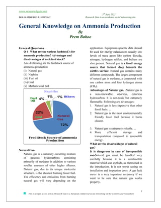
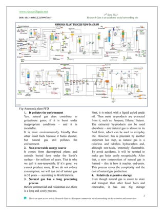
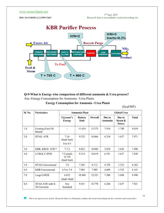
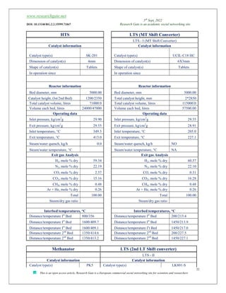
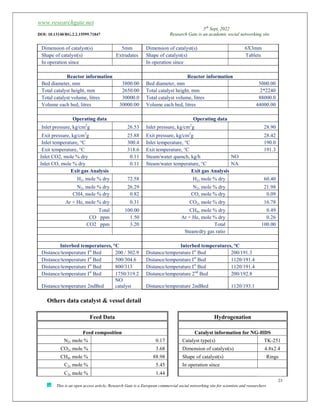
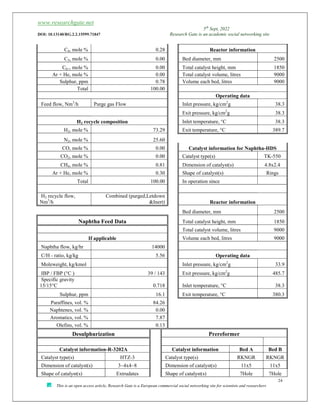
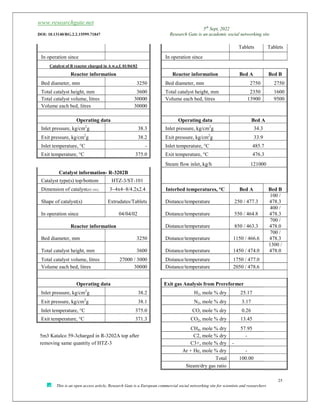
The present paper description of Ammonia Plant, Production of Green Hydrogen, Different types of revamp option of Ammonia & urea plant different types of ammonia process, calculation. This paper is very useful for Engineering students, new comers in fertilizers Industries .Practical data detail of vessel, Electric heating primary reformer and what is the difference of Gas fired primary reformer and Electric heating, calculation, efficiency etc.
General Knowledge on Ammonia Production By Prem Baboo.pdf
1. www.researchgate.net
5th
Sept, 2022
DOI: 10.13140/RG.2.2.15599.71847 Research Gate is an academic social networking site
1
This is an open access article, Research Gate is a European commercial social networking site for scientists and researchers
General Knowledge on Ammonia Production
By
Prem Baboo
General Questions
Q-1- What are the various feedstock’s for
ammonia production? Advantages and
disadvantages of each feed stock?
Ans.-Following are the feedstock source of
ammonia production
(i) Natural gas
(ii) Naphtha
(iii) Fuel oil
(iv) Coal
(v) Methane coal bed
Natural Gas-
Natural gas is a naturally occurring mixture
of gaseous hydrocarbons consisting
primarily of methane in addition to various
smaller amounts of other higher alkenes.
Natural gas, due to its unique molecular
structure, is the cleanest burning fossil fuel.
The efficiency and emissions from burning
natural gas will vary depending on the
application. Equipment-specific data should
be used for energy calculations usually low
levels of trace gases like carbon dioxide,
nitrogen, hydrogen sulfide, and helium are
also present. Natural gas is a fossil energy
source that formed deep beneath the
earth's surface. Natural gas contains many
different compounds. The largest component
of natural gas is methane, a compound with
one carbon atom and four hydrogen atoms
(CH4).
Advantages of Natural gas. -Natural gas is
a non-renewable, odorless, colorless
hydrocarbon. It is non-toxic but extremely
flammable. Following are advantages-
1. Natural gas is less expensive than other
fossil fuels. ...
2. Natural gas is the most environmentally
friendly fossil fuel because it burns
cleaner.
3. Natural gas is extremely reliable. ...
4. More efficient storage and
transportation compared to renewable
energy.
What are the disadvantages of natural
gas?
It is dangerous in case of irresponsible
use-Natural gas must be handled very
carefully because it is a combustible
material which can explode, as mentioned in
the introduction. It is not worth saving on
installation and inspection costs. A gas leak
meter is a very important accessory if we
want to be sure that natural gas works
properly.
2. www.researchgate.net
5th
Sept, 2022
DOI: 10.13140/RG.2.2.15599.71847 Research Gate is an academic social networking site
2
This is an open access article, Research Gate is a European commercial social networking site for scientists and researchers
Fig-Ammonia plant PFD
1. It pollutes the environment
Yes, natural gas does contribute to
greenhouse gases, if it is burnt under
inappropriate conditions – and it is
inevitable.
It is more environmentally friendly than
other fossil fuels because it burns cleaner,
but natural gas still pollutes the
environment.
2. Non-renewable energy source
It comes from decomposed plants and
animals buried deep under the Earth’s
surface – for millions of years. That is why
we call it non-renewable. If it’s gone, we
cannot produce more. If we do not reduce
consumption, we will run out of natural gas
in 52 years — according to World meters.
3. Natural gas has a long processing
process
Before commercial and residential use, there
is a long and costly process.
First, it is mixed with a liquid called crude
oil. Then most by-products are extracted
from it, such as: Propane, Ethane, Butane.
The extracted by-products can be used
elsewhere – and natural gas is almost in its
final form, which can be used in everyday
life. However, this is preceded by another
important last step, as natural gas is a
colorless and odorless hydrocarbon and,
although non-toxic, extremely flammable.
To avoid accidents, it will be scented to
make gas leaks easily recognizable. After
that, a new composition of natural gas is
formed – this is how it reaches end-users.
This process raises the complexity and the
cost of natural gas production.
4. Relatively expensive storage
Even though natural gas is easier to store
and transport than other fossil fuels and
renewable, it has one big storage
3. www.researchgate.net
5th
Sept, 2022
DOI: 10.13140/RG.2.2.15599.71847 Research Gate is an academic social networking site
3
This is an open access article, Research Gate is a European commercial social networking site for scientists and researchers
Disadvantage. Its volume happens to be four
times as big as petrol’s.
Because of this, natural gas storage is much
more expensive since more storage space is
needed.
Q-2-Which is the best feedstock and why.
Ans.-One way of making green ammonia is
by using hydrogen from water electrolysis
and nitrogen separated from the air. These
are then fed into the Haber process (also
known as Haber-Bosch), all powered by
sustainable electricity. But green ammonia is
very costly; it will take time to produce
green ammonia. Apart from this natural gas
is the best source of ammonia production.
Natural gas has the highest energy content
with a value of about 50,000 kJ per
kilogram or 42-46 MJ/m3
, depending on
the quality/source of natural gas. In Calorie
8180-8250 K.Cal/Nm3
. Natural gas mainly
contains methane and smaller amounts of
ethane, propane, butane, and heavier
hydrocarbons along with varying amounts of
water vapors, carbon dioxide, sulfur
compounds, and other non-hydrocarbons.
Ethane, propane, butane, and propane are
known as associated gases.
Limit CH4 C2h6 C3H18 C4H10 CO2 N2 Relative
density
air=1
HHV(MJ/
m3
)
Average 95.52 2.627 0.441 0.136 0.40 0.74 0.580 38.58
Max 98.86 5.135 1.522 0.155 0.64 1.21 0.591 39.21
Min 93.33 0.225 0.028 0.017 0.01 0.43 0.563 37.55
Q-3-What are the main technologies of
ammonia production?
Ans. - Following are main technologies of
ammonia production,
three technology licensors —
1. KBR (Kellogg Brown and Root),
2. Haldor Topsøe, and
3. ThyssenKrupp Industrial Solutions
(TKIS)
4. Casale. (Currently dominate the
market. Ammonia Casale, which offers
an axial-radial catalyst bed design, is a
market leader in revamps of existing
plants.)
Q-4-What is the basis / factors of selecting
a specific technology?
Ans.-For selecting technology following
point should be remember
1. Easy operation
2. The material transportation
3. Energy point of view should be less
4. Cost of the plants/technology
5. Life of the plant
6. Environment point of view.
7. Riles and guidelines of the nations
Q-5- What is the difference between
Steam reforming and partial oxidation.
Which is better and why?
Ans.-partial oxidation takes place in
Gasification process in the presence of
limited oxygen and Gas separation unit is
compulsory for producing oxygen. The term
partial oxidation is a relative term which
simply means that less oxygen is used in
gasification than would be required for
combustion (i.e., burning or complete
oxidation) of the same amount of fuel
.Partial oxidation also produces a producer
gas with a lower H/C ratio
4. www.researchgate.net
5th
Sept, 2022
DOI: 10.13140/RG.2.2.15599.71847 Research Gate is an academic social networking site
4
This is an open access article, Research Gate is a European commercial social networking site for scientists and researchers
While reforming takes place in presence of
steam and air. The reforming process is
better. Compared to steam reforming, higher
pressures and temperatures are typically
required to produce a gas with high
(CO+H2). Historically, partial oxidation has
not been widely used in DR processes, but
new advances in the technology may change
this.
Partial oxidation (POX or POX) reactions
occur when a sub-stoichiometric fuel-air
mixture is partially combusted in a
reformer. The general reaction equation
without catalyst (thermal partial oxidation,
TPOX) is of the form
CnHm+2(n+m)/2O2→nCO+ (m/2) H2O
A possible reaction equation (coal):
CH feedstock + O2→CO+6H2
Gasification Process Sequence and
following sections
1. Air Separation
2. Shell Gasification and Carbon Recovery
3. Rectisol De sulphurisation
4. Shift Conversion
5. Rectisol Decarbonation
6. Nitrogen Wash Unit
7. Ammonia Synthesis, Refrigeration &
Storage
8. Sulphur Recovery by Claus process
A TPOX reactor is similar to the auto
thermal reactor – the main difference being
no catalyst is used. The feedstock, which
may include steam, is mixed directly with
oxygen by an injector which is located near
the top of the reaction vessel. Both partial
oxidation reactions as well as reforming
reactions occur in the combustion zone
below the burner. The principal advantage
of the partial oxidation process is the ability
of the process to accept a wide variety of
feed stocks, which can comprise very high
molecular weight organics, for
example petroleum coke .Additionally, since
emission of NOx and SOx are minimal, the
technology can be considered
environmentally benign.
6. www.researchgate.net
5th
Sept, 2022
DOI: 10.13140/RG.2.2.15599.71847 Research Gate is an academic social networking site
6
This is an open access article, Research Gate is a European commercial social networking site for scientists and researchers
Q-6 –What is the option of old Urea
(Conventional Process) for revamp?
Ans.- The old urea plant designed with
conventional process consumes high energy due
to crystallization route based on Mitsui-Toatsu
Total Recycle C-improved process, Montedition
process and Stamicarbon conventional process.
The urea produce through this process doesn’t
have much acceptability in the market against
other brand. In order to upgrade urea quality and
reduce energy consumption as per market
demand, the following alternative process
technologies can be considered for the revamp:
1. ACES improved Process
2. Urea Casale Process Along with the
improvement based on the above process
technologies, installation of hydrolyzer,
improvement of urea prills quality and
granulated urea has also been considered for
urea plant.
The urea plant reactor may be the same; the
crystallizer may convert with vacuum section.
The reciprocating compressor will be changed
into centrifugal compressor.
The existing urea plant is not able to maintain
the quality of urea compared to other units. This
is because of existing high pressure of urea
reactor and decomposition with flashing. To
obtain quality of urea product and to have an
edge in competitive market scenario,
replacement of existing crystallization section
with vacuum concentration section and new
prilling tower is recommended. Installation of
hydrolyser /stripper system is also recommended
as a pollution abatement measure.
8. www.researchgate.net
5th
Sept, 2022
DOI: 10.13140/RG.2.2.15599.71847 Research Gate is an academic social networking site
8
This is an open access article, Research Gate is a European commercial social networking site for scientists and researchers
Q-7- What is the comparison of different
Ammonia technology for revamping existing
plants?
An.,- Process technology from various process
licensors have been compared and presented in
following Table-
Only modified burners in gasifiers (Lurgi’s G-
Pox) along with modification of rectisol
Decarbonation to produce adequate CO2 for urea
plants.
• Auto thermal reforming (Lurgi’s C-Pox,
HTAS, KBR) along with modification of rectisol
de carbonation by Lurgi and KBR to produce
adequate CO2 for urea plant. HTAS will use
aMDEA process for CO2 recovery.
• New conventional front end (HTAS & KBR)
For additional reduction in specific energy
consumption, Lurgi and Ammonia Casale have
offered revamp option of synthesis section too.
11. www.researchgate.net
5th
Sept, 2022
DOI: 10.13140/RG.2.2.15599.71847 Research Gate is an academic social networking site
11
This is an open access article, Research Gate is a European commercial social networking site for scientists and researchers
Q-8-Advantages of electrically heated
primary reformer and what is the future?
And compare?
Ans.-Electrically heated Steam Natural gas
reforming (e-NGR) combined with Carbon
Capture and Storage (CCS) is a way to produce
clean syngas and/or hydrogen at industrial scale
that can be used to produce chemicals such as
methanol/Ammonia etc.
Large-scale production of hydrogen through
steam reforming directly produces CO2 as a side
product. In addition, the heating of reactors
through fossil-fuel burning contributes further
CO2 emissions. One problem is that the catalyst
bed is heated unevenly, which renders much of
the catalyst effectively inactive. An electrical
heating scheme for a metal tube reactor that
improves the uniformity of heating and catalyst
usage . Adoption of this alternative approach
could affect CO2 emissions by up to
approximately 1% of global emissions.
Chemical reactors have the potential to reduce
CO2 emissions and provide flexible and compact
heat generation. Here, we describe a disruptive
approach to a fundamental process by
integrating an electrically heated catalytic
structure directly into a steam-methane–
reforming (SMR) reactor for hydrogen
production. Intimate contact between the electric
heat source and the reaction site drives the
reaction close to thermal equilibrium, increases
catalyst utilization, and limits unwanted
byproduct formation. The integrated design with
small characteristic length scales allows compact
reactor designs, potentially 100 times smaller
than current reformer platforms. Electrification
of SMR offers a strong platform for new reactor
design, scale, and implementation opportunities.
Implemented on a global scale, this could
correspond to a reduction of nearly 1% of all
CO2 emissions.
12. www.researchgate.net
5th
Sept, 2022
DOI: 10.13140/RG.2.2.15599.71847 Research Gate is an academic social networking site
12
This is an open access article, Research Gate is a European commercial social networking site for scientists and researchers
Fig- Difference of Gas fired and Eclectic heating Reformer.
Compound Data Modeling
HHV LHV HHV LHV
Btu/scf Btu/scf Kcal/g. mole Btu/scf Kcal/g. mole Btu/scf
Hydrogen 324.2 273.8 68.7 325.9 57.5 273.9
Methane 1010 909.4 213.6 1013.1 191.7 909.1
CO 320.5 320.5 67.6 320.6 67.6 320.6
CO2 0.0 0.0 0.0 0.0 0.0 0.0
Coal Bed Methane
Coal Bed Methane: The Coal Bed Methane
is a gas similar to natural gas which contains
more than 90% methane. The CBM gas can
be also utilized as a feed stock for the
Ammonia/ Urea fertilizer complex.
13. www.researchgate.net
5th
Sept, 2022
DOI: 10.13140/RG.2.2.15599.71847 Research Gate is an academic social networking site
13
This is an open access article, Research Gate is a European commercial social networking site for scientists and researchers
However, it is a bit premature to depend on
this source unless more information on
production of CBM from these blocks is
available. The potential CBM blocks are
geographical wide spread spanning from
Rajasthan to AP or in MP. So far in India
sixteen blocks have been awarded through
two rounds of bidding and in 3rd round 10
more blocks has been awarded. The likely
production volumes of CBM – I & CBM-II
blocks is of the tune of 21 MMSCMD and
production is likely to start in 2007-08. The
approximate cost of CBM gas is 5.5 US$ /
MMBTU.
Coal Gasification: With the improved
technology and the equipment available
to handle poor quality of Indian Coal
this has very high ash content of 32-
35%. Today technologies for reducing
the ash content in a cost effective
manner are available. This opens up
opportunities for using the established
coal gasification technologies which has
been successfully used in China. Coal
gasification is a viable option for urea
production with delivered coal prices
being around US$ 2.5 / MMBTU as
against US$ 9 for spot LNG and US$ 14
for naphtha. However, serious effort in
this direction has to be made. India is
endowed with huge reserves of coal and
lignite. Out of the total coal reserves a
large quantity exists at un-mineable
depth. Underground Coal Gasification
(UCG) is a process which burns
coal/Lignite in-situ in the seam in
presence of air/oxygen to produce
gaseous mixture consisting of CO2, CO,
CH4, H2, and N2 etc. The gas in turn
can be used for generation of power,
generation of Liquid Hydrocarbon fuel
or in the production of Ammonia &
Urea.
14. www.researchgate.net
5th
Sept, 2022
DOI: 10.13140/RG.2.2.15599.71847 Research Gate is an academic social networking site
14
This is an open access article, Research Gate is a European commercial social networking site for scientists and researchers
Fig-Gas fired Reformer & Electric heating.
Energy value may have to be discounted when
combining different type
Should the HHV be discounted when combining
with heat values?
Basic stoichiometery –CH4 + 2H2O→CO2 +4H2
15. www.researchgate.net
5th
Sept, 2022
DOI: 10.13140/RG.2.2.15599.71847 Research Gate is an academic social networking site
15
This is an open access article, Research Gate is a European commercial social networking site for scientists and researchers
How do we provide the heat of reaction?
18. www.researchgate.net
5th
Sept, 2022
DOI: 10.13140/RG.2.2.15599.71847 Research Gate is an academic social networking site
18
This is an open access article, Research Gate is a European commercial social networking site for scientists and researchers
Q-9-What is Energy wise comparison of different ammonia & Urea process?
Ans.-Energy Consumption for Ammonia –Urea Plants
19. www.researchgate.net
5th
Sept, 2022
DOI: 10.13140/RG.2.2.15599.71847 Research Gate is an academic social networking site
19
This is an open access article, Research Gate is a European commercial social networking site for scientists and researchers
1800 TPD Ammonia Plants Primary Reformer
Catalyst volume m³ 44.10
Number of tubes 288.00
ID of tubes m³ 0.13
Length of tubes m³ 11.99
Volume of one tube m³ 0.16
Total volume of tubes m³ 49.62
Free volume m³ 5.52
Design pressure kg/cm²G 32
Operating pressure kg/cm²G 31.5
Design temperature °C 800
Operating temperature °C 760
1800 TPD Ammonia Plant Converter Design
Converter dia. m 3.00
Height of converter m 23.20
Volume of conveter m³ 163.91
Volume of catalyst & exchager m³ 131.77
Free volume m³ 32.14
Design pressure kg/cm²G 240
Operating pressure kg/cm²G 186
Design temperature °C
Operating temperature °C 498
20. www.researchgate.net
5th
Sept, 2022
DOI: 10.13140/RG.2.2.15599.71847 Research Gate is an academic social networking site
20
This is an open access article, Research Gate is a European commercial social networking site for scientists and researchers
Q-10 -What is detail of ammonia vessels, operating parameters & catalyst?
Ans.-Following table
Feed Data Desulphurization (Ist Absorber)
Note: No Naphtha feed or fuel in Amm-I R 1202 A
Feed composition (NG) Catalyst information
N2, mole % 0.12 Catalyst type(s) BedA/B) HTZ-3
CO2, mole % 4.20 Dimension of catalyst(s) 4mm
CH4, mole % 90.40 Shape of catalyst(s) Extrudates
C2, mole % 4.61 R1202A In operation since
C3, mole % 0.64
C4, mole % 0.03 Reactor information
C5, mole % 0.00 Bed diameter, mm 2500.00
C6+, mole % 0.00 Total catalyst height, mm 4000.00
Ar + He, mole % 0.00 Total catalyst volume, litres 13800.0
Sulphur, ppm 0.76 Volume each bed, litres 13800.00
Total 100.00
Operating data
Feed flow, Nm3
/h(True
flow) 42373.00 Inlet pressure, kg/cm2
g 37.96
Exit pressure, kg/cm2
g 37.86
H2 recycle composition Inlet temperature, °C 380.3
H2, mole % 72.58 Exit temperature, °C 382.0
N2, mole % 26.29
CO, mole % 0.00 Desulphurization (2nd Absorber)
CO2, mole % 0.00 R 1202 B
CH4, mole % 0.82 Catalyst information
Ar + He, mole % 0.31 Catalyst type(s) BedA/B) HTZ-5
100.00 Dimension of catalyst(s) 4mm
Shape of catalyst(s) Extrudates
HG flow (True), Nm3
/h 800.00 R1202B In operation since
Hydrogenation Reactor information
Catalyst information Bed diameter, mm 2500.00
Catalyst type(s)
C-20-720
UCIL Total catalyst height, mm 4000.00
Dimension of catalyst(s) 4mm Total catalyst volume, litres 13800.0
Shape of catalyst(s) Extrudates Volume each bed, litres 13800.00
Operating data
Reactor information Inlet pressure, kg/cm2
g 37.86
Bed diameter, mm 2500.00 Exit pressure, kg/cm2
g 37.75
Total catalyst height, mm 3120.00 Inlet temperature, °C 382.0
Total catalyst volume, litres 8900.0 Exit temperature, °C 378.0
21. www.researchgate.net
5th
Sept, 2022
DOI: 10.13140/RG.2.2.15599.71847 Research Gate is an academic social networking site
21
This is an open access article, Research Gate is a European commercial social networking site for scientists and researchers
Steam Reformer Secondary Reformer
Catalyst information
Catalyst type(s) R67R/R67-7H Catalyst information
Dimension of catalyst(s) 16X11, 20X18 Catalyst type(s)
UCIL C-14-2,
38.833 M3 +
RKS2-7H, 1.167
M3
Shape of catalyst(s) RINGS
Dimension of
catalyst(s) 20X18
In operation since 30/05/2000 Shape of catalyst(s) RINGS
Operating data In operation since May 02,2002
Inlet pressure, kg/cm2
g 32.33
Exit pressure, kg/cm2
g 30.35 Reactor information
Inlet temperature, °C 505.0 Bed diameter, mm 4200.00
Exit temperature, °C 757.7 Total catalyst height, mm 2800.00
773.5,771.0,761.8 Total catalyst volume, litres 39000.0
Hot collecters' temperatures 770.4,768.2,769.9 Volume each bed, litres 39000.00
767.5,768.5
Steam flow inlet, kg/h 119360.0 Operating data
Exit gas Analysis Inlet pressure, kg/cm2
g 30.33
H2, mole % dry 68.49 Exit pressure, kg/cm2
g 29.91
N2, mole % dry 0.71 Inlet temperature, °C 757.7
CO, mole % dry 7.89 Exit temperature, °C 940.9
CO2, mole % dry 10.97 Air flow inlet, Nm3
/h 56240.0
CH4, mole % dry 11.94 Steam added to air, kg/h 0.0
Ar + He, mole % dry 0.00 Temp. of air + steam,°C 570.0
Furnace design H2, mole % dry 55.84
Side-fired: N2, mole % dry 23.61
Topsoe/KTI/Selas/Other Topsoe CO, mole % dry 11.72
Foster Wheeler CO2, mole % dry 8.03
Single or staggered row CH4, mole % dry 0.52
Ar + He, mole % dry 0.28
Top-fired: Total 100.00
with riser (MWK) Steam/dry gas ratio NO
with bottom collector
Interbed temperatures, °C
Bottom-fired: Distance/temperature NO
Distance/temperature NO
Tube data Distance/temperature NO
Number of Tubes 288.00 Distance/temperature NO
ID, mm 117.60 Distance/temperature NO
22. www.researchgate.net
5th
Sept, 2022
DOI: 10.13140/RG.2.2.15599.71847 Research Gate is an academic social networking site
22
This is an open access article, Research Gate is a European commercial social networking site for scientists and researchers
HTS LTS (MT Shift Converter)
LTS - I (MT Shift Converter)
Catalyst information Catalyst information
Catalyst type(s) SK-201 Catalyst type(s) UCIL-C18 HC
Dimension of catalyst(s) 4mm Dimension of catalyst(s) 6X3mm
Shape of catalyst(s) Tablets Shape of catalyst(s) Tablets
In operation since In operation since
Reactor information Reactor information
Bed diameter, mm 5000.00 Bed diameter, mm 5000.00
Catalyst height, (Ist/2nd Bed) 1200/2350 Total catalyst height, mm 2*2850
Total catalyst volume, litres 71000.0 Total catalyst volume, litres 115000.0
Volume each bed, litres 24000/47000 Volume each bed, litres 57500.00
Operating data Operating data
Inlet pressure, kg/cm2
g 29.90 Inlet pressure, kg/cm2
g 29.55
Exit pressure, kg/cm2
g 29.55 Exit pressure, kg/cm2
g 28.91
Inlet temperature, °C 349.3 Inlet temperature, °C 205.0
Exit temperature, °C 413.0 Exit temperature, °C 227.1
Steam/water quench, kg/h 0.0 Steam/water quench, kg/h NO
Steam/water temperature, °C Steam/water temperature, °C NA
Exit gas Analysis Exit gas Analysis
H2, mole % dry 59.34 H2, mole % dry 60.57
N2, mole % dry 22.19 N2, mole % dry 22.10
CO, mole % dry 2.57 CO, mole % dry 0.31
CO2, mole % dry 15.16 CO2, mole % dry 16.28
CH4, mole % dry 0.48 CH4, mole % dry 0.48
Ar + He, mole % dry 0.26 Ar + He, mole % dry 0.26
Total 100.00 Total 100.00
Steam/dry gas ratio Steam/dry gas ratio
Interbed temperatures, °C Interbed temperatures, °C
Distance/temperature Ist
Bed 800/356 Distance/temperature Ist
Bed 200/213.4
Distance/temperature Ist
Bed 1600/409.7 Distance/temperature Ist
Bed 1450/213.9
Distance/temperature Ist
Bed 1600/409.1 Distance/temperature Is
t Bed 1450/217.0
Distance/temperature 2nd
Bed 1350/414.6 Distance/temperature 2nd
Bed 200/227.5
Distance/temperature 2nd
Bed 1350/413.2 Distance/temperature 2nd
Bed 1450/227.1
Methanator LTS (2nd LT Shift converter)
LTS - II
Catalyst information Catalyst information
Catalyst type(s) PK5 Catalyst type(s) LK801-S
23. www.researchgate.net
5th
Sept, 2022
DOI: 10.13140/RG.2.2.15599.71847 Research Gate is an academic social networking site
23
This is an open access article, Research Gate is a European commercial social networking site for scientists and researchers
Dimension of catalyst(s) 5mm Dimension of catalyst(s) 6X3mm
Shape of catalyst(s) Extrudates Shape of catalyst(s) Tablets
In operation since In operation since
Reactor information Reactor information
Bed diameter, mm 3800.00 Bed diameter, mm 5000.00
Total catalyst height, mm 2650.00 Total catalyst height, mm 2*2240
Total catalyst volume, litres 30000.0 Total catalyst volume, litres 88000.0
Volume each bed, litres 30000.00 Volume each bed, litres 44000.00
Operating data Operating data
Inlet pressure, kg/cm2
g 26.53 Inlet pressure, kg/cm2
g 28.90
Exit pressure, kg/cm2
g 25.88 Exit pressure, kg/cm2
g 28.42
Inlet temperature, °C 300.4 Inlet temperature, °C 190.0
Exit temperature, °C 318.6 Exit temperature, °C 191.3
Inlet CO2, mole % dry 0.11 Steam/water quench, kg/h NO
Inlet CO, mole % dry 0.11 Steam/water temperature, °C NA
Exit gas Analysis Exit gas Analysis
H2, mole % dry 72.58 H2, mole % dry 60.40
N2, mole % dry 26.29 N2, mole % dry 21.98
CH4, mole % dry 0.82 CO, mole % dry 0.09
Ar + He, mole % dry 0.31 CO2, mole % dry 16.78
Total 100.00 CH4, mole % dry 0.49
CO ppm 1.50 Ar + He, mole % dry 0.26
CO2 ppm 3.20 Total 100.00
Steam/dry gas ratio
Interbed temperatures, °C Interbed temperatures, °C
Distance/temperature Ist
Bed 200 / 302.9 Distance/temperature Ist
Bed 200/191.3
Distance/temperature Ist
Bed 500/304.6 Distance/temperature Ist
Bed 1120/191.4
Distance/temperature Ist
Bed 800/313 Distance/temperature Ist
Bed 1120/191.4
Distance/temperature Ist
Bed 1750/319.2 Distance/temperature 2nd
Bed 200/192.8
Distance/temperature 2ndBed
NO
catalyst Distance/temperature 2ndBed 1120/193.1
Others data catalyst & vessel detail
Feed Data Hydrogenation
Feed composition Catalyst information for NG-HDS
N2, mole % 0.17 Catalyst type(s) TK-251
CO2, mole % 3.68 Dimension of catalyst(s) 4.8x2.4
CH4, mole % 88.98 Shape of catalyst(s) Rings
C2, mole % 5.45 In operation since
C3, mole % 1.44
24. www.researchgate.net
5th
Sept, 2022
DOI: 10.13140/RG.2.2.15599.71847 Research Gate is an academic social networking site
24
This is an open access article, Research Gate is a European commercial social networking site for scientists and researchers
C4, mole % 0.28 Reactor information
C5, mole % 0.00 Bed diameter, mm 2500
C6+, mole % 0.00 Total catalyst height, mm 1850
Ar + He, mole % 0.00 Total catalyst volume, litres 9000
Sulphur, ppm 0.78 Volume each bed, litres 9000
Total 100.00
Operating data
Feed flow, Nm3
/h Purge gas Flow Inlet pressure, kg/cm2
g 38.3
Exit pressure, kg/cm2
g 38.3
H2 recycle composition Inlet temperature, °C 38.3
H2, mole % 73.29 Exit temperature, °C 389.7
N2, mole % 25.60
CO, mole % 0.00 Catalyst information for Naphtha-HDS
CO2, mole % 0.00 Catalyst type(s) TK-550
CH4, mole % 0.81 Dimension of catalyst(s) 4.8x2.4
Ar + He, mole % 0.30 Shape of catalyst(s) Rings
Total 100.00 In operation since
H2 recycle flow,
Nm3
/h
Combined (purged,Letdown
&Inert) Reactor information
Bed diameter, mm 2500
Naphtha Feed Data Total catalyst height, mm 1850
Total catalyst volume, litres 9000
If applicable Volume each bed, litres 9000
Naphtha flow, kg/hr 14000
C/H - ratio, kg/kg 5.56 Operating data
Moleweight, kg/kmol Inlet pressure, kg/cm2
g 33.9
IBP / FBP (°C ) 39 / 143 Exit pressure, kg/cm2
g 485.7
Specific gravity
15/15°C 0.718 Inlet temperature, °C 38.3
Sulphur, ppm 16.1 Exit temperature, °C 380.3
Paraffines, vol. % 84.26
Naphtenes, vol. % 0.00
Aromatics, vol. % 7.87
Olefins, vol. % 0.13
Desulphurization Prereformer
Catalyst information-R-3202A Catalyst information Bed A Bed B
Catalyst type(s) HTZ-3 Catalyst type(s) RKNGR RKNGR
Dimension of catalyst(s) 3~4x4~8 Dimension of catalyst(s) 11x5 11x5
Shape of catalyst(s) Extrudates Shape of catalyst(s) 7Hole 7Hole
25. www.researchgate.net
5th
Sept, 2022
DOI: 10.13140/RG.2.2.15599.71847 Research Gate is an academic social networking site
25
This is an open access article, Research Gate is a European commercial social networking site for scientists and researchers
Tablets Tablets
In operation since In operation since
Catalyst of B reactor charged in A w.e.f. 01/04/02
Reactor information Reactor information Bed A Bed B
Bed diameter, mm 3250 Bed diameter, mm 2750 2750
Total catalyst height, mm 3600 Total catalyst height, mm 2350 1600
Total catalyst volume, litres 30000 Volume each bed, litres 13900 9500
Volume each bed, litres 30000
Operating data Operating data Bed A
Inlet pressure, kg/cm2
g 38.3 Inlet pressure, kg/cm2
g 34.3
Exit pressure, kg/cm2
g 38.2 Exit pressure, kg/cm2
g 33.9
Inlet temperature, °C - Inlet temperature, °C 485.7
Exit temperature, °C 375.0 Exit temperature, °C 476.3
Steam flow inlet, kg/h 121000
Catalyst information- R-3202B
Catalyst type(s) top/bottom HTZ-3/ST-101
Dimension of catalyst(ST-101) 3~4x4~8/4.2x2.4 Interbed temperatures, °C Bed A Bed B
Shape of catalyst(s) Extrudates/Tablets Distance/temperature 250 / 477.3
100 /
478.3
In operation since 04/04/02 Distance/temperature 550 / 464.8
400 /
478.3
Reactor information Distance/temperature 850 / 463.3
700 /
478.0
Bed diameter, mm 3250 Distance/temperature 1150 / 466.6
700 /
478.3
Total catalyst height, mm 3600 Distance/temperature 1450 / 474.0
1300 /
478.0
Total catalyst volume, litres 27000 / 3000 Distance/temperature 1750 / 477.0
Volume each bed, litres 30000 Distance/temperature 2050 / 478.6
Operating data Exit gas Analysis from Prereformer
Inlet pressure, kg/cm2
g 38.2 H2, mole % dry 25.17
Exit pressure, kg/cm2
g 38.1 N2, mole % dry 3.17
Inlet temperature, °C 375.0 CO, mole % dry 0.26
Exit temperature, °C 371.3 CO2, mole % dry 13.45
CH4, mole % dry 57.95
5m3 Katalco 59-3charged in R-3202A top after C2, mole % dry -
removing same quantity of HTZ-3 C3+, mole % dry -
Ar + He, mole % dry -
Total 100.00
Steam/dry gas ratio
26. www.researchgate.net
5th
Sept, 2022
DOI: 10.13140/RG.2.2.15599.71847 Research Gate is an academic social networking site
26
This is an open access article, Research Gate is a European commercial social networking site for scientists and researchers
Steam Reformer Secondary Reformer
Catalyst information Catalyst information
Catalyst type(s) RK-212/RKNR/R-67-7H Catalyst type(s)
UCIL: C14-
2
Dimension of catalyst(s) 16x16 / 16x11 /16x16 Dimension of catalyst(s) 16x9x6
Shape of catalyst(s) rings 7-h/1-h/7-h Shape of catalyst(s)
Ribbed
Rings
In operation since In operation since 13-02-97
6.355m3 catalyst replaced in May2003
Operating data Reactor information
Inlet pressure, kg/cm2
g 33.9 Bed diameter, mm 4200
Exit pressure, kg/cm2
g 32.2 Total catalyst height, mm 2800
Inlet temperature, °C 476.3
Total catalyst volume,
litres 39000
Exit temperature, °C 765.0 Volume each bed, litres 39000
Process Stm flow inlet,
kg/h 121000
Operating data
Exit gas Analysis Inlet pressure, kg/cm2
g 32.2
H2, mole % dry 66.05 Exit pressure, kg/cm2
g 31.3
N2, mole % dry 1.55 Inlet temperature, °C 765.0
CO, mole % dry 9.11 Exit temperature, °C 943.0
CO2, mole % dry 12.15 Air flow inlet, Nm3
/h 53100.0
CH4, mole % dry 11.14 Steam added to air, kg/h 0.0
Ar + He, mole % dry - Temp. of air + steam,°C 569.6
Total 100.00
Exit gas Analysis
Furnace design H2, mole % dry 54.55
Side-fired: N2, mole % dry 23.17
Topsoe/KTI/Selas/Other Topsoe CO, mole % dry 12.86
Foster Wheeler CO2, mole % dry 8.67
Single or staggered row CH4, mole % dry 0.48
Ar + He, mole % dry 0.27
Top-fired: Total 100.00
with riser (MWK) Steam/dry gas ratio
with bottom collector
Bottom-fired:
Tube data
27. www.researchgate.net
5th
Sept, 2022
DOI: 10.13140/RG.2.2.15599.71847 Research Gate is an academic social networking site
27
This is an open access article, Research Gate is a European commercial social networking site for scientists and researchers
Number of Tubes 288
ID, mm 129
OD, mm 152
Heated length, mm 11370
Total loaded height, mm 11420
If several layers, Height
top 1080 (RK-212)
Height middel layer 510 (RKNR)
Height bottom layer 9830 (R67-7H)
Total catalyst volume,
litres 43000
Design tube wall
temperature 905
HTS LTS (FIRST BED)
Catalyst information Catalyst information
Catalyst type(s) PDIL: CDC-93 Catalyst type(s)
PDIL : CD-LT-
21B
Dimension of catalyst(s) 6x6 Dimension of catalyst(s) 4.5x4.5
Shape of catalyst(s) Tablets Shape of catalyst(s) pellets
In operation since In operation since
Reactor information
LTS (SECOND
BED)
Bed diameter, mm 5000
Total catalyst height, mm 4700 Catalyst information
Total catalyst volume, litres 92000 Catalyst type(s) UCIL C-18-7
Volume each bed, litres 46000+46000 Dimension of catalyst(s) 4.8x2.4
Shape of catalyst(s) pellets
Operating data In operation since 28-01-04
Inlet pressure, kg/cm2
g 31.3 Reactor information
Exit pressure, kg/cm2
g 31.0 Bed diameter, mm 5000
Inlet temperature, °C 362.3 Total catalyst height, mm 3360+2850
Exit temperature, °C 430.6
Total catalyst volume,
litres 122000
Steam/water quench, kg/h 0.0 Volume each bed, litres 66000+56000
Steam/water temperature, °C
Operating data
Inlet pressure, kg/cm2
g 30.19
Exit gas Analysis Exit pressure, kg/cm2
g 29.81
H2, mole % dry 58.85 Inlet temperature, °C 196.1
N2, mole % dry 21.34 Exit temperature, °C 216.0
CO, mole % dry 2.73 Steam/water quench, kg/h 0.0
28. www.researchgate.net
5th
Sept, 2022
DOI: 10.13140/RG.2.2.15599.71847 Research Gate is an academic social networking site
28
This is an open access article, Research Gate is a European commercial social networking site for scientists and researchers
CO2, mole % dry 16.38
Steam/water temperature,
°C
CH4, mole % dry 0.45 Ist BED Diff. Pressure 0.17
Ar + He, mole % dry 0.25 Exit gas Analysis
Total 100.00 H2, mole % dry 60.53
Steam/dry gas ratio N2, mole % dry 21.11
CO, mole % dry 0.15
Interbed temperatures, °C CO2, mole % dry 17.52
Distance/temperature 475 / 395.0 CH4, mole % dry 0.44
Distance/temperature 1575 / 433.0 Ar + He, mole % dry 0.25
Distance/temperature 3150 / 432.3 Total 100.00
Distance/temperature Steam/dry gas ratio
Distance/temperature Ist BED CO SLIP 0.33
Interbed temperatures, °C
Distance/temperature 710 / 203.0
Distance/temperature 2860 / 215.3
Distance/temperature 3985 / 216.0
Distance/temperature 5710 / 216.3
Distance/temperature
HTS LTS (FIRST BED)
Catalyst information Catalyst information
Catalyst type(s) PDIL: CDC-93 Catalyst type(s)
PDIL : CD-LT-
21B
Dimension of catalyst(s) 6x6 Dimension of catalyst(s) 4.5x4.5
Shape of catalyst(s) Tablets Shape of catalyst(s) pellets
In operation since In operation since
Reactor information
LTS (SECOND
BED)
Bed diameter, mm 5000
Total catalyst height, mm 4700 Catalyst information
Total catalyst volume, litres 92000 Catalyst type(s) UCIL C-18-7
Volume each bed, litres 46000+46000 Dimension of catalyst(s) 4.8x2.4
Shape of catalyst(s) pellets
Operating data In operation since 28-01-04
Inlet pressure, kg/cm2
g 31.3 Reactor information
Exit pressure, kg/cm2
g 31.0 Bed diameter, mm 5000
29. www.researchgate.net
5th
Sept, 2022
DOI: 10.13140/RG.2.2.15599.71847 Research Gate is an academic social networking site
29
This is an open access article, Research Gate is a European commercial social networking site for scientists and researchers
Inlet temperature, °C 362.3 Total catalyst height, mm 3360+2850
Exit temperature, °C 430.6
Total catalyst volume,
litres 122000
Steam/water quench, kg/h 0.0 Volume each bed, litres 66000+56000
Steam/water temperature, °C
Operating data
Inlet pressure, kg/cm2
g 30.19
Exit gas Analysis Exit pressure, kg/cm2
g 29.81
H2, mole % dry 58.85 Inlet temperature, °C 196.1
N2, mole % dry 21.34 Exit temperature, °C 216.0
CO, mole % dry 2.73 Steam/water quench, kg/h 0.0
CO2, mole % dry 16.38
Steam/water temperature,
°C
CH4, mole % dry 0.45 Ist BED Diff. Pressure 0.17
Ar + He, mole % dry 0.25 Exit gas Analysis
Total 100.00 H2, mole % dry 60.53
Steam/dry gas ratio N2, mole % dry 21.11
CO, mole % dry 0.15
Interbed temperatures, °C CO2, mole % dry 17.52
Distance/temperature 475 / 395.0 CH4, mole % dry 0.44
Distance/temperature 1575 / 433.0 Ar + He, mole % dry 0.25
Distance/temperature 3150 / 432.3 Total 100.00
Distance/temperature Steam/dry gas ratio
Distance/temperature Ist BED CO SLIP 0.33
Interbed temperatures, °C
Distance/temperature 710 / 203.0
Distance/temperature 2860 / 215.3
Distance/temperature 3985 / 216.0
Distance/temperature 5710 / 216.3
Distance/temperature
Methanator Synthesis convertor
Catalyst information Catalyst information
Catalyst type(s) PK-5 Catalyst type(s) KMIR/KMI
Dimension of catalyst(s) 5x6 Dimension of catalyst(s) 1.5~3
Shape of catalyst(s) rings Shape of catalyst(s)
In operation since In operation since
Reactor information Reactor information
Bed diameter, mm 3800 I-Bed ID/OD, mm 2687/1360
30. www.researchgate.net
5th
Sept, 2022
DOI: 10.13140/RG.2.2.15599.71847 Research Gate is an academic social networking site
30
This is an open access article, Research Gate is a European commercial social networking site for scientists and researchers
Total catalyst height, mm 2650 II-Bed ID/OD, mm 2718/600
Total catalyst volume, litres 30000 I/II bed catalyst height, mm 6880/14560
Volume each bed, litres 30000 Total catalyst volume, litres 109381
Volume each bed, litres 29019/80362
Operating data
Inlet pressure, kg/cm2
g 27.6 Operating data
Exit pressure, kg/cm2
g 27.5 Flows inlet, nm³/hr 0.0
Inlet temperature, °C 290.0 Exit pressure, kg/cm2
g 178.5
Exit temperature, °C 308.7 Inlet temperature, °C 221.6
Inlet CO2, mole % dry 0.03 Exit temperature, °C 425.3
Inlet CO2, mole % dry
Exit gas Analysis
H2, mole % dry 73.29 Exit gas Analysis
N2, mole % dry 25.60 H2, mole % dry 49.07
CH4, mole % dry 0.81 N2, mole % dry 16.56
Ar + He, mole % dry 0.30 CH4, mole % dry 11.49
Total 100.00 Ar + He, mole % dry 4.48
CO, ppm 1.3 NH3, mole % dry 18.40
CO2, ppm 3.3 Total 100.00
Exit flow, Nm3
/h 180600 CO, ppm
CO2, ppm
Interbed temperatures, °C Exit flow, Nm3
/h
Distance/temperature 710 / 307.1
Distance/temperature 250 / 309.8 Interbed temperatures, °C
Distance/temperature 850 / 309.6 Distance/temperature
Distance/temperature 1750 / 310.3 Distance/temperature
Distance/temperature Distance/temperature
Distance/temperature
Q-12- What are the factors for catalysts
deactivation?
Ans.-The causes of deactivation are
basically threefold: chemical, mechanical
and thermal. deactivation''. This process is
both of chemical and physical nature and
occurs simultaneously with the main
reaction. Deactivation is inevitable, but it
can be slowed or prevented and some of its
consequences can be avoided.
There are three fundamental reasons for
catalyst deactivation, i.e.
1. Poisoning,
2. Coking or fouling and
3. Ageing, Sintering or phase transformation
31. www.researchgate.net
5th
Sept, 2022
DOI: 10.13140/RG.2.2.15599.71847 Research Gate is an academic social networking site
31
This is an open access article, Research Gate is a European commercial social networking site for scientists and researchers
Poisoning can be reversible or irreversible,
and with geometric or electronic effect. It
can also be selective, nonselective and ant
selective, depending on catalyst/poison
affinity and kinetics. Catalyst deactivation is
the loss of catalyst activity and/or selectivity
as a function of time on stream (TOS) and
presents a major challenge in many
industrial catalytic processes
Kinetics of coking is determined by both
mechanism of the coking reaction and its
diffusion restrictions. Sintering is the main
cause for catalyst ageing.
It appears in two forms: thermal or
chemical, depending on prevailing reaction
parameters, i.e., temperature or
concentration. To cope with deactivation
two approaches are offered: either to avoid it
when possible, like in the case of feed
purification, or accept it but with an effort to
minimize its effects. Accelerated
deactivation tests can be powerful tools for
studying catalyst deactivation in a relatively
short time. By proper selection of reaction
parameters and applying deactivation
compensation approach, reaction and
deactivation kinetics can be separated.
Based on obtained deactivation kinetics
parameters, and by applying appropriate
modeling and simulation, the life time of a
catalyst and its performance in the
commercial reactor at any time can be
predicted.
For example Ammonia converter catalyst
most dangerous poison is Oxides. Upon
poisoning the overall catalyst activity may
be decreased without affecting the
selectivity, but often the selectivity is
affected, since some of the active sites are
deactivated while others are practically
unaffected. This is the case of
``multifunctional'' catalysts, which have
active sites of different nature that promote,
simultaneously, different chemical
transformations. The Pt/Al2O3 reforming
catalysts are typical examples: the metal
participates in the hydrogenation±
dehydrogenation reactions whereas alumina
acts both as support and as acid catalyst for
the isomerization and cracking reactions.
Hence basic nitrogen compounds adsorb on
the alumina acid sites and reduce iso
merization and cracking activity, but they
have little effect on dehydrogenation
activity.
Q-12- Describe how a heterogeneous
catalyst works and explain the factors that
determine the effectiveness of such a catalyst.
Ans.- This is a process by which a foreign
material involves in a reaction and helps the
reaction to proceed in an alternative method to
give product. This process increases the
feasibility of the chemical reaction.
32. www.researchgate.net
5th
Sept, 2022
DOI: 10.13140/RG.2.2.15599.71847 Research Gate is an academic social networking site
32
This is an open access article, Research Gate is a European commercial social networking site for scientists and researchers
Fig-deactivation of Catalyst
The reactant and catalyst phases are
different; hence it is called heterogeneous
catalysis. The mechanism involve three
major steps, these are adsorption of the
reactant molecule on the catalyst surface.
Then the reaction occurs at the surface and
product leaves the surface. Stepwise
mechanism of reduction of alkene using
heterogeneous catalyst:
1. The hydrogen molecule is adsorbed on
the catalyst surface.
2. Ethylene molecule then gets adsorbed
on the catalyst surface.
3. Ethylene reacts with hydrogen at the
catalyst surface producing ethane.
4. Desorption of ethane molecule from
surface take place.
These types of heterogeneous catalysts are
effective in terms of separation of product
from catalyst, since both are in different
phase. And there is a possibility for
recycling these catalyst multiple times.
Q-13-How does catalyst work?
Ans.-A catalyst works by providing a different
pathway for the reaction, one that has a lower
activation energy than the un catalyzed pathway.
This lower activation energy means that a larger
fraction of collisions are successful at a given
temperature, leading to an increased reaction
rate.A catalyst is a substance that increases the
rate of a chemical reaction without being
consumed in the reaction. The performance of
AC catalysts is affected by factors such
as specific surface area, pore structure, oxygen-
containing functional groups, and the ash
content and its constituents.
Q-14-What is the main pollutants of
Ammonia plants?
Ans.- Followings are the main pollutants
1. SO2, acidic gas --> H2SO3, come from
coal burning power stations
2. NOx , Nitrogen oxides, NO, NO2,
N2O4,N2O5, --> HNO2 nitrous acid, coal
burning power plants, atmospheric
nitrogen reacts under high temperatures
& pressure in primary reformers with
oxygen
3. CO, carbon monoxide, combines
irreversibly with hemoglobin,
incomplete combustion of fossil fuels
(mainly boilers and CO shift converter,
Primary reformers)
4. C (fly ash, particles), in boilers
33. www.researchgate.net
5th
Sept, 2022
DOI: 10.13140/RG.2.2.15599.71847 Research Gate is an academic social networking site
33
This is an open access article, Research Gate is a European commercial social networking site for scientists and researchers
5. CO2 greenhouse gas, all combustions –
unavoidable.
6. Un-burnt hydrocarbons, aromatic are
carcinogenic.
Q-15-What is the source of energy losses?
Ans.-No power plant can be 100% efficient in
turning the chemical energy from the fuel into
electrical energy capable of doing useful work.
There exist no 100% efficient heat engine. Most
fossil fuel burning power stations operate
between temperatures of 550°C and 25°C.
Therefore the maximal theoretical efficiency is
around 64%.
1. Heat is discharged from the heat
exchangers into the atmosphere via the
cooling towers - the 36% of heat energy
2. Kinetic energy of the turbine is
dissipated due to friction in the gas
turbines and generator
3. Losses in the transmission network
(wires, transformers) most power plants
operate on efficiency level below 45% .
Conserving energy
1. Integrated heat-power plants - heat
energy of the water is not "wasted" by
the cooling towers but used to provide
hot water for the local neighborhood. It
is simply puped around nearby buildings
and in this way some power plants can
run on up to 90% efficiency.
2. Power stations can economize on fuel
consumption by using the electricity
produced at non peak times (low
demand) for pumping water uphill. This
water can be used during peak times to
produce extra electricity by returning to
its former level, converting gravitational
potential energy to electrical.
Q-16-What power savings has been achieved
in the synthesis gas compressor and ammonia
refrigeration compressor? Lower loop
pressure results in lowering of refrigeration
pressure/ temperature and therefore higher
power requirement in the refrigeration
compressor. What has been your experience?
Answer: The power savings achieved in the Syn
Gas and refrigeration compressor are 0.39 and
0.03 MMBtu / Met ammonia respectively. The
lower synthesis loop pressure for the S-300 case
is accompanied by a higher ammonia
concentration at the converter outlet, as a result
of which, the partial pressure of ammonia at the
Converter outlet is almost the same as for S-200.
This implies that in spite of the lower Syn Loop
pressure, the refrigeration temperature / pressure
required to condense the ammonia in the Syn
Loop chillers would almost be the same as in the
S-200 case. This has also been our experience
with the S-300 implementation. The overall
reduction in the refrigeration compressor energy
is due to the lesser re-circulation rate in the Syn
Loop.
Q-17-From the perspective of the operator,
the main advancements introduced in
compressors, particularly in situations such
as plant start-ups, emergency shutdowns and
in cases where compressor load might
fluctuate occasionally?
Ans.- The most beneficial advancement for
compressor application in terms of operation to
address these concerns would be the control
systems and surge protection systems that
prevent surge during periods of process
instability.
Q-18-Did you consider other options for CO2
removal solvents? If so, why were they
rejected?
Answer- Yes! We have considered various other
options. The selected one offered the best
technological and economic results: 0.4
G.cal/MT energy savings for less than one
million USD investment and 8 months payout
time.
Q-19- Do you recommend in-situ oxidation of
catalyst prior to removal, or discharge it
under N2 and then oxidize it?
34. www.researchgate.net
5th
Sept, 2022
DOI: 10.13140/RG.2.2.15599.71847 Research Gate is an academic social networking site
34
This is an open access article, Research Gate is a European commercial social networking site for scientists and researchers
Ans- The risks of catalyst exotherms have to be
balanced with the risks of aspiration with inert
vessel entry. Our preference from a catalyst
viewpoint is to discharge under nitrogen. Inert
entry requires special precautions and we
recommend the use of contractors experienced
with these activities and who have developed
equipment to mitigate the risk. In-situ oxidation
should only be considered where good flow
distribution through all the catalyst bed can be
assured.
Q-20- Do you know of any experience related
with damage of LTS catalyst due to back flow
of solution traveling from the CO2 removal
system back to the LTS bed?
Ans.- Yes we have experienced this. Amine
solution was drained from the catalyst. It was
then dried with heated nitrogen. However we
knew this would not clear out all the amine.
During the first 24hrs of operation the activity
was poor. It then took around a week for the
final traces to be removed and for activity to be
restored. The catalyst then continued in
operation for one year to its planned turnaround.
Q-21- Do you know of examples of potential
nickel carbonyl formation while discharging
the methanator catalyst and damage on
operators and maintenance people?
Ans.- We are not aware of any incidents other
than the ones described in the paper. However
we have been aware of situations where plants
have proposed shutdown procedures that would
have created this hazard. The general rule for
avoiding nickel carbonyl is purging all CO
before any part of the catalyst bed falls below
200 0
C. In practice cooling with process gas
below this can be achieved by reducing the
pressure while ensuring that at all times the
conditions favor carbonyl decomposition rather
than formation.
Q-22- After a severe leakage from the waste
heat boiler, what should be the heat up rate?
Ans.-After a severe leak the HTS catalyst bed
should be dried before resuming normal heat-up
rates. Ideally the bed should be dried with
nitrogen. Otherwise process gas could be used.
In each case the temperature should be raised to
about 200
C above condensation point and the
moisture evolution monitored before resuming
normal heat up rates.
Q-23- We use Synetix 71-5 HTS catalyst. Its
performance has gradually deteriorated in
2.5 years. None of the causes mentioned in the
Paper fit our case. CO slip increased to 4.5%,
dp increased only by 1.0 psi, the only change
is replacing nitrogen circulation with back
warming with steam. Comment on the
performance of the catalyst.
Ans.- Since the pressure drop has not risen
significantly there is not a breakage problem.
For conversion to drop this fast there must be a
contamination problem.
Q-24- Your discussion centers on solution
annealing at 1100 C for 3 hours. Why was 3
hours’ chosen and were any tests done at
longer or shorter times? Was any data
collected at other solution annealing
temperatures such as 1150 C or 1200 C? Do
you feel the cooling rate has any influence on
the mechanical properties run temperature or
elevated temperature?
Ans.- There is nothing particularly special about
the selection of three hours for the solution
anneal. It is based on the pragmatic rule of
thumb that heat treatment times for process such
as annealing are undertaken for 1 hour plus 1
hour per inch of thickness to ensure that even
temperatures are obtained. Three hours would
therefore meet this rule for many manifold
components. In the initial program of work on
which the paper was based, solution anneals
were only conducted at 1100C for 3 hours. We
have since, undertaken a range of heat
treatments at various temperatures and
durations, some very long in the thousands of
hours. These are not however, aimed at
mechanical property assessment but at micro
structural development. The formation of
35. www.researchgate.net
5th
Sept, 2022
DOI: 10.13140/RG.2.2.15599.71847 Research Gate is an academic social networking site
35
This is an open access article, Research Gate is a European commercial social networking site for scientists and researchers
continuous carbide/precipitate films usually
containing silicide precipitates appears to be
associated with the embrittlement process. The
objective was to study the formation of the
silicides. It is intended that this work will be
completed shortly and reported in a further
paper. Observations at this time suggest that the
solution-annealed material will reform the
complex silicide precipitates with further aging.
Q-25-Will you please list the top critical areas
of ammonia and methanol plants (old plants)
where mix of alloys might be present and
consequently similar failures to this accident
might occur? What kind of inspection tests
and stress analysis are recommended during
plant turnarounds?
Ans.- only ammonia plants, dissimilar weld
areas are seen mainly in the reform furnace
convection section, and Syn Loop section. The
rule of thumb and main emphasis is on austenitic
to ferritic combinations [that is, austenitic to
ferritic materials, such as P1, P4, P5 to P8, P43,
P45] with a pipe wall thickness greater than 12
mm, and an operating temperature of 150 0
C or
above. The preferred method of inspection is
shear wave UT [assuming butt welded
connections] on the ferritic side of the weld on a
minimum two-year interval unless the plant is
cycled, in which case the inspection time is
shortened. Finite Element Analysis is the
preferred stress analysis technique.
Q-26-What changes did you make to your
inspection programs as a result of these
incidents?
Ans.- Agrium had several dissimilar weld
failures shortly after the plant was
commissioned [that is, within one to one and
half years after commissioning]. All dissimilar
weld joints is made [austenitic to ferritic
materials] and these locations have been subject
to inspection by shear wave UT each
turnaround. We have not always been vigilant in
this inspection program and as a consequence
inspections have slipped on occasion, sometimes
culminating in dissimilar weld metal pipe
failures.
Q-27- How was the ammonia converter
isolated from the rest of the Syn Loop to do a
hot work job for weld repair?
Ans.- The exit line from the ammonia converter
to the Syn Loop WHB has an in line valve, and
as well, the bypass line to the ammonia effluent
feed/effluent exchanger [Kellogg design] also
has a valve. These valves were totally removed
and blinds installed. In the case of the blind to
the Syn Loop WHB, the blind has a connection
to bleed in some nitrogen to the Syn Loop WHB
and downstream high-pressure exchangers.
There is an additional blind installed
Downstream of several of the high-pressure
exchangers situated downstream of the
converter. For the ammonia converter per se, a
small nitrogen bleed is let into the converter
through a pre existing connection to preserve
the converter catalyst. The ammonia converter is
depressurized, but not purposely cooled down.
Q-28- What kind of evaluation did you
perform in the equipment downstream of the
converter? Did you find any limitation on
those equipment pieces? What preparation
activities did you perform in advance, in
previous plant turn-around, to ensure the
completion of this modification on the
converter within the actual plant turnaround
schedule?
Ans.- The evaluations that will be carried out on
equipment downstream of the converter included
checking of the equipment design conditions
against the expected operation. Thickness
measurements of ammonia converter
downstream piping can be carried out in one of
the earlier turnarounds to make an accurate
assessment of its condition. No limitations were
identified in the downstream equipment. The
measurements of flange gaps in ammonia
converter outlet piping (in hot and cold
condition) can also be carried out in order to
achieve the same tightness after S-300 basket
installation. Other than the above, there are no
specific preparations that are completed in a
turnaround preceding the one in which the
revamp will be carried out.
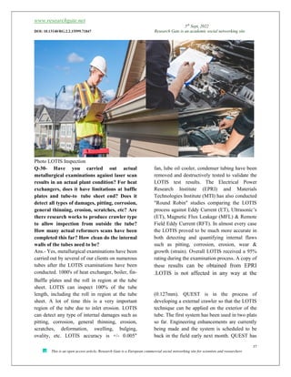
Q-29-How does the results of the LOTIS
inspection compare with metallographic
samples in reformer tubes to confirm
remaining life?
Do you plan to include any other NDE
method with the LOTIS system since no one
36. www.researchgate.net
5th
Sept, 2022
DOI: 10.13140/RG.2.2.15599.71847 Research Gate is an academic social networking site
36
This is an open access article, Research Gate is a European commercial social networking site for scientists and researchers
NDE technique will provide a comprehensive
assessment of tubes?
Ans.- Steam reformers are critical assets to
many refining, chemical and syngas plants, and
one of the most challenging assets to maintain
and operate. Common problems in reformer
operations directly affect reformer tube life and
lead to premature tube failure, pigtail failure,
and damage to the header and convection
section. For the first four years that LOTIS is
applied to detect and quantify creep strain
damage, it was only applied at the plants which
were owned and operated by the worlds largest
methanol producer (Methanex). During these
four years numerous tubes containing varying
degrees of strain damage (i.e. 0%, 1%, 2%, 3%,
4% growth) were removed from service and
destructively tested to provide cross correlation
and confirmation of the LOTIS results. Materials
such as HK-40, HP-Modified and Micro Alloy
were tested. The LOTIS results proved to be
extremely accurate when compared to the
metallurgical testing performed. This particular
client now utilizes the LOTIS technology
"exclusively" to test 100% of the tubes in their
SMR's for all of their methanol plants located
around the world. Since completion of the
studies conducted in conjunction with
Methanex, numerous plants around the world
have conducted comparison test of the LOTIS
against both Eddy Current (ET) and Ultrasonic’s
(UT). The LOTIS has always proven to be the
most accurate process while the two other
methods (ET & UT) have shown much
inconsistency in the test results. In nearly every
case where a plant has compared the various test
methods, LOTIS is now being utilized
exclusively due to its overwhelming accuracy
levels.
Benefits-
1. Minimizes unplanned shutdown risk due
to premature tube failure
2. Allows plant engineers to manage and
often extend tube life beyond 100,000
operating hours
3. Allows reformers to typically increase
production without compromising asset
integrity
4. Costs significantly less than an
unplanned outage
5. Provides better cost management of and
planning for future tube/catalyst
replacement
6. Reduces reformer downtime with fast
inspection process
7. Facilitates monitoring of tube life over
entire life cycle; other inspection
techniques are useful only at or very
near end of tube life which is often too
late for remnant life prediction or
effective tube replacement management
8. Baseline inspections at tube
manufacturing facilities and onsite prior
to startup for quality control
9. Review fitness-for-service and design of
all reformer components to API 579 and
ASME FFS-1/20-7; assessment of high
temperature components such as header
systems and inlet and outlet pigtails
10. Uses 3D elastic-plastic Finite Element
Analysis and Computational Fluid
Dynamics modeling of ancillary
equipment
37. www.researchgate.net
5th
Sept, 2022
DOI: 10.13140/RG.2.2.15599.71847 Research Gate is an academic social networking site
37
This is an open access article, Research Gate is a European commercial social networking site for scientists and researchers
Photo LOTIS Inspection
Q-30- Have you carried out actual
metallurgical examinations against laser scan
results in an actual plant condition? For heat
exchangers, does it have limitations at baffle
plates and tube-
to tube sheet end? Does it
detect all types of damages, pitting, corrosion,
general thinning, erosion, scratches, etc? Are
there research works to produce crawler type
to allow inspection from outside the tube?
How many actual reformers scans have been
completed this far? How clean do the internal
walls of the tubes need to be?
Ans.- Yes, metallurgical examinations have been
carried out by several of our clients on numerous
tubes after the LOTIS examinations have been
conducted. 1000's of heat exchanger, boiler, fin-
fan, lube oil cooler, condenser tubing have been
removed and destructively tested to validate the
LOTIS test results. The Electrical Power
Research Institute (EPRI) and Materials
Technologies Institute (MTI) has also conducted
"Round Robin" studies comparing the LOTIS
process against Eddy Current (ET), Ultrasonic’s
(ET), Magnetic Flux Leakage (MFL) & Remote
Field Eddy Current (RFT). In almost every case
the LOTIS proved to be much more accurate in
both detecting and quantifying internal flaws
such as pitting, corrosion, erosion, wear &
growth (strain). Overall LOTIS received a 95%
rating during the examination process. A copy of
these results can be obtained from EPRI
.LOTIS is not affected in any way at the
Baffle plates and the roll in region at the tube
sheet. LOTIS can inspect 100% of the tube
length, including the roll in region at the tube
sheet. A lot of time this is a very important
region of the tube due to inlet erosion. LOTIS
can detect any type of internal damages such as
pitting, corrosion, general thinning, erosion,
scratches, deformation, swelling, bulging,
ovality, etc. LOTIS accuracy is +/- 0.005"
(0.127mm). QUEST is in the process of
developing a external crawler so that the LOTIS
technique can be applied on the exterior of the
tube. The first system has been used in two plats
so far. Engineering enhancements are currently
being made and the system is scheduled to be
back in the field early next month. QUEST has
38. www.researchgate.net
5th
Sept, 2022
DOI: 10.13140/RG.2.2.15599.71847 Research Gate is an academic social networking site
38
This is an open access article, Research Gate is a European commercial social networking site for scientists and researchers
applied the LOTIS to inspect over 100,000 tubes
in reformers around the world. An average of
40-50 reformers at different plants are being
inspected annually. When applying the LOTIS
to inspect reformer tubes there is typically no
cleaning required? Only two (2) reformers to
date have had to have any cleaning performed
due to catalyst being bound inside the tube as a
result of solids being carried over from the
upstream boiler.
39. www.researchgate.net
5th
Sept, 2022
DOI: 10.13140/RG.2.2.15599.71847 Research Gate is an academic social networking site
39
This is an open access article, Research Gate is a European commercial social networking site for scientists and researchers
Photo-Quest Services.
Q-31- Is it possible to use this technique to determine the degree of damage in the metal of a
transfer line exit a reformer in substitution of other inspection techniques? How do you compare
the cost of using this technique vis a vis other inspection methods?
Ans,- The LOTIS is capable of inspecting tubing or piping with internal diameter (ID) rages of 0.440"
(11mm) to 6" (152mm). The maximum length of the tube or pipe can be up to 70' (21 meters). If the
transfer line contained sufficient access to the ID bore and met these two other criteria's then it could be
applied. LOTIS cost is very comparable to the external crawler (ET and UT) processes.
Ans.-
40. www.researchgate.net
5th
Sept, 2022
DOI: 10.13140/RG.2.2.15599.71847 Research Gate is an academic social networking site
40
This is an open access article, Research Gate is a European commercial social networking site for scientists and researchers
Splitting a mole of liquid water to produce a
mole of hydrogen at 25°C requires 285.8 kJ
of energy—237.2 kJ as electricity and 48.6
kJ as heat; there is no way around this fact.
41. www.researchgate.net
5th
Sept, 2022
DOI: 10.13140/RG.2.2.15599.71847 Research Gate is an academic social networking site
41
This is an open access article, Research Gate is a European commercial social networking site for scientists and researchers
In PEM and alkaline electrolysis cells the
heat requirement is supplied from the extra
heat generated, due to internal resistance as
the electric and ionic currents flow through
the cell. This heat requirement is directly
traceable back to the electricity supplied. In
other words, 285.8 kJ—not 237.2 kJ—of
electricity is the minimum required to split
water in these cells. This translates into a
cell voltage of 1.481 volts, not the 1.229
volts used in calculating the theoretical
maximum electrical efficiency of a fuel cell.
The electrochemical potential (standard
potential) corresponding to the HHV is
1.481 V/cell as shown below. This
represents the thermo neutral voltage at
which hydrogen and oxygen are produced
with 100% thermal efficiency (i.e., no waste
heat produced from the reaction). This is
determined using Faraday’s Law, and
dividing the HHV (285,840 J/mole) by the
Faraday constant (F = 96,485 coulombs
mole-1) and the number of electrons needed
to create a molecule of hydrogen (z = 2).
This voltage, 1.481 volts, is required for
splitting liquid water. It is the voltage at
which an electrolysis cell operating at 25°C
can operate without producing excess heat.
(Practical cells operate above this voltage
and produce excess heat.) It also is the
voltage that corresponds to the HHV of
hydrogen and therefore represents a more
reasonable value to use when calculating
cell and stack voltage efficiency. The
formula for calculating the voltage
efficiency of a cell or cell stack thus
becomes the following-
A similar calculation can be performed for
water vapor using the LHV. The thermo
neutral voltage for splitting water vapor at
25°C is 1.253 volts.
Steam Electrolysis and High-Temperature
Cells The above discussion applies primarily
to electrolysis cells operating at
temperatures that are less than the boiling
point of water; these include the PEM and
alkaline electrolysis cells. There is a class of
high-temperature steam electrolysis cells
under
development, however, that operates in the
800° to 1,000°C temperature range, where
the thermodynamics are significantly
different. As the temperature climbs, the
LHV of hydrogen increases and the Gibbs
free energy decreases. At 1,000°C, for
example, the LHV of hydrogen is 249.2
J/mole and the Gibbs free energy for the
reaction is 179.9 kJ/mole. The water-
splitting reaction at 1,000°C can thus be
written as follows.
H2O (steam) + 179.9 kJ/mole electricity +
69.3 kJ/mole heat → H2 + ½ O2
The thermodynamic voltage for this
reaction—which corresponds to both the
open-circuit voltage for the solid oxide fuel
cell and the solid oxide electrolyzer cell—is
0.932 volts. The thermo neutral voltage for
the electrolysis reaction is 1.291 volts. These
high-temperature cells are considerably
more efficient in that they have lesser
internal resistance losses and improved
reaction kinetics as compared to their low-
temperature PEM counterparts.
It is well within the realm of possibility that
a practical high-temperature electrolysis cell
could operate below the thermo neutral
voltage. In this case, the heat requirement
must be made up by an external heat source.
A high-temperature electrolyzer operating at
42. www.researchgate.net
5th
Sept, 2022
DOI: 10.13140/RG.2.2.15599.71847 Research Gate is an academic social networking site
42
This is an open access article, Research Gate is a European commercial social networking site for scientists and researchers
1,000°C and 1.200 volts, for example, would
not generate sufficient heat via internal
resistance to keep the electrochemical
reaction going. As the cell operated, the
electrochemical reaction would withdraw
heat from the cell components and cool the
cell to the point that it ceases operating.
Therefore, to maintain temperature, sensible
heat must be supplied to the cell components
from an outside source. In the high-
temperature case, calculating the voltage
efficiency of the cell can be straightforward
and the thermodynamic voltage can be used.
In the case of global system efficiency,
however, both the electrical input and the
heat input from the external source must be
included, otherwise the calculation produces
a nonsensical answer and an efficiency that
is greater than 100%.
*************************************************************************************