1. Journal of the Science of Food and Agriculture J Sci Food Agric 86:1755–1768 (2006)
Review
Biomass for energy
Tony Bridgwater∗
Bio-Energy Research Group, Aston University, Birmingham B4 7ET, UK
Abstract: Bio-energy is now accepted as having the potential to provide the major part of the projected renewable
energy provisions of the future as biofuels in the form of gas, liquid or solid fuels or electricity and heat.
There are three main routes to providing these biofuels – thermal conversion, biological conversion and physical
conversion – all of which employ a range of chemical reactor configurations and designs. This review focuses on
thermochemical conversion processes for their higher efficiencies, lower costs and greater versatility in providing
a wide range of energy, fuel and chemical options. The technologies of gasification and fast pyrolysis are described,
particularly the reactors that have been developed to provide the necessary conditions to optimise performance.
The primary products that can be derived as gas, liquid and solid fuels are characterised, as well as the secondary
products of electricity and/or heat, liquid fuels and a considerable number of chemicals.
2006 Society of Chemical Industry
Keywords: biomass; bioenergy; pyrolysis; gasification; biofuels
INTRODUCTION
Renewable energy is of growing importance in
responding to concerns over the environment and
the security of energy supplies. Biomass is unique in
providing the only renewable source of fixed carbon,
which is an essential ingredient in meeting many of
our fuel and consumer goods requirements. Wood and
annual crops and agricultural and forestry residues are
some of the main renewable energy resources available.
The biodegradable components of municipal solid
waste (MSW) and commercial and industrial wastes
are also significant bio-energy resources, although
particularly in the case of MSW, they may require
extensive processing before conversion. Biomass is
considered the renewable energy source with the
highest potential to contribute to the energy needs of
modern society for both the developed and developing
economies worldwide.1,2
In addition, energy from
biomass based on short rotation forestry and other
energy crops can contribute significantly towards
the objectives of the Kyoto Protocol in reducing
greenhouse gas emissions and alleviating problems
related to climate change.3
Biomass fuels and residues can be converted to
energy via the thermal, biological and mechanical or
physical processes summarised in Fig. 1.4
Thermal
processing currently attracts the most interest in
Europe and Canada while ethanol production is the
focus of attention in the USA for security of supply
reasons. Gasification has traditionally received the
most RD&D support as it offers potentially higher
efficiencies compared with combustion. Fast pyrolysis
is still at a relatively early stage of development but
offers the benefits of a liquid fuel with concomitant
advantages of easy storage and transport as well as
comparable higher power generation efficiencies at the
smaller scales of operation that are likely to be achieved
from bio-energy systems compared to fossil-fuelled
systems. Combustion systems are widely available
at domestic, small industrial and utility scales;
biological conversion processes (fermentation and
digestion) and mechanical processing (e.g. vegetable
oils) are well established and are all commercially
offered with performance guarantees. This review
therefore focuses on the thermal conversion processes
of gasification and pyrolysis as they offer high
conversion efficiencies, potentially competitive costs,
and considerable flexibility in scale of operation and
range of products.
The key difference between thermal and biological
conversion is that biological conversion gives single
or specific products such as ethanol or biogas
(which contains up to 60% methane) and is a slow
process, typically taking hours, days, weeks (anaerobic
fermentation and farm digestion) or years (landfill gas
by digestion) for reactions to be completed. Thermal
conversion gives multiple and often complex products,
with catalysts often used to improve the product
quality or spectrum, and takes place in very short
reaction times of typically seconds or minutes. Table 1
summarises some of the main products that can be
obtained by processing biomass.
A commercial process for realisation of energy and
fuel products from biomass comprises a biomass
production system and five main stages in the
conversion plant:4
1 Production of biomass as a short rotation coppice,
such as willow; forest residues; annually harvested
∗
Correspondence to: Tony Bridgwater, Bio-Energy Research Group, Aston University, Birmingham B4 7ET, UK
E-mail: bridgwav@email.aston.ac.uk
(Received 20 December 2005; revised version received 22 March 2006; accepted 23 June 2006)
Published online 31 July 2006; DOI: 10.1002/jsfa.2605
2006 Society of Chemical Industry. J Sci Food Agric 0022–5142/2006/$30.00
2. T. Bridgwater
Combustion
Electricity
Transport
fuels etc
Heat
Chemicals
Pyrolysis
Gasification
Fermentation
Digestion
Mechanical
Ethanol
Bio-gas
Rape oil
Heat
Thermal
conversion
Biological
conversion
Mechanical
conversion
Product Market
Fuel gas
Bio-oil
Figure 1. Conversion processes, products and applications.
Table 1. Major products from biomass conversion4
Product
Biological
processing
Physical
processing
Thermal
processing
Fuels
Additives
√ √ √
Alcohols
√ √
Charcoal
√
Diesel-type fuels
√
Fischer–Tropsch
liquids
√
Fuel oil
√
Gas
√ √
Gasoline
√
Hydrogen
√ √
Chemicals
Acetone
√
Activated carbon
√
Butanol
√
Ethanol
√ √
Fertilisers
√ √
Fine chemicals
√ √ √
Food additives
√ √
Hydrogen
√ √
Methane
√ √
Methanol
√
Resins
√
crops, such as miscanthus; and agricultural residues,
such as straw. This includes harvesting, in-field
processing such as chipping, and transport to the
conversion plant
2 Feed reception, storage, handling and pre-treatment
to prepare the biomass for the subsequent conver-
sion process
3 Conversion of solid biomass to a more usable form
of energy by means such as gasification or pyrolysis
4 Primary product refining or clean-up
5 Conversion of the primary product to a marketable
end-product such as electricity, heat, liquid biofuels
or chemicals
BIOMASS RESOURCES
Biomass is a diffuse resource, arising over very
large areas, and thus requiring large areas of land
with substantial logistical problems in collection and
transport as well as high costs. Typically, a sustainable
crop of 10 dry t ha−1
y−1
of woody biomass can be
produced in northern Europe, rising to perhaps 15 or
maybe 20 dry t hamiknus;1 y−1
for energy crops
in southern Europe. Thus an area of 1 km2
or
100 ha will produce 1000 dry t y−1
, enough for a power
output of 150 kWe at low conversion efficiencies, or
300 kWe at high conversion efficiencies. It is therefore
difficult to visualise power generation plants based
on indigenous biomass production much bigger than
around 30–40 MWe anywhere in Europe and even
these will require a planted area of around 100 km2
.
A further complication with almost all forms of
biomass is their seasonality: forestry and coppiced
crops can only be harvested during the winter months,
and energy crops and agricultural residues are even
more seasonal, typically growing for a only few months
a year. Extensive provision for storage thus has to be
made. One solution to this problem is a multi-fuel
system and increasing efforts are under way to develop
processes that can handle a number of different fuels,
either mixed or separately.5
The current view is that
even these plants are limited in size, with a typical plant
size of 5–15 MWe likely to dominate the market in the
short term. However, in locations where extensive
industrial operations are located close to managed
forests, it is technically feasible and economically
attractive to install large-scale bio-energy combined
heat and power (CHP) plants and burn the process
1756 J Sci Food Agric 86:1755–1768 (2006)
DOI: 10.1002/jsfa
3. Biomass for energy
residues to provide heat for the local industry. Biomass
and agricultural wastes are very similar in their arisings,
with most European industries individually producing
comparable quantities of material, although overall
regional and national totals may be substantial.
THERMAL CONVERSION PROCESSES
There are three main thermal processes – pyrolysis,
gasification and combustion – available for converting
biomass to a more useful energy form. Figure 2 sum-
marises their products and applications. Combustion
is already a well-established commercial technology
with applications in most industrialised and devel-
oping countries and development is concentrated on
resolving environmental problems. Combustion is well
established and widely practised with many examples
of dedicated plant and co-firing applications.6
Gasification
Fuel gas can be produced from biomass and related
materials either by partial oxidation to give a mixture
of carbon monoxide, carbon dioxide, hydrogen and
methane with nitrogen if air is used as the oxidant, or
by steam or pyrolytic gasification. Table 2 summarises
the main products in each case.
The process of gasification is a sequence of
interconnected reactions: the first step, drying, is a
relatively fast process. The second step, pyrolysis, is
also relatively fast but it is a complex process that
gives rise to the tars that cause so many problems
in gasification processes. Pyrolysis occurs when a
solid fuel is heated to 300–500 ◦
C in the absence
of an oxidising agent, giving a solid char, condensable
hydrocarbons or tar and gases. The relative yields
of char, liquid and gas mainly depend on the rate of
heating and the final temperature, and this is discussed
later in the section on fast pyrolysis. In gasification by
partial oxidation, both the gas and liquid and solid
products of pyrolysis then react with the oxidising
agent – usually air, although oxygen can be used – to
give the permanent gases CO, CO2, H2, and lesser
quantities of hydrocarbon gases. In steam or pyrolytic
gasification, the char is burned in a secondary reactor
to reheat the hot sand which provides the heat for the
gasification.4
The composition of the gas from char gasification
and partial oxidation of the other pyrolysis products
is influenced by many factors, including feed com-
position, water content, reaction temperature and the
extent of oxidation of the pyrolysis products. However,
the overall composition is essentially the equilibrium
composition of the C–H–O system at the temperature
of gasification. The alkali metals in the biomass act an
effective catalyst to promote the gasification reactions.
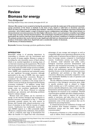
Status of biomass gasification technology
A number of gasifier configurations have been
developed. A recent survey of gasifier manufacturers
found that 75% of gasifiers offered commercially were
Efficiency
(%)
50
40
30
20
10
0
0.1 1 10 100 1000
Output (MWe)
Fluid bed
Updraft
Down-
draft
CFB
Entrained flow
Figure 3. Relationship between technology, scale and efficiency for
electricity production.
Turbine
Gasification
Pyrolysis
Combustion Heat
Fuel gas
Bio-oil
Electricity
CHP
Storage
Boiler
Engine
Chemicals
Char Charcoal
Heat
Primary
product
Conversion Market
Conversion
Storage
Figure 2. Thermal biomass conversion processes.
J Sci Food Agric 86:1755–1768 (2006) 1757
DOI: 10.1002/jsfa
4. T. Bridgwater
Table 2. Modes of thermal gasification4
Method Comments
Partial oxidation with air The main products are CO, CO2, H2, CH4, N2 and tar, giving a low heating value gas of
∼5 MJ m−3
. Utilisation problems can arise in combustion, particularly in gas turbines.
Partial oxidation with oxygen The main products are CO, CO2, H2, CH4 and tar (no N2), giving a medium heating value gas of
∼10–12 MJ m−3
. The cost of providing and using oxygen is compensated by a better quality
fuel gas. The trade-off is finely balanced.
Steam (pyrolytic) gasification The main products are CO, CO2, H2, CH4 and tar giving a medium heating value gas of
∼15–20 MJ m−3
. The process has two stages: the primary reactor produces gas and char, and
the sand and char is passed to a second reactor where the char is burned with air to reheat the
sand, which is then re-circulated to the first reactor to provide the heat for reaction. The gas
heating value is maximised due to a higher methane and higher hydrocarbon gas content, but at
the expense of lower overall efficiency due to loss of carbon in the second reactor.
Pressure Pressurised gasifiers operate under pressures of typically 15–50 bar. Both capital and operating
costs are significantly higher for pressurised operation, although these are to some extent
balanced by savings from reduced vessel and piping sizes, the avoidance of a gas compressor
for the gas turbine and higher efficiencies. Liquid feeding as bio-oil or slurry has significant
operational and economic advantages over solid biomass feeding. Pressurised operation is often
carried out with oxygen.
Oxygen Use of oxygen, usually with pressure operation, gives higher reaction temperatures and hence
lower tar levels; smaller and hence lower cost equipment from the absence of nitrogen; and
higher quality gas for both power generation and liquid fuel synthesis. There is, however, a
significant energy and financial cost associated with the use and supply of oxygen, from both its
procurement and the additional measures needed to mitigate hazards in handling and use.
downdraft, 20% were fluid beds (including circulating
fluid beds), 2.5% were updraft and 2.5% were
other types.7
The range of gasifier technologies and
their advantages and disadvantages are summarised
below4,7
and in Fig. 3.
Atmospheric downdraft gasifiers are attractive for
small-scale applications up to about 1.5 MWth as
there is a large market in both developed and
developing economies. While some configurations still
have problems with the effective removal of tar and
particulates, considerable progress has been made
and performance guarantees are increasingly offered.8
Biomass Engineering is one company that has made
considerable progress in this area with successful
operation of engines and microturbines.9
Atmospheric updraft gasifiers seem to have little
market attractiveness for power applications. While
this may be due to the high tar levels in the fuel
gas, recent developments in tar cracking have shown
that very low levels can be achieved from dedicated
thermal/catalytic cracking reactors downstream of the
gasifier. Another possible reason is that the upper
size of a single unit is around 2.5 MWe so larger
plant capacities require multiple units. There are
typically used for heat applications to maximise energy
efficiency.10
Atmospheric bubbling fluidised bed gasifiers have
proven to be reliable with a variety of feedstocks at
pilot scale and commercial applications in the small
to medium scale, up to about 25 MWth. They are
limited in their capacity size range as they have not
been significantly scaled up and the gasifier diameter
is significantly larger than that of circulating fluid beds
for the same feedstock capacity. On the other hand,
they are more economic for small to medium range
capacities. Their market attractiveness and technology
strength are thus relatively high, although there are
few operational examples.
Atmospheric circulating fluidised bed gasifiers have
proved very reliable with a variety of feedstocks and
are relatively easy to scale up from a few MWth
to 100 MWth. Even for capacities above 100 MWth,
there is confidence that the industry would be able to
provide reliable gasifiers. These gasifiers appear to be
the preferred system for large-scale applications and
these systems therefore have high market attractiveness
and are technically well proven. Examples include the
TPS (Termiska Processer AB) atmospheric process,11
and the Varnamo pressurised system.12
The most successful biomass gasifier currently
operating for power generation is the Güssing gasifier
in Austria which is an indirect gasification system
based on high temperature pyrolysis to generate a
medium heating value gas which is burned in an engine
to generate 2 MWe.13
This has completed more than
15 000 h of operation at the time of writing and has an
availability in excess of 90%.
Pressurised fluidised bed systems, either circulating
or bubbling, are considered of more limited market
attractiveness in the short term because of their
more complex installation and the additional costs
of construction of pressurised vessels. However,
pressurised systems have an advantage in integrated
combined cycle applications as the need to compress
the fuel gas prior to utilisation in the combustion
chamber of the gas turbine is avoided. Pressurised
systems are often used with oxygen as the oxidant
to improve the gas quality. There is, however, a
significant energy and financial cost associated with the
use and supply of oxygen, from both its procurement
1758 J Sci Food Agric 86:1755–1768 (2006)
DOI: 10.1002/jsfa
5. Biomass for energy
and the additional measures needed to mitigate
hazards in handling and use.
Very large scale gasification systems currently
being considered for processing millions of tonnes
of biomass a year would probably be pressurised
oxygen blown systems. There are logistical problems
of biomass supply that require resolution, but are
essential for economic synthesis of transport fuels.
These technologies would also be applied to pyrolysis
liquid gasification, when liquefaction of biomass
would reduce the handling and transport costs of
solid biomass and simply the gasification process.
Consideration is also being given to co-gasification
of biomass with coal and extensive trials have already
demonstrated the feasibility of this approach.
Fuel gas quality
The fuel gas quality requirements, for turbines and
liquid fuel synthesis in particular, are very high;
Table 3 gives some suggested figures for common
gasifiers.14
Tar is a particular problem and remains
the most significant technical barrier. There are two
basic ways of destroying tars, both of which have been
and continue to be extensively studied:15
• Catalytic cracking using, for example, dolomite or
nickel
• Thermal cracking, for example by partial oxidation
or direct contact
The gas is very costly to store or transport so it has to be
used immediately. Hot gas efficiencies for the gasifier
(total energy in the raw product gas as a fraction of
the energy in the feed) can be as high as 95–97% for
close-coupled turbine and boiler applications, and up
to 85% for cold gas efficiencies. In power generation
using combined cycle operation, efficiencies of up to
50% for the largest installations have been proposed,
reducing to 35% for smaller applications.
Gas clean-up
Gases formed by gasification will be contaminated
by some or all of the constituents listed in Table 4.
The level of contamination will vary depending on the
gasification process and the feedstock. Gas cleaning
must be applied to prevent erosion, corrosion and
environmental problems in downstream equipment.4
Applications of product gas
Figure 4 summarises the range of fuel, electricity
and chemical products that can be derived from
the product gas. Medium heating value gas from
steam or pyrolytic gasification, or from oxygen
gasification, is better suited to synthesis of transport
fuels and commodity chemicals because of the
absence of diluent nitrogen, which would pass through
unchanged but reduce process efficiency and increase
costs. The exception is ammonia synthesis, where the
nitrogen content derived from air gasification can be
utilised in the ammonia synthesis process.
Transport fuels and other chemicals
As biomass is the only renewable source of fixed
carbon, there is considerable interest in the production
of transport fuels and other commodity chemicals
Table 3. Typical product gas characteristics from different gasifiers14
Gas composition, dry, vol% Gas quality
H2 CO CO2 CH4 N2 HHV∗ (MJ N−1 m3) Tars Dust
Fluid bed air-blown 9 14 20 7 50 5.4 Fair Poor
Updraft air-blown 11 24 9 3 53 5.5 Poor Good
Downdraft air-blown 17 21 13 1 48 5.7 Good Fair
Downdraft oxygen 32 48 15 2 3 10.4 Good Good
Twin fluid bed 31 48 0 21 0 17.4 Fair Poor
Pyrolysis for comparison 40 20 18 21 1 13.3 Poor Good
∗ HHV: higher heating value.
Table 4. Fuel gas contaminants and their problems14
Contaminant Examples Problems Solution
Tars Refractive aromatics Clogs filters Difficult to burn
Deposits internally
Tar cracking thermally or catalytically,
or tar removal by scrubbing
Particulates Ash, char, fluidised bed
material
Erosion Filtration, scrubbing
Alkali metals Sodium, potassium
compounds
Hot corrosion Cooling, condensation, filtration,
adsorption
Fuel-bound nitrogen Mainly ammonia and HCN NOx formation Scrubbing, Selective catalytic removal
(SCR)
Sulfur, chlorine HCl, H2S Corrosion emissions Lime or dolomite, scrubbing,
absorption
J Sci Food Agric 86:1755–1768 (2006) 1759
DOI: 10.1002/jsfa
6. T. Bridgwater
MHV gas
Turbine
Engine
Boiler
Gasification
LHV gas Electricity
Steam or
oxygen
Air
Conversion
Transport
fuels etc
Fuel cell
Heat
Synthesis
Chemicals
Co-firing
Ammonia and
fertilisers
Figure 4. Applications for biomass gasification systems. MHV, medium heating value, typically 15 MJ/Nm3; LHV, low heating value, typically 5
MJ/Nm3
.
Gasification,
clean-up,
conditioning
Bio-oil
or
slurry
Methanol synthesis
+ MTG or MOGD
Solid
biomass
Hydrocarbon
synthesis
Transport
fuels
Refining
Chemicals
Electricity
Figure 5. Transport fuels via biomass gasification. MTG, methanol to gasoline; MOGD, methanol to olefins, gasoline and diesel.
through synthesis gas or syngas, as it is usually
known. Syngas is a mixture of carbon monoxide
(CO) and hydrogen (H2). There are usually other
components arising from gasification such as carbon
dioxide (CO2), methane (CH4), higher hydrocarbons
such as ethylene and ethane, propane and propylene,
and nitrogen from air gasification. Generally these act
as diluents, but different generic and specific processes
have different levels of tolerance for each component.
There will also be trace contaminants containing
sulfur (e.g. H2S), chlorine (e.g. HCl, COCl) and
nitrogen (e.g. NH3) in a range of compounds. The
concentrations of these trace components will usually
require reduction to a few parts per million for most
catalyst systems used in synthesising alcohols and
hydrocarbons, and each catalyst has its own limitations
and tolerances.
Either solid biomass can be gasified, which for
European-derived biomass will tend to limit the size of
plant to the availability of biomass unless considerable
biomass is imported, or bio-oil from fast pyrolysis can
be gasified which has a lower overall efficiency but
enables the necessary economies of scale to be realised
in the downstream synthesis of transport fuels and
chemicals. Gasification of bio-oil is also potentially
lower cost as it is easier to feed a liquid into a
pressurised gasifier than solid biomass.
Syngas provides the raw material for the produc-
tion of virtually every fuel and chemical in use today,
including conventional and unconventional transport
fuels, commodity chemicals and speciality chemicals.
Some of the possibilities for production of hydrocar-
bon transport fuels are shown in Fig. 5, which are of
considerable topical significance.
PYROLYSIS
Pyrolysis is thermal decomposition occurring in the
absence of oxygen. It is also always the first step in
combustion and gasification, but in these processes
Table 5. Typical product yields (dry wood basis) obtained by different modes of pyrolysis of wood
Mode Conditions
Liquid
(%)
Char
(%)
Gas
(%)
Fast Moderate temperature, around 500 ◦C, Short hot vapour residence time, ∼1 s 75 12 13
Intermediate Moderate temperature, around 500 ◦C, Moderate hot vapour residence time ∼10–20 s 50 20 30
Slow (carbonisation) Low temperature, around 400 ◦C, very long residence time 30 35 35
Gasification High temperature, around 800 ◦C, long residence times 5 10 85
1760 J Sci Food Agric 86:1755–1768 (2006)
DOI: 10.1002/jsfa
7. Biomass for energy
it is followed by total or partial oxidation of the
primary products. Lower process temperatures and
longer vapour residence times favour the production
of charcoal. High temperatures and longer residence
times increase biomass conversion to gas, and
moderate temperatures and short vapour residence
time are optimum for producing liquids. Table 5
indicates the product distribution obtained from
different modes of pyrolysis. Fast pyrolysis for liquids
production is currently of particular interest because
liquids can be stored and transported more easily and
at lower cost than solid biomass. A number of reviews
have been published to which reference should be
made for detailed information.16–19
Fast pyrolysis occurs in a time of a few seconds
or less. Therefore heat and mass transfer processes
and phase transition phenomena, as well as chemical
reaction kinetics, play important roles. The critical
issue is to bring the reacting biomass particles to
the optimum process temperature and minimise their
exposure to the intermediate (lower) temperatures that
favour formation of charcoal. One way this objective
can be achieved is by using small particles, for example
in the fluidised bed processes that are described later.
Another possibility is to transfer heat very fast only
to the particle surface that contacts the heat source
as applied in ablative pyrolysis. A critical technical
challenge in every case is heat transfer to the reactor
in commercial systems.
Principles of fast pyrolysis
In fast pyrolysis, biomass decomposes to generate
mostly vapours and aerosols and some charcoal. After
cooling and condensation, a dark brown mobile liquid
is formed which has a heating value about half that
of conventional fuel oil. While it is related to the
traditional pyrolysis processes for making charcoal,
fast pyrolysis is an advanced process, with carefully
controlled parameters to give high yields of liquid.
The essential features of a fast pyrolysis process for
producing liquids are:
• Very high heating and heat transfer rates at the
reaction interface, which usually requires a finely
ground biomass feed
• Carefully controlled pyrolysis reaction temperature
of around 500 ◦
C and vapour phase temperature
of 400–450 ◦
C; the effect of temperature on yields
and product spectrum is discussed in the section on
pyrolysis liquid below
• Short hot vapour residence times of typically less
than 2 s
• Rapid cooling of the pyrolysis vapours to give the
bio-oil product
The main product, bio-oil, is obtained in yields
of up to 75% wt on a dry-feed basis, together with
by-product char and gas, which are used within the
process to provide the process heat requirements so
there are no waste streams other than flue gas and ash.
A fast pyrolysis process includes drying the feed to
typically less than 10% water in order to minimise the
water in the product liquid oil (although up to 15%
can be acceptable), grinding the feed (to around 2 mm
particle size in the case of fluid bed reactors) to give
sufficiently small particles to ensure rapid reaction,
pyrolysis reaction, separation of solids (char), and
quenching and collection of the liquid product (bio-
oil).
Virtually any form of biomass can be considered for
fast pyrolysis. While most work has been carried out
on wood because of its consistency and comparability
between tests, nearly 100 different biomass types
have been tested by many laboratories, ranging from
agricultural wastes such as straw, olive pits and
nut shells to energy crops such as miscanthus and
sorghum, forestry wastes such as bark and solid wastes
such as sewage sludge and leather wastes.
A typical fast pyrolysis process is depicted in Fig. 6
showing the necessary preparation steps, alternative
reactors and product collection.
Reactors
At the heart of a fast pyrolysis process is the reactor.
Although it probably represents, at most only about
10–15% of the total capital cost of an integrated
system, most research and development has focused on
the reactor, although increasing attention is now being
paid to control and improvement of liquid quality
and improvement of collection systems. The rest of
the process consists of biomass reception, storage
and handling, biomass drying and grinding, product
collection, storage and, when relevant, upgrading. The
key aspects of these peripheral steps are described later.
A comprehensive survey of fast pyrolysis processes for
BIOMASS BIO-OIL
Cool and
collect
Pyrolysis
Fluid bed
CFB
Transported bed
Rotating cone
Entrained flow
Ablative
etc Char
Drying
to <10% water
Gas
Grinding
To < ~ 3mm
Char
separation
Figure 6. Conceptual fast pyrolysis process.
J Sci Food Agric 86:1755–1768 (2006) 1761
DOI: 10.1002/jsfa
8. T. Bridgwater
liquids production that have been built and tested in
the last 10–15 years has been published.17
Bubbling fluid beds
Bubbling fluid beds – usually referred to as just fluid
beds as opposed to circulating fluid beds – have
the advantages of a well understood technology
that is simple in construction and operation, good
temperature control and very efficient heat transfer
to biomass particles arising from the high solids
density. Fluid-bed pyrolysers give good and consistent
performance with high liquid yields of typically
70–75% wt from wood on a dry-feed basis. Small
biomass particle sizes of less than 2–3 mm are needed
to achieve high biomass heating rates, and the rate of
particle heating is usually the rate-limiting step.
Residence time of solids and vapours is controlled
by the fluidising gas flow rate and is higher
for char than for vapours. As char acts as an
effective vapour cracking catalyst at fast pyrolysis
reaction temperatures, rapid and effective char
separation/elutriation is important. This is usually
achieved by ejection and entrainment followed by
separation in one or more cyclones so careful design of
sand and biomass/char hydrodynamics is important.
The earliest pioneering work on fast pyrolysis
was carried out at the University of Waterloo by
Scott and colleagues20–22
who published extensively.
The largest plant currently operating is that by
Dynamotive in West Lorne, Ontario, Canada, which
has a demonstration plant that produces 100 t d−1
of
dry biomass feed, with plans for further plants up to
400 t/d.23
A 2.5 MWe gas turbine is also provided on
site for generation of power locally and for export to
the grid.
Circulating fluid beds and transported bed
Circulating fluid beds (CFBs) have many of the
features of bubbling beds described above, except
that the residence time of the char is almost the
same as for vapours and gas, and the char is more
attrited due to the higher gas velocities, which can
lead to higher char contents in the collected bio-
oil. An added advantage is that CFBs are potentially
suitable for very large throughputs even though the
hydrodynamics are more complex – this technology is
widely used at very high throughputs in the petroleum
and petrochemical industries. However, heat transfer
at higher throughputs has not been demonstrated
and offers some challenges.4
Heat supply is usually
from recirculation of heated sand from a secondary
char combustor, which can be either a bubbling or
circulating fluid bed. In this respect the process is
similar to a twin fluid-bed gasifier except that the
reactor (pyrolyser) temperature is much lower and the
closely integrated char combustion in a second reactor
requires careful control to ensure that the temperature
and heat flux match the process and feed requirements.
A variation on the transported bed is the rotating
cone reactor, invented at the University of Twente24
and implemented by BTG in the Netherlands. In this
configuration, the transport is effected by centrifugal
forces rather than gas. A 50 t d−1
plant has been built
in Malaysia and was commissioned in summer 2005.
Ablative pyrolysis
Ablative pyrolysis is substantially different in concept
compared with other methods of fast pyrolysis.4
In all
the other methods, the rate of reaction is limited
by the rate of heat transfer through the biomass
particles, which is why small particles are required.
The mode of reaction in ablative pyrolysis is like
melting butter in a frying pan – the rate of melting
can be significantly enhanced by pressing the butter
down and moving it over the heated pan surface. In
ablative pyrolysis, heat is transferred from the hot
reactor wall to ‘melt’ wood that is in contact with
it under pressure. The pyrolysis front thus moves
unidirectionally through the biomass particle. As the
wood is mechanically moved away, the residual oil
film both provides lubrication for successive biomass
particles and also rapidly evaporates to give pyrolysis
vapours for collection in the same way as other
processes. The rate of reaction is strongly influenced by
pressure, the relative velocity of the wood and the heat
exchange surface and the reactor surface temperature.
The key features of ablative pyrolysis are therefore as
follows:
• High pressure of particle on hot reactor wall,
achieved due to centrifugal force
• High relative motion between particle and reac-
tor wall
• Reactor wall temperature less than 600 ◦
C
As reaction rates are not limited by heat transfer
through the biomass particles, large particles can be
used and, in principle, there is no upper limit to the
size that can be processed. In fact, the process is
limited by the rate of heat supply to the reactor rather
than the rate of heat absorption by the pyrolysing
biomass, as in other reactors. There is no requirement
for inert gas, so the processing equipment is smaller
and potentially lower cost. However, the process is
surface-area-controlled so scaling is more costly and
the reactor is mechanically driven, and is thus more
complex. A 50 t d−1
demonstration plant has recently
started operating in north Germany25
and a small
research unit operates at Aston University.26
Entrained flow
Entrained flow fast pyrolysis is, in principle, a simple
technology, but most developments have not been
as successful as had been hoped, mostly because of
the poor heat transfer between a hot gas and a solid
particle. High gas flows are required to effect sufficient
heat transfer, which requires large plant sizes and
entails difficult liquid collection from the low vapour
partial pressure. Liquid yields have usually been lower
than fluid bed and CFB systems.
1762 J Sci Food Agric 86:1755–1768 (2006)
DOI: 10.1002/jsfa
9. Biomass for energy
By-products
Charcoal and gas are by-products, typically containing
about 25 and 5%, respectively, of the energy in the feed
material. The pyrolysis process itself requires about
15% of the energy in the feed, and of the by-products,
only the char has sufficient energy to provide this heat.
The heat can be derived by burning the gas and/or the
charcoal byproduct, More advanced configurations
could gasify the char to a (LHV) gas and then burn
the resultant gas more effectively to provide process
heat with the advantage that the alkali metals in the
char can be much better controlled and avoid potential
slagging problems from direct char combustion.
Pyrolysis liquid (bio-oil)
Crude pyrolysis liquid, or bio-oil, is dark brown and
approximates to biomass in elemental composition. It
is composed of a very complex mixture of oxygenated
hydrocarbons with an appreciable proportion of water
from both the original moisture and reaction product.
Solid char may also be present. The product spectrum
from aspen wood and the high dependence on
temperature is shown in Fig. 7.
The liquid is formed by rapidly quenching and
thus ‘freezing’ the intermediate products of flash
degradation of hemicellulose, cellulose and lignin.
The liquid thus contains many reactive species,
which contribute to its unusual attributes. Bio-
oil can be considered a micro-emulsion in which
the continuous phase is an aqueous solution of
holocellulose decomposition products, which stabilises
the discontinuous phase of pyrolytic lignin macro-
molecules through mechanisms such as hydrogen
bonding.
Fast pyrolysis liquid has a higher heating value of
about 16–17 MJ kg−1
as produced with about 25% wt
water that cannot readily be separated. It is composed
of a complex mixture of oxygenated compounds
that provide both the potential and challenge for
utilisation. There are some important characteristics
of this liquid that are summarised in Tables 6 and 7
and are discussed briefly below, of which the most
0
10
20
30
40
50
60
70
550
450 475 500 525 575 600 625 650 675
425
Reactor temperature (°C)
Yield
on
dry
feed
(wt%)
Organics
Char
Gas
Water
Figure 7. Variation of products from aspen poplar with
temperature.27
Table 6. Typical properties of wood-derived crude bio-oil
Physical property Typical value
Moisture content 25%
pH 2.5
Specific gravity 1.20
Elemental analysis
C 56%
H 6.5%
O 37.5%
N 0.1%
Ash 0%
∗HHV as produced 17 MJ kg−1
Viscosity (40 ◦C and 25% water) 50 cP
Solids (char) 0.1%
Vacuum distillation residue up to 50%
∗ HHV: higher heating value.
Table 7. Characteristics of wood-derived crude bio-oil
• Liquid fuel
• Ready substitution for conventional fuels in many stationary
applications such as boilers, engines, turbines
• Heating value of 17 MJ kg−1
at 25% wt water, is about
40% that of fuel oil/diesel
• Does not mix with hydrocarbon fuels
• Not as stable as fossil fuels
• Quality needs definition for each application
significant is that it will not mix with any conventional
hydrocarbon-based fuels.
Pyrolysis oil typically is a dark brown, free-flowing
liquid. Depending on the initial feedstock and the
mode of fast pyrolysis, the colour can be almost
black through dark red–brown to dark green, being
influenced by the presence of micro-carbon in the
liquid and chemical composition. Hot vapour filtration
gives a more translucent red–brown appearance owing
to the absence of char. High nitrogen content can
impart a dark green tinge to the liquid.
The liquid has a distinctive odour – an acrid smoky
smell due to the low molecular weight aldehydes
and acids – which can irritate the eyes on prolonged
exposure. The liquid contains several hundred
different chemicals in widely varying proportions,
ranging from formaldehyde and acetic acid to complex
high molecular weight phenols, anhydrosugars and
other oligosaccharides.
The liquid contains varying quantities of water,
which forms a stable single-phase mixture, ranging
from about 15 wt% to an upper limit of about 30–50
wt% water, depending on the feed material, how it was
produced and subsequently collected. A typical feed
material specification is a maximum of 10% moisture
in the dried feed material, as both this feed moisture
and the water of reaction from pyrolysis, typically
about 12% based on dry feed, both report to the liquid
product. Pyrolysis liquids can tolerate the addition
of some water, but there is a limit to the amount
of water, which can be added to the liquid before
phase separation occurs, in other words the liquid
J Sci Food Agric 86:1755–1768 (2006) 1763
DOI: 10.1002/jsfa
10. T. Bridgwater
cannot be dissolved in water. The addition of water
reduces viscosity, which is useful; reduces heating
value, which means that more liquid is required to
meet a given duty; and can improve stability. The
effect of water is therefore complex and important.
It is miscible with polar solvents such as methanol
and acetone, but is totally immiscible with petroleum-
derived fuels.
The density of the liquid is very high at around
1.2 kg L−1
, compared with light fuel oil at around
0.85 kg L−1
. This means that the liquid has about
42% of the energy content of fuel oil on a weight
basis, but 61% on a volumetric basis. This has
implications for the design and specification of
equipment such as pumps and atomisers in boilers
and engines.
Pyrolysis liquids cannot be completely vaporised
once they have been recovered from the vapour
phase. If the liquid is heated to 100 ◦
C or more to
try to remove water or distil off lighter fractions, it
rapidly reacts and eventually produces a solid residue
of around 50 wt% of the original liquid and some
distillate containing volatile organic compounds and
water. While bio-oil has been successfully stored for
several years in normal storage conditions in steel
and plastic drums without any deterioration that
would prevent its use in any of the applications
tested to date, it does change slowly with time, most
noticeably there is a gradual increase in viscosity.
Recent samples that have been distributed for testing
have shown substantial improvements in consistency
and stability.
Applications of bio-oil
Bio-oil can substitute for fuel oil or diesel in many
static applications including boilers, furnaces, engines
and turbines for electricity generation.28
Figure 8
summarises the possibilities. A range of chemicals
including food flavourings, specialities, resins,29
agri-
chemicals, fertilisers, and emissions control agents can
also be extracted or derived from bio-oil. At least 400 h
operation has been achieved on a 250 kWe specially
Liquid
Turbine
Engine
Boiler
Fast
pyrolysis
Charcoal
Electricity
Extraction
Conversion
Transport
fuels etc
Charcoal
applications
Upgrading
Chemicals
Gas
Co-firing Heat
Process
heat
Pyrolysis
heat
Figure 8. Applications for products of fast pyrolysis.
H2
Hydro-
treating
Zeolite
cracking
Hydrogen
separation
Chemicals
Electricity
Fast
pyrolysis
Gasification
Synthesis Transport
fuels
Refining
Slurry
Char
Liquid
Figure 9. Transport fuels via biomass pyrolysis.
1764 J Sci Food Agric 86:1755–1768 (2006)
DOI: 10.1002/jsfa
11. Biomass for energy
Gas
combustion
Gasification
Oil
combustion
Charcoal
Pyrolysis
Solid fuel
combustion
(Mixing)
Storage
Bio-oil
Fuel gas
Storage
Biomass
Fuel gas
Figure 10. Opportunities for co-processing biomass and biofuels in conventional heat and power applications.
modified dual-fuel engine and experience has been
gained on a modified 2.5 MWe industrial gas turbine.30
As noted above, upgrading bio-oil to transportation
fuels is feasible but not currently economic. A possible
route is shown in Fig. 9.
Co-firing and co-processing
Co-processing of biomass with conventional fuels is
potentially a very attractive option that enables full
economies of scale to be realised as well as reducing
the requirements for product quality and clean-up.6
The opportunities are summarised in Fig. 10. At
present, co-firing offers the best opportunities for
market penetration of biomass as the overall costs are
relatively low because the power cycle in the coal-fired
power plant is already there.
Almost all co-firing is based on addition of solid
biomass to the coal prior to combustion in the
boilers. There are a number of examples where the
biomass is first converted to a fuel gas via gasification,
which is directly burned in an existing coal-fired
boiler. Trials have also taken place of combustion
of fast pyrolysis liquids in both coal fired and gas
fired power stations. These latter options have the
advantage that the biomass residual ash is not mixed
with the coal ash, which has an existing market as a
construction material and can thus be recycled back to
the forest or field. In re-burning applications, (where
the fuel gas is introduced almost at the top of the
coal boiler), the environmental performance of the
power station is significantly improved, in addition to
the replacement of fossil fuels by renewable biomass
fuels.
BIOLOGICAL CONVERSION PROCESSES
Ethanol
In order to produce ethanol by fermentation, the
cellulose and hemicellulose in lignocelluloses need
to be hydrolysed to sugars prior to fermentation,
and both enzyme and acid hydrolysis are employed
for this purpose.31,32
Carbohydrates such as starch
also require hydrolysis. Only the cellulose in biomass
is conventionally converted to ethanol, although
increasing success is being obtained with conversion
of hemicellulose, which will improve conversion
efficiency and reduce costs. The lignin is a residue that
can be burned for process heat, particularly for ethanol
concentration, or further processed for production of
refinery feedstocks or aromatic chemicals. It is this
integration of energy, fuels and chemicals that is
increasingly considered as a biorefinery, which can
be simply explained as an optimised system of utilising
biomass in technical, economic, environmental and
social terms.
The overall efficiencies of ethanol production are
rather low, owing to the loss of about half the carbon
in holocellulose as carbon dioxide; the loss of the
carbon in lignin, which is not converted; and the need
to concentrate the dilute ethanol solution.
Fermentation is particularly suitable for materials
with high moisture content, as drying is not required.
Ethanol can be readily converted to ethyl tertiary
butyl ether (ETBE), which can be directly used
as a gasoline additive. Fermentation technology is
commercial and tends to be high cost unless subsidies
are applied and low efficiency unless credits are applied
to the by-products. After a lull in RD&D, there is
now renewed interest in bio-ethanol, with enzyme
hydrolysis in particular attracting more attention. A
substantial demonstration plant can be expected soon.
Currently there is little RD&D because the technology
is established and viability relies on financial support.
BP and DuPont announced an initiative in June
2006 to develop bio-butanol from fermentation of
suitable biomass feedstocks as an additive for transport
fuels, which offers improved properties compared to
ethanol.33
Biodiesel
Biodiesel is the ester formed by reacting vegetable oils
or animal fats with methanol or ethanol. Vegetable oil
can be recovered from oil seeds such as rape (canola
or colza), or other crops such as linseed, sunflower,
soy etc. The product in its raw form is unsuitable for
many applications because it is highly viscous and has
other deleterious properties, so the methyl or ethyl
ester is formed by esterification. However, there have
been limited attempts to use the cold-pressed oil as
transport fuel.
J Sci Food Agric 86:1755–1768 (2006) 1765
DOI: 10.1002/jsfa
12. T. Bridgwater
The most common product is rape methyl ester
(RME). The raw oil is recovered by pressing, usually
accompanied by solvent extraction to improve yields.
This raw oil is then subjected to esterification with
methanol or ethanol over a catalyst giving a lower
viscosity and more stable product and glycerine as
a by-product. The ester is entirely compatible with
diesel in use and applications and biodiesel is thus an
attractive renewable transport fuel.
The yield of vegetable oil per unit land area
is, however, very low at around 1–2 t ha−1
y−1
and
is accompanied by around 5–8 t ha−1
y−1
of solid
residues such as rape straw, which is not usually
utilised. The product cost is therefore high. The
conventional conversion technology is semi-batch but
simple and proven, but there have been a number
of recent developments of fully continuous processes
that can handle vegetable oils and waste oils and
fats. Animal fats and waste cooking oils can also be
processed in an analogous way and, while the scope
is limited due to limited raw material availability, this
route offers significant economic opportunities while
the waste materials continue to be available at low
cost.
Anaerobic digestion
Anaerobic digestion is microbial conversion of organic
materials to methane and carbon dioxide in the
absence of oxygen. The product gas from farm
digesters is typically around 60% methane, although
higher levels have been reported. The typical methane
content from landfill sites is lower at 50–55%.
Digestion is particularly suitable for residues with
high moisture contents, as drying is not required. The
biogas can be used for heat with minimal processing, or
for power generation in engines or turbines and (after
upgrading to methane quality by removal of carbon
dioxide and other components) in fuel cells or as
gaseous fuel for transport applications. This requires
increasingly stringent quality specifications. Landfill
sites tend to be very large and typically produce gas
over a 20–25 year life. Gas is collected through a
system of wells, which collect and pipe the gas to the
user.
The gas is wet and contains acid components which
require careful management to avoid or minimise
problems in using the gas for heat and/or power
production. As landfill gas collection is required in
many countries to comply with legislation to minimise
hazards, the additional costs of distributing gas to
users is very small, so landfill gas is an economically
attractive renewable energy resource. However, as
pressure grows to reduce land filling by legislation
in the European Union, this resource is expected
to reduce in the long term. On-farm or industrial
digesters using farm wastes, industrial food wastes and
household wastes are becoming more widely used for
smaller scale applications. The wastewater industry,
in particular, has successfully and effectively used
digestion for in-plant power generation for many years.
Dedicated digesters tend to be costly and inefficient
as well making a significant amount of solid residues
that must be disposed of. Thus small-scale digestion is
not often cost-effective. Although there is widespread
interest in anaerobic digestion for both waste disposal
and energy generation, economic opportunities are
limited to niche applications.
New developments in solid-state fermentation have
allowed the content of the dry solids of the substrate
to be as high as 30–35 wt%, compared with only
3–10 wt% for traditional liquid phase fermentation.
This increases biogas productivity by a factor of about
3, and reduces digester volumes. This technology
has found applications in the processing of the
biodegradable fraction of MSW or source-separated
waste. In all types of digestion, the carbon dioxide
component can be reduced or removed to give higher
quality gas, up to natural gas qualities. There is a
range of available technologies, including membrane
processes and conventional scrubbing processes,
according to the scale of operation. All are costly, and
careful assessment of the added value of the resultant
higher quality gas is needed. The purified methane can
either be used as transport fuel or added to a natural
gas pipeline.
BIOREFINERY
After many years of production of chemicals from bio-
oil, there is rapidly growing interest in the biorefinery
concept in which fuels and chemicals are optimally
produced by technical, economic, environmental and
social criteria.34
Recent examples of a biorefinery
include utilisation of heavy residues from liquid
smoke production for co-firing in a power station
and production of hydrogen by steam reforming of
the aqueous residues from recovery of phenolics for
resin production. The key feature and objective is
optimum utilisation of products, by-products and
wastes as shown in Fig. 11. Some of the alternatives
for achieving this optimum for production of transport
fuels and chemicals are shown in Fig. 12.
CONCLUSIONS
There is substantial and growing interest in thermal
processing of biomass for biofuels, to make both
energy and chemicals. Gasification and pyrolysis
are complementary processes that have different
market opportunities and should not be viewed
as competitors. In both technologies, there is
Biomass
Chemicals
Commodities
Fuels
By-products and wastes
Fast
pyrolysis
Secondary
processing
Tertiary
processing
Figure 11. Biorefinery concept.
1766 J Sci Food Agric 86:1755–1768 (2006)
DOI: 10.1002/jsfa
13. Biomass for energy
Pyrolysis
Distillation
Gasification Synthesis
Hydro-
processing
Biomass
Surplus
electricity
(waste) water
Ethanol
Transport fuels
Chemicals
Fuels
Chemicals
Transport fuels
Chemicals
Fermentation
Electrolysis
Lignin
H2
Wet gasification
Power and heat from
byproducts and waste
Figure 12. A biorefinery system with processing options for fuels and chemicals.
still considerable progress to be made in optimal
interfacing of conversion and utilisation of the primary
products from conversion, as well as the important
interface between biomass production and conversion
that has been largely left to market forces.
The main challenges lie first in bringing the thermal
conversion technologies closer to the power generation
or chemicals production processes, with both sides
of the interface moving to an acceptable middle
position, and second, in fully appreciating that, with
rare exceptions, bio-energy systems will always be
relatively small and must therefore be technically
and economically competitive at much smaller scales
of operation than the process and power generation
industries are used to handling.
REFERENCES
1 European Commission, Energy for the Future: Renewable Energy
Sources – White Paper for a Community Strategy and Action Plan.
Communication from the Commission, COM (97) 599, Final
of 26.11.97. EC, Brussels (1997).
2 IEA, World Energy Outlook 2000. IEA, Paris (2000).
3 IEA Bioenergy. The Role of Bioenergy in Greenhouse Gas
Mitigation, Position paper. IEA Bioenergy, New Zealand
(1998).
4 Bridgwater AV and Maniatis K, The production of biofuels by
the thermochemical processing of biomass, in Molecular to
Global Photosynthesis, ed. by Archer MD and Barber J. IC
Press, London UK, pp. 521–612 (2004).
5 Christou M, Fernandez J, Gosse G, Venturi G, Bridgwater A,
Scheurlen K, et al. Bio-energy chains from perennial crops in
South Europe, in Proceedings of the 13th Biomass for Energy
Conference, Paris, September 2004. Elsevier, Amsterdam.
6 Van Loo S and Koppejan J, Handbook of Biomass Combustion and
Co-firing. Twente University Press, The Netherlands (2003).
7 Knoef HAM, Inventory of Biomass Gasifier Manufacturers and
Installations, Final Report to European Commission, Contract
DIS/1734/98-NL. Biomass Technology Group B.V., Univer-
sity of Twente, Enschede. http://www.gasifiers.org/ (2000).
8 Lauer M, Identification of providers of small wood gasification
plants for implementation in Styria, Austria. Aston University
Birmingham, ThermalNet Newsletter 2:18–21 (2006).
9 Walker M, Jackson G and Peacocke GVC, Small-scale biomass
gasification: development of a gas cleaning system for power
generation, in Progress in Thermochemical Biomass Conver-
sion, ed. by Bridgwater AV. Blackwell Science, London,
pp. 441–451 (2001).
10 Kurkela E, PROGAS – Gasification and Pyrolysis R&D Pro-
gramme 1997–1999, in Proceedings Conference on Power Pro-
duction from Biomass III, Gasification & Pyrolysis R&D&D.
VTT, Espoo, Finland (2000).
11 Waldheim L, Morris M and Leal M, RLV, biomass power
generation: sugar cane bagasse and trash, in Progress in
Thermochemical Biomass Conversion, ed. by Bridgwater AV.
Blackwell Science, London, pp. 509–523 (2001).
12 Ståhl K, Neergaard M and Nieminen J, Final report: Värnamo
demonstration programme, in Progress in Thermochemical
Biomass Conversion, ed. by Bridgwater AV. Blackwell Science,
London, pp. 549–563 (2001).
13 Hofbauer H and Rauch R, Stoichiometric water consumption
of steam gasification by the FICFB–gasification process,
in Progress in Thermochemical Biomass Conversion, ed. by
Bridgwater AV. Blackwell Science, London, pp. 199–208
(2001).
14 Bridgwater AV, The technical and economic feasibility of
biomass gasification for power generation, Fuel 74:631–653
(1995).
15 Bridgwater AV, Catalysis in thermal biomass conversion, Appl
Catalysis A 116:5–47 (1994).
16 Bridgwater AV, Biomass fast pyrolysis. Thermal Sci 8:17–45
(2004).
17 Bridgwater AV, Renewable fuels and chemicals by thermal
processing of biomass. Chem Eng J 91:87–102 (2003).
18 Bridgwater AV and Peacocke GVC, Fast pyrolysis processes for
biomass. Renewable and Sustainable Energy Reviews 4:1–73
(1999).
19 Bridgwater AV, The production of biofuels and renewable
chemicals by fast pyrolysis of biomass. International Journal of
Global Energy Issues (2006).
20 Scott DS, Piskorz J and Radlein D, Liquid products from the
continuous flash pyrolysis of biomass. Ind Eng Chem Process
Des Dev 24:581–588 (1985).
21 Scott DS and Piskorz J, The flash pyrolysis of aspen poplar
wood. Can J Chem Eng 60:666–674 (1982).
22 Scott DS, Legge RL, Piskorz J, Majerski P and Radlein D, Fast
pyrolysis of biomass for recovery of speciality chemicals,
Developments in Thermochemical Biomass Conversion, ed. by
Bridgwater AV and Boocock DGB. Blackie Academic and
Professional, London, pp. 523–535 (1997).
23 Bridgwater AV, Sidwell A, Colechin M, Shanahan G and Shar-
man P, DTI Globalwatch Mission Report: Bioenergy – a
Scoping Mission to the USA and Canada, February/October
2005. UK DTI, London and PERA, Melton Mowbray, UK
(2006).
J Sci Food Agric 86:1755–1768 (2006) 1767
DOI: 10.1002/jsfa
14. T. Bridgwater
24 Prins W and Wagenaar BM, Review of rotating cone technology
for flash pyrolysis of biomass, in Biomass Gasification
and Pyrolysis, ed. by Kaltschmitt MK and Bridgwater
AV. CPL Scientific Ltd, Newbury, UK, pp. 316–326
(1997).
25 Meier D, Schoell S and Klaubert H, New developments in
ablative fast pyrolysis at PYTEC, Germany. Aston University
Birmingham, ThermalNet Newsletter 1:4 (2005).
26 Peacocke GVC and Bridgwater AV, Ablative plate pyrolysis
of biomass for liquids. Biomass and Bioenergy 7:147–154
(1994).
27 Scott DS and Piskorz J, The flash pyrolysis of aspen poplar
wood. Can J Chem Eng 60:666–674 (1982).
28 Czernik S and Bridgwater AV, Applications of biomass fast
pyrolysis oil. Energy and Fuel 18:590–598 (2004).
29 Amen-Chen C, Pakdel H and Roy C, Production of monomeric
phenols by thermochemical conversion of biomass: a review.
Bioresource Technology 79:277–299 (2001).
30 Leech J, Running a dual fuel engine on pyrolysis oil, in
Biomass Gasification and Pyrolysis, ed. by Kaltschmitt M and
Bridgwater AV. CPL Press, Newbury, pp. 495–497 (1997).
31 Wyman C, Handbook on Bioethanol: Production and Utilization,
Applied Energy Technology Series. Taylor and Francis Inc.,
New York, USA (1996).
32 US DOE, 21st Century Complete Guide to Biofuels and Bioenergy.
Department of Energy Alternative Fuel Research, Washington
DC, USA (2003).
33 BP Press Release, 20 June 2006.
34 Kamm B, Gruber PR and Kamm M, Biorefineries – Industrial
Processes and Producers. Wiley-VCH, Germany (2006).
1768 J Sci Food Agric 86:1755–1768 (2006)
DOI: 10.1002/jsfa