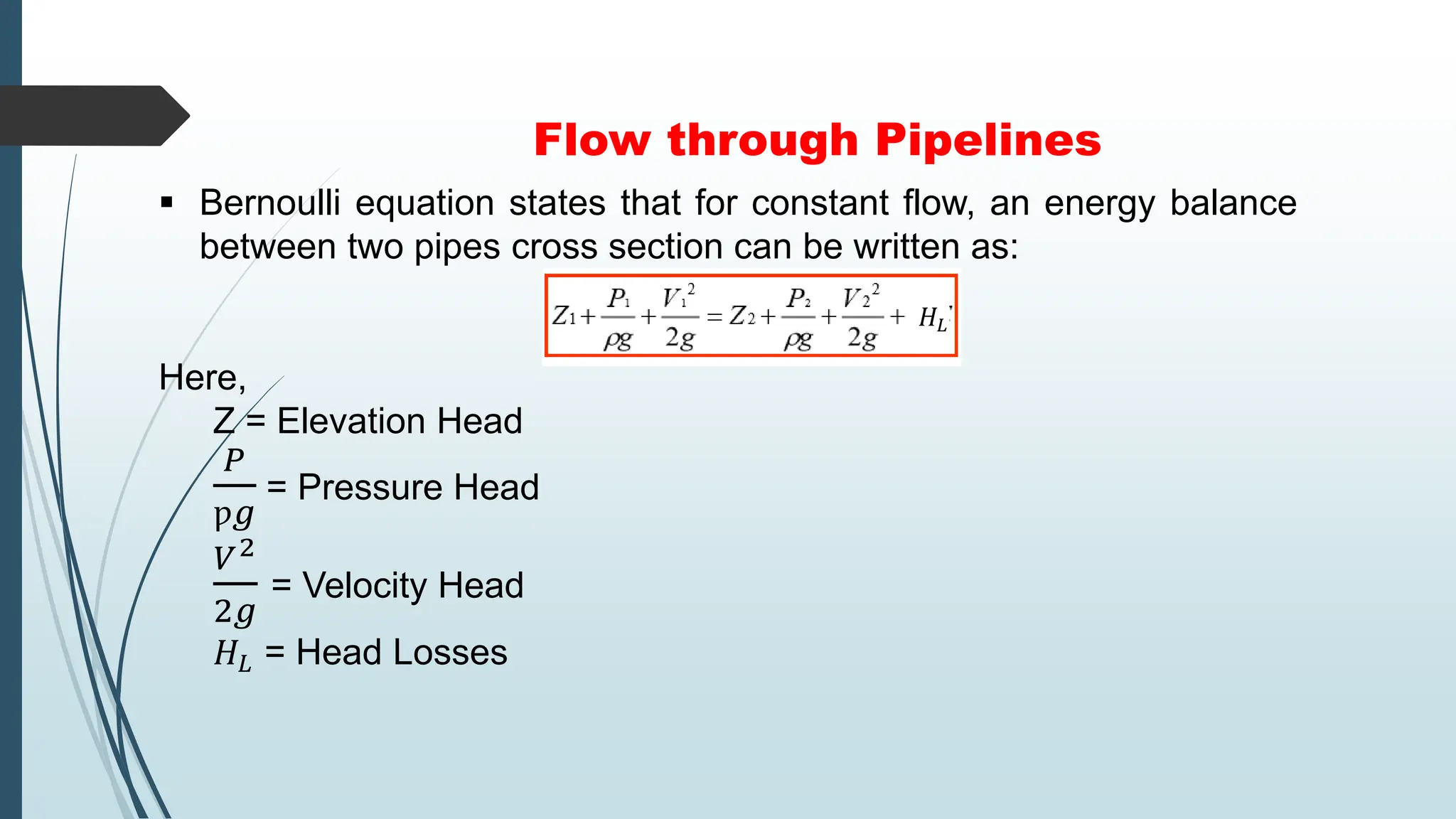
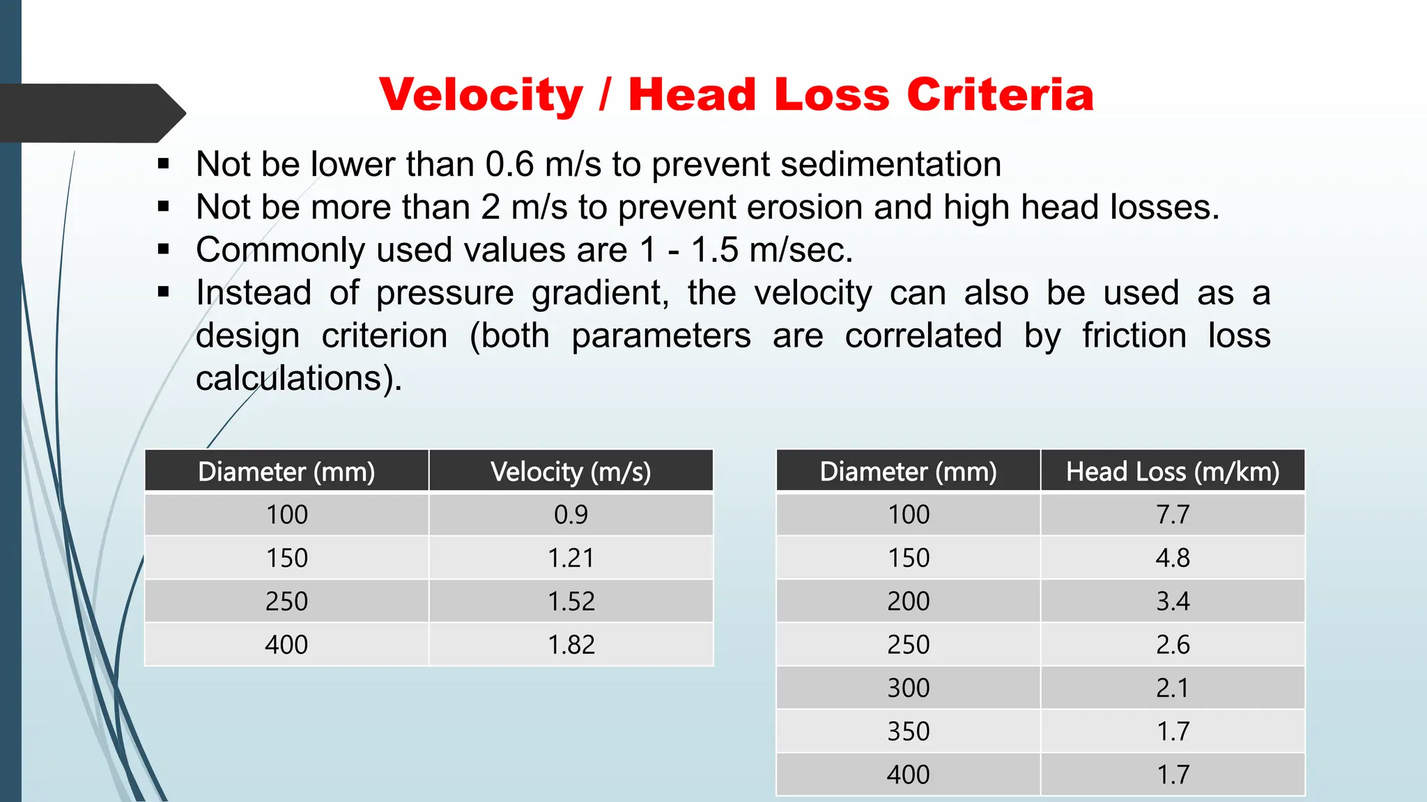
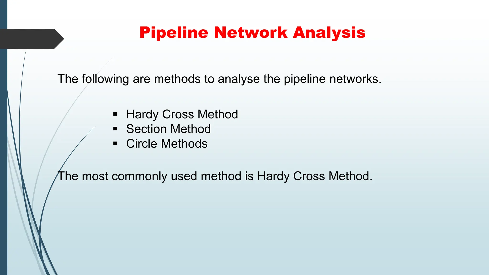
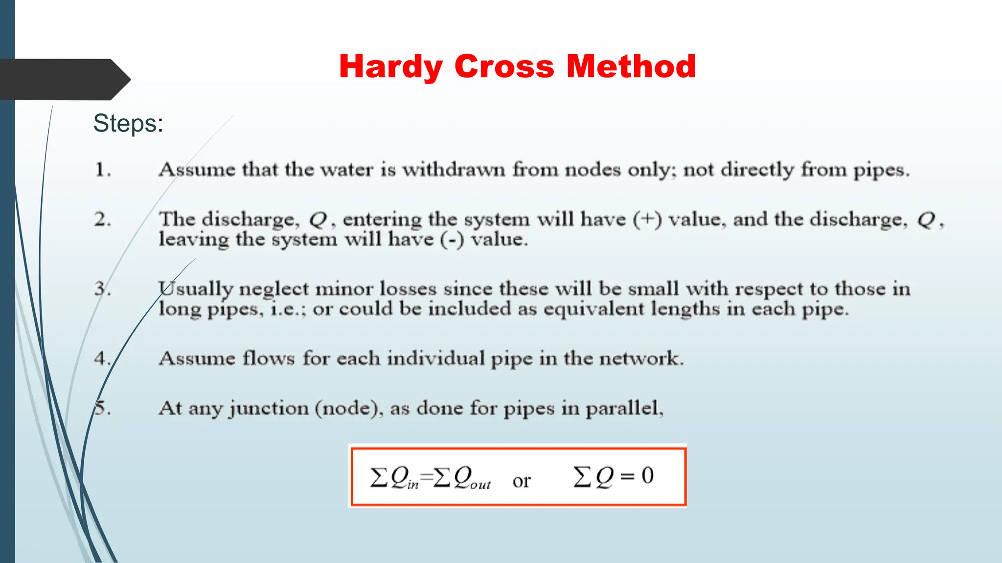
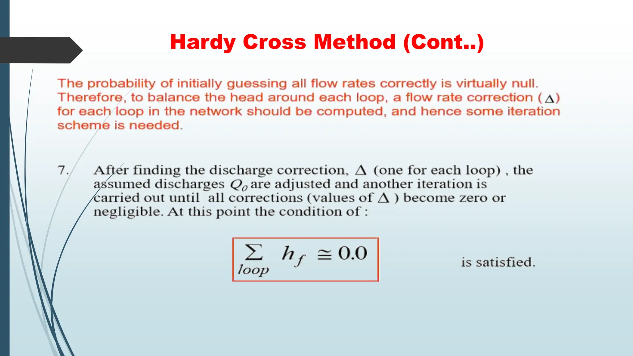
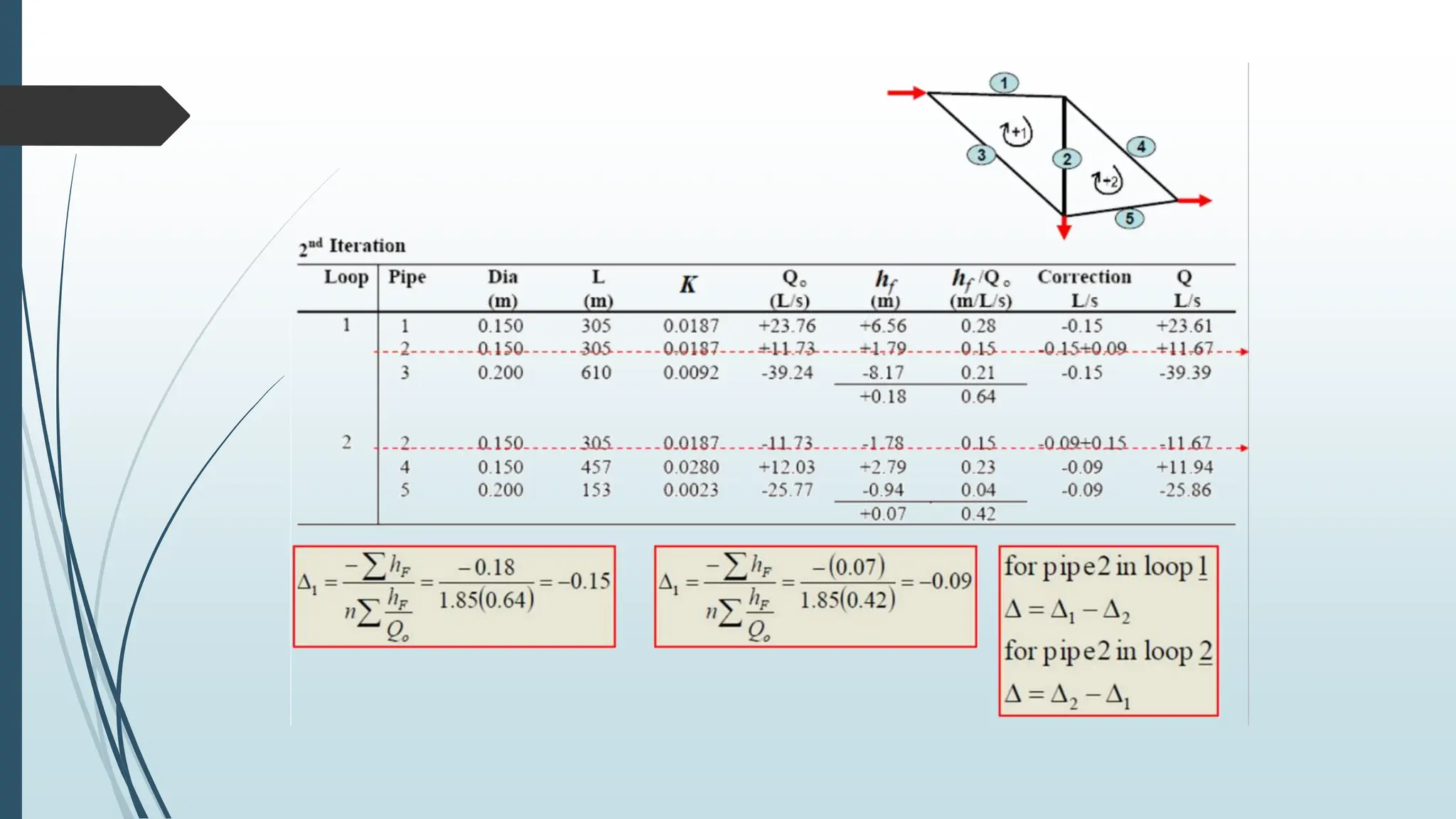
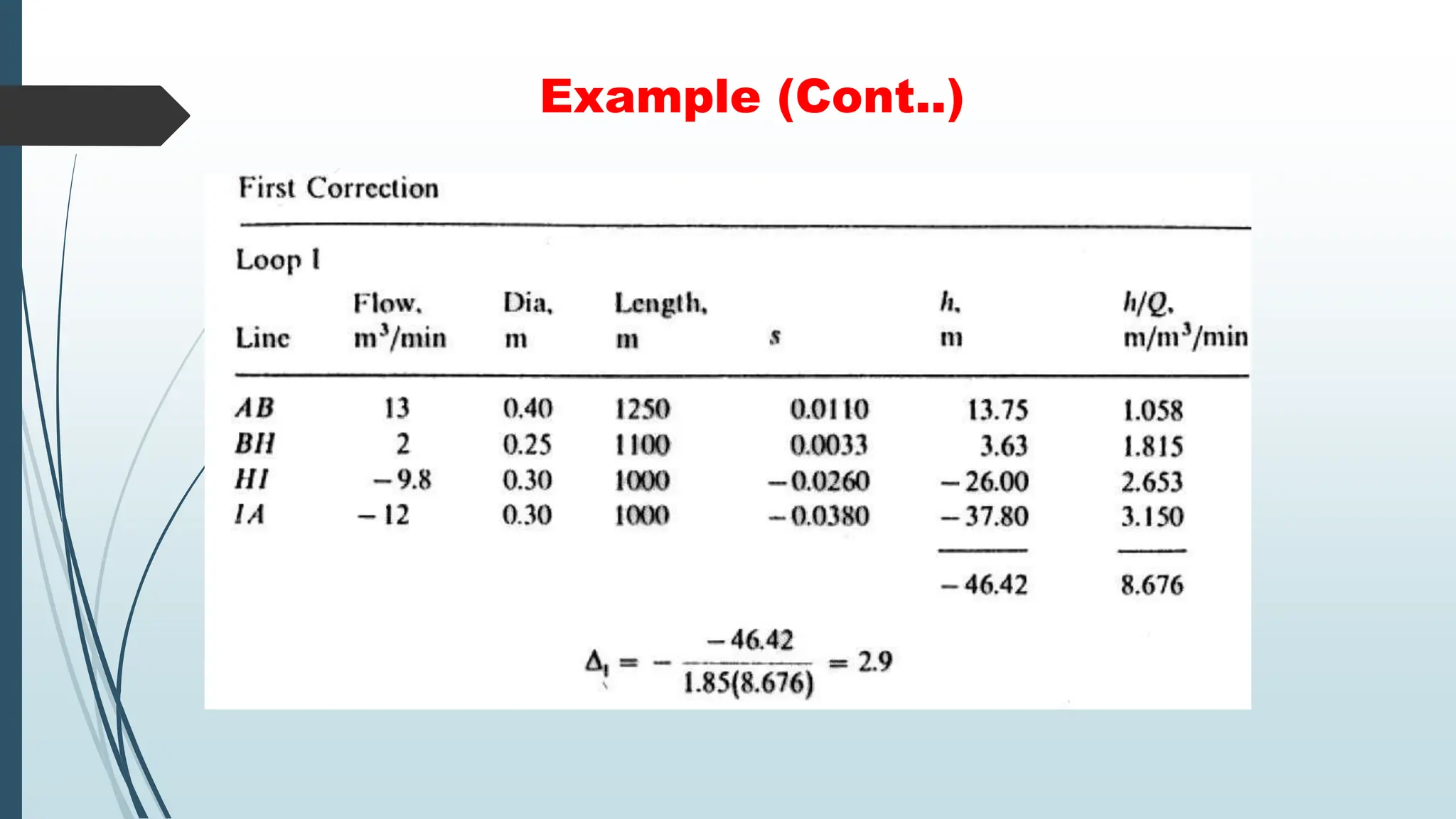
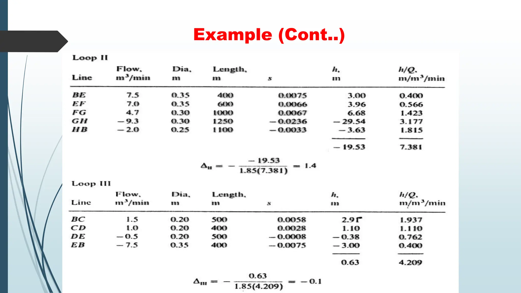
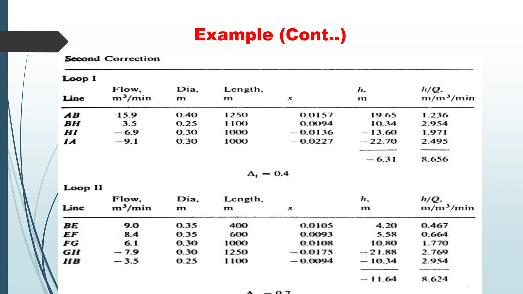
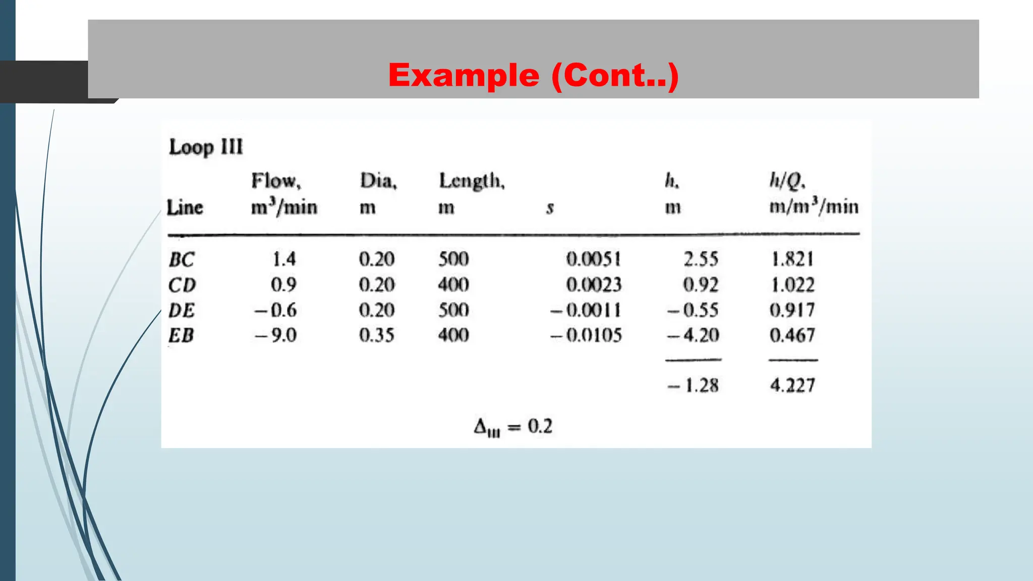
Pipeline Hydraulic Design
Pipe way Engineering
Department of Transportation Engineering and Management
University of Engineering and Technology Lahore
Lecture 6
Pipeline
Hydraulic
Design
Outline
 Flow through pipelines
 Flow through pipes in series
 Flow through parallel pipes
 Velocity/Head loss criteria
 Pipeline network analysis
 Hardy cross method
 General guideline for pipeline
networks
 Pipeline Materials
Pipeline Hydraulic Design
 Hydraulic design criteria are primarily related to the flow and
pressure in the network. Moreover, criteria for minimum and
maximum pipe capacities, flow velocities, pressure fluctuations
and pressure gradients are relevant factors.
 Detailed design of a complete pipeline system follows when the
results of economic planning show that the proposed project is
feasible.
 Pipe suitable for cross country transportation of fluids under
pressure is called line pipe to distinguish it from pipe suitable for
other purposes.
Flow through Pipelines
 Bernoulli equation states that for constant flow, an energy balance
between two pipes cross section can be written as:
Here,
Z = Elevation Head
𝑃
ƿ𝑔
= Pressure Head
𝑉2
2𝑔
= Velocity Head
𝐻𝐿 = Head Losses
𝐻𝐿
Flow through Pipelines
 Elevation Head: This is an amount of flow potential energy in one cross section defined
by the elevation.
 Pressure Head: This is an amount of the flow potential energy in one cross section
defined by the fluid pressure.
 Piezometric Head : this is the sum of elevation and pressure head in one cross section.
 Velocity Head : This is an amount of flow kinetic energy in one cross section defined by
the fluid velocity.
Flow through Pipes in Series
Discharge: The discharge through each pipe will be same.
Head loss: Total head loss will be the sum of the head loss in each pipe.
Flow through Parallel Pipes
Discharge: Total discharge will be the sum of discharge in each pipe.
Head loss: Total head loss will be same in each pipe.
Example
Four pipes are connected in parallel as shown. Using the following data
calculate the diameter of each pipe.
Pipe L (m) Q (𝒎𝟑/𝒔) f
1 200 0.0762 0.02
2 300 0.1146 0.018
3 150 0.28 0.015
4 100 0.1078 0.02
𝑍𝐴 = 150 m , 𝑍𝐵 = 144 m
Assume Pressure is same in
all pipes
Velocity / Head Loss Criteria
 Not be lower than 0.6 m/s to prevent sedimentation
 Not be more than 2 m/s to prevent erosion and high head losses.
 Commonly used values are 1 - 1.5 m/sec.
 Instead of pressure gradient, the velocity can also be used as a
design criterion (both parameters are correlated by friction loss
calculations).
Diameter (mm) Velocity (m/s)
100 0.9
150 1.21
250 1.52
400 1.82
Diameter (mm) Head Loss (m/km)
100 7.7
150 4.8
200 3.4
250 2.6
300 2.1
350 1.7
400 1.7
Pipeline Network Analysis
The following are methods to analyse the pipeline networks.
 Hardy Cross Method
 Section Method
 Circle Methods
The most commonly used method is Hardy Cross Method.
Hardy Cross Method
Steps:
Hardy Cross Method (Cont..)
Solve the following pipe network using Hazen William Method CHW =100
Example
Example
 The figure on the next slide represents a simplified pipe network.
 Flows for the area have been disaggregated to the nodes, and a major
fire flow has been added at node G.
 The fluid enters the system at node A.
 Pipe diameters and lengths are shown on the figure.
 Find the flow rate of fluid in each pipe using the Hazen Williams
equation with 𝐶𝐻𝑊 = 100.
 Carry out calculations until the corrections are less then 0.2 𝑚3/ min.
Example (Cont..)
Example (Cont..)
Example (Cont..)
Example (Cont..)
Example (Cont..)
Example (Cont..)
Example (Cont..)
Example (Cont..)
Example (Cont..)
General Guidelines for Pipeline Network
 Proper installation and operation of fluid flow system requires that a
number of appurtenances be provided in the pipeline.
 Pipes constructed of steel and other flexible material must have
valves that automatically allow air to enter when the pipeline is
empties in order to prevent a vacuum, which will cause the pipe to
collapse.
 The minimum cover under roadway should be 90cm and under paths
75cm.
 Pipes should follow the general contour of the ground.
General Guidelines for Pipeline Network
 Pipeline design requires that the size, strength and other properties of pipe need to
match the hydraulic requirements.
 Pipe lengths are sometimes limited by highway load restrictions, rough terrain, or
other factors.
 Purchasing and arranging for transportation and delivery of pipe to many points
along the route of the pipeline in time to fit construction schedules is accomplished
by the purchasing department working in close cooperation with engineering and
right of way departments.
 Other major material items are casing pipe for road crossings, gate valves and
other pipe fittings.
 Information and data collected during field surveys, corrosion surveys, preliminary
work by material purchasers are studied by design engineers for completing the
detailed project design.
Pipeline Materials
 There are two families of materials available for pipework systems: metallic and non-metallic
materials.
 Of these the most commonly used materials for piping are galvanized steel or iron, copper,
polybutylene, polyvinylchloride (PVC), chlorinated polyvinylchloride (CPVC) and
polyethylene (PE).
 Metal alloys, which far exceed the performance specifications of their respective parent
materials, are also widely used.
 Diesel oil pipelines are made from steel or plastic tubes which are usually buried. For Diesel
we do not use any galvanized pipe because zinc leaches into the fuel and cause injector
problems.
 Natural gas and heating fuel oil pipelines are constructed of carbon steel because carbon
steel is known for its durability and reliability. Because fuel oil as well as natural gas is non-
corrosive, there is no concern for scaling and corrosion on the inside of the pipe. However,
when installed outdoors, uncoated steel pipe can and will rust over time. So, minimum 12
inch soil cover is provided to the pipes or zinc coating is provided on pipelines.
References
 Cross, H. (November 1936), "Analysis of flow in networks of conduits or
conductors“, Engineering Experiment Station, Bulletin No. 286.
 "Water & Wastewater Engineering“, Retrieved April 11, 2011.
 Robert J. Houghtalen (2009), Fundamentals of Hydraulic Engineering
Systems, ISBN 9780136016380, Retrieved April 10, 2011.
 https://sciencing.com/prevent-rust-coatings-6469698.html
 http://www.opuspiping.org/pair.aspx?appID=-7928680137092577171&materialID=-
8141219041806519434
 https://www.carsondunlop.com/training/resources/everything-you-need-to-know-about-gas-
piping/

pipeline hydraulic design presentation.pptx

  • 1.
    Pipeline Hydraulic Design Pipeway Engineering Department of Transportation Engineering and Management University of Engineering and Technology Lahore Lecture 6
  • 2.
    Pipeline Hydraulic Design Outline  Flow throughpipelines  Flow through pipes in series  Flow through parallel pipes  Velocity/Head loss criteria  Pipeline network analysis  Hardy cross method  General guideline for pipeline networks  Pipeline Materials
  • 3.
    Pipeline Hydraulic Design Hydraulic design criteria are primarily related to the flow and pressure in the network. Moreover, criteria for minimum and maximum pipe capacities, flow velocities, pressure fluctuations and pressure gradients are relevant factors.  Detailed design of a complete pipeline system follows when the results of economic planning show that the proposed project is feasible.  Pipe suitable for cross country transportation of fluids under pressure is called line pipe to distinguish it from pipe suitable for other purposes.
  • 4.
    Flow through Pipelines Bernoulli equation states that for constant flow, an energy balance between two pipes cross section can be written as: Here, Z = Elevation Head 𝑃 ƿ𝑔 = Pressure Head 𝑉2 2𝑔 = Velocity Head 𝐻𝐿 = Head Losses 𝐻𝐿
  • 5.
    Flow through Pipelines Elevation Head: This is an amount of flow potential energy in one cross section defined by the elevation.  Pressure Head: This is an amount of the flow potential energy in one cross section defined by the fluid pressure.  Piezometric Head : this is the sum of elevation and pressure head in one cross section.  Velocity Head : This is an amount of flow kinetic energy in one cross section defined by the fluid velocity.
  • 6.
    Flow through Pipesin Series Discharge: The discharge through each pipe will be same. Head loss: Total head loss will be the sum of the head loss in each pipe.
  • 7.
    Flow through ParallelPipes Discharge: Total discharge will be the sum of discharge in each pipe. Head loss: Total head loss will be same in each pipe.
  • 8.
    Example Four pipes areconnected in parallel as shown. Using the following data calculate the diameter of each pipe. Pipe L (m) Q (𝒎𝟑/𝒔) f 1 200 0.0762 0.02 2 300 0.1146 0.018 3 150 0.28 0.015 4 100 0.1078 0.02 𝑍𝐴 = 150 m , 𝑍𝐵 = 144 m Assume Pressure is same in all pipes
  • 9.
    Velocity / HeadLoss Criteria  Not be lower than 0.6 m/s to prevent sedimentation  Not be more than 2 m/s to prevent erosion and high head losses.  Commonly used values are 1 - 1.5 m/sec.  Instead of pressure gradient, the velocity can also be used as a design criterion (both parameters are correlated by friction loss calculations). Diameter (mm) Velocity (m/s) 100 0.9 150 1.21 250 1.52 400 1.82 Diameter (mm) Head Loss (m/km) 100 7.7 150 4.8 200 3.4 250 2.6 300 2.1 350 1.7 400 1.7
  • 10.
    Pipeline Network Analysis Thefollowing are methods to analyse the pipeline networks.  Hardy Cross Method  Section Method  Circle Methods The most commonly used method is Hardy Cross Method.
  • 11.
  • 12.
  • 13.
  • 14.
  • 15.
  • 16.
    Solve the followingpipe network using Hazen William Method CHW =100 Example
  • 19.
    Example  The figureon the next slide represents a simplified pipe network.  Flows for the area have been disaggregated to the nodes, and a major fire flow has been added at node G.  The fluid enters the system at node A.  Pipe diameters and lengths are shown on the figure.  Find the flow rate of fluid in each pipe using the Hazen Williams equation with 𝐶𝐻𝑊 = 100.  Carry out calculations until the corrections are less then 0.2 𝑚3/ min.
  • 20.
  • 21.
  • 22.
  • 23.
  • 24.
  • 25.
  • 26.
  • 27.
  • 28.
  • 29.
    General Guidelines forPipeline Network  Proper installation and operation of fluid flow system requires that a number of appurtenances be provided in the pipeline.  Pipes constructed of steel and other flexible material must have valves that automatically allow air to enter when the pipeline is empties in order to prevent a vacuum, which will cause the pipe to collapse.  The minimum cover under roadway should be 90cm and under paths 75cm.  Pipes should follow the general contour of the ground.
  • 30.
    General Guidelines forPipeline Network  Pipeline design requires that the size, strength and other properties of pipe need to match the hydraulic requirements.  Pipe lengths are sometimes limited by highway load restrictions, rough terrain, or other factors.  Purchasing and arranging for transportation and delivery of pipe to many points along the route of the pipeline in time to fit construction schedules is accomplished by the purchasing department working in close cooperation with engineering and right of way departments.  Other major material items are casing pipe for road crossings, gate valves and other pipe fittings.  Information and data collected during field surveys, corrosion surveys, preliminary work by material purchasers are studied by design engineers for completing the detailed project design.
  • 31.
    Pipeline Materials  Thereare two families of materials available for pipework systems: metallic and non-metallic materials.  Of these the most commonly used materials for piping are galvanized steel or iron, copper, polybutylene, polyvinylchloride (PVC), chlorinated polyvinylchloride (CPVC) and polyethylene (PE).  Metal alloys, which far exceed the performance specifications of their respective parent materials, are also widely used.  Diesel oil pipelines are made from steel or plastic tubes which are usually buried. For Diesel we do not use any galvanized pipe because zinc leaches into the fuel and cause injector problems.  Natural gas and heating fuel oil pipelines are constructed of carbon steel because carbon steel is known for its durability and reliability. Because fuel oil as well as natural gas is non- corrosive, there is no concern for scaling and corrosion on the inside of the pipe. However, when installed outdoors, uncoated steel pipe can and will rust over time. So, minimum 12 inch soil cover is provided to the pipes or zinc coating is provided on pipelines.
  • 32.
    References  Cross, H.(November 1936), "Analysis of flow in networks of conduits or conductors“, Engineering Experiment Station, Bulletin No. 286.  "Water & Wastewater Engineering“, Retrieved April 11, 2011.  Robert J. Houghtalen (2009), Fundamentals of Hydraulic Engineering Systems, ISBN 9780136016380, Retrieved April 10, 2011.  https://sciencing.com/prevent-rust-coatings-6469698.html  http://www.opuspiping.org/pair.aspx?appID=-7928680137092577171&materialID=- 8141219041806519434  https://www.carsondunlop.com/training/resources/everything-you-need-to-know-about-gas- piping/