Download to read offline
![International Journal Of Microwave Engineering (JMICRO) Vol.1, No.4, October 2016
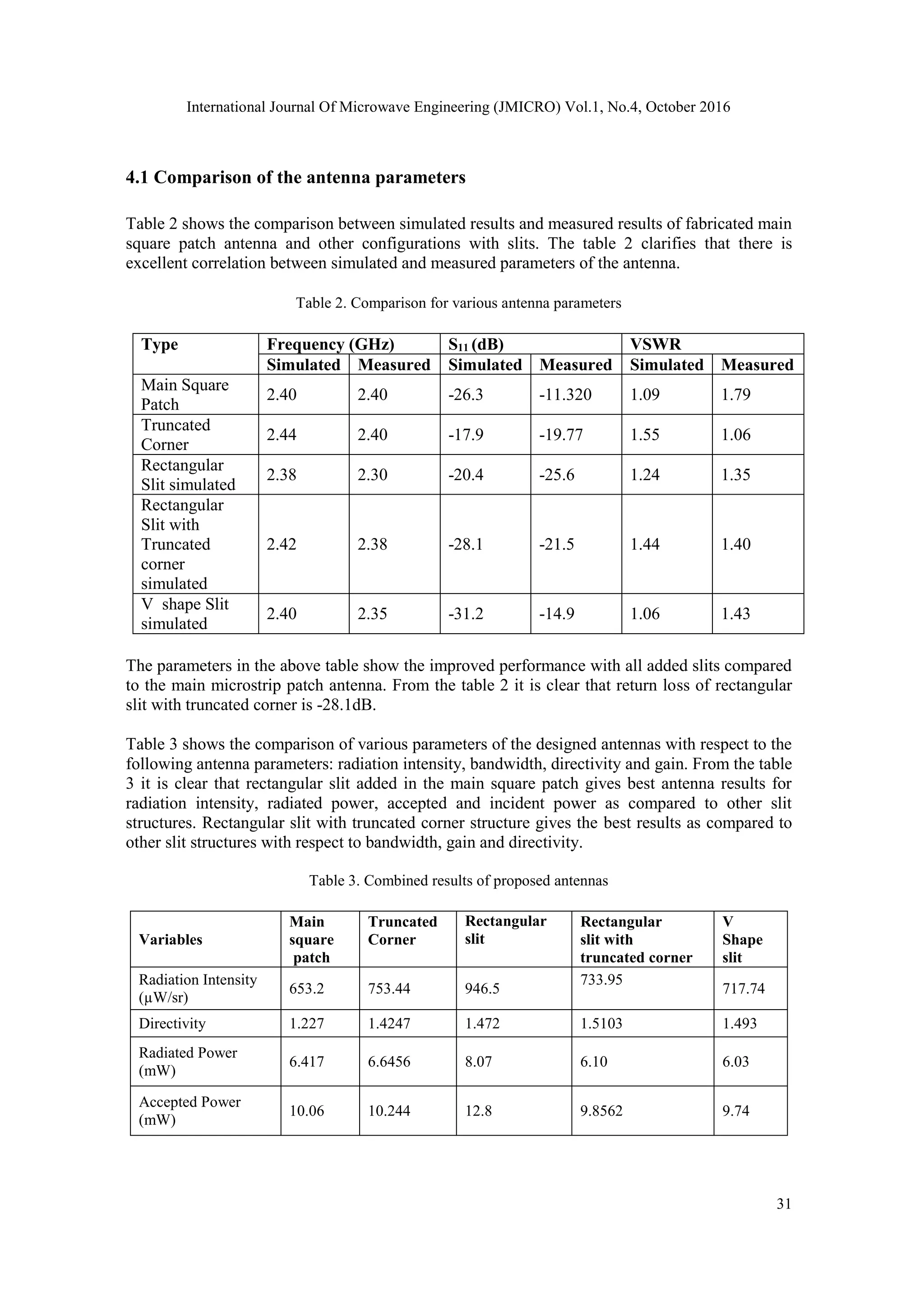
DOI:10.5121/Jmicro.2016.1403 23
EFFECT OF DIFFERENT SYMMETRIC SLITS ON
MICROSTRIP PATCH ANTENNA
Suvidya Pawar1
, R. Sreemathy2
and Shahadev Hake3
1
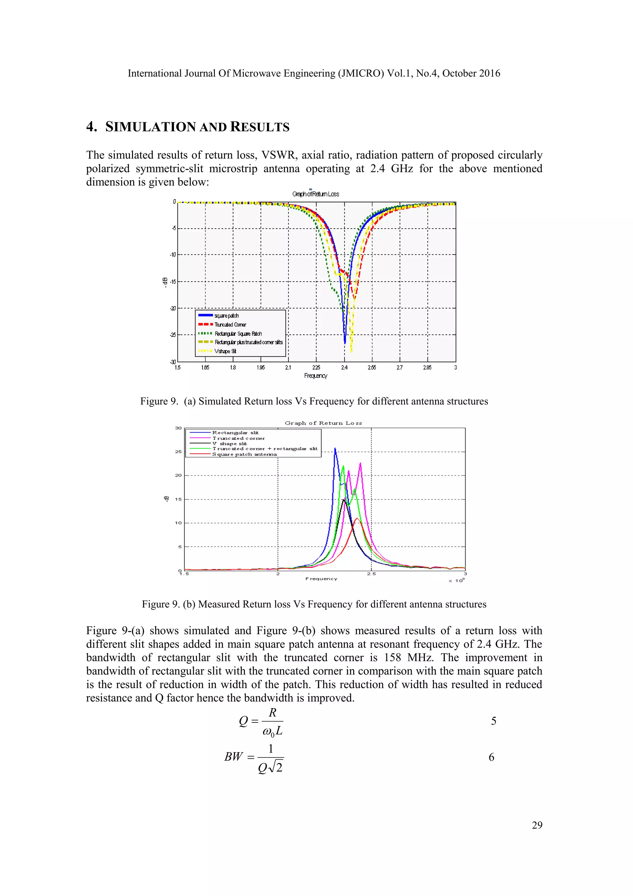
Department of Electronics and Telecommunication Engineering, Savitibai Phule Pune
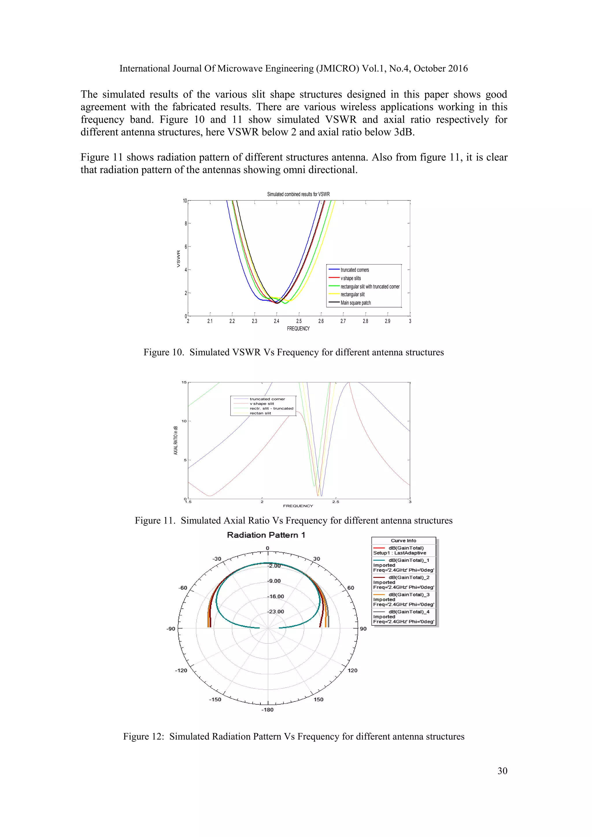
University, Pune, India
2
Associate Professor, Department of Electronics and Telecommunication Engineering,
Savitibai Phule Pune University, Pune, India
3
Assistant Professor, Department of Electronics and Telecommunication Engineering,
Savitibai Phule Pune University, Pune, India
ABSTRACT
In this paper, a basic linearly polarised microstrip square patch antenna operating at 2.4 GHz is
proposed. We have modified the basic microstrip square patch antenna with rectangular shape slits, V
shape slits and truncated corners to achieve circular polarization. Basically we have designed five
different antennas to meet the specification. The various antennas have been simulated, fabricated and the
performance has been tested on network analyser (Agilent Technologies: N9912A, SNMY51464189,
ROHDE & SCHWARZ: ZVL13, 9 KHz to 13.6GHz,). The simulated and tested performance shows close
agreement with each other. The various structures used in this study are microstrip square patch radiator,
microstrip square patch radiator with truncated corner, rectangular slits, truncated corner with
rectangular slits and V shape slits. The experiment results show rectangular slits with truncated corners in
the main square patch and rectangular slits in the main square patch provide better performance with
respect to the antenna parameters. Designed antenna is compact and provides circular polarization at the
required operating frequency of 2.4GHz with improved bandwidth and gain. The use of circularly
polarized antennas presents an attractive solution to achieve this polarization match which allows for
more flexibility in the angle between transmitting and receiving antennas. It gives the following
advantages such as reduction in the effect of multipath reflections, decrease in transmission losses,
enhancement of weather penetration and allowing any orientation to the communication system.
KEYWORDS
Wireless, microstrip antenna, circular polarization, slit.
1. INTRODUCTION
Communication technology and the relevant techniques are changing drastically these days.
Hence we require more sophisticated wireless communication equipment’s. The radio frequency
utilized by the system decides its range and the scalability [1, 2]. Different symmetric shaped
slotted microstrip patch antennas are proposed for circular polarization for radio frequency
identification applications [3]. Modern communication systems like cellular phones, personal
computer cards for wireless local area networks (WLAN) prefer microstrip antennas over other
radiators. These antennas provide advantages such as their light weight, low cost, low profile and
uncomplicated integration with circuit components of portable personal equipment’s.
Circularly polarized radiation can be generated with a symmetric slit on patch radiator having a
compact size [1, 4-7]. Compact circularly polarized microstrip antennas (CPMAs) are
fundamental requirement for applications such as cellular networks, radio-frequency](https://image.slidesharecdn.com/1416jmicro03-161105052233/75/EFFECT-OF-DIFFERENT-SYMMETRIC-SLITS-ON-MICROSTRIP-PATCH-ANTENNA-1-2048.jpg)
![International Journal Of Microwave Engineering (JMICRO) Vol.1, No.4, October 2016
24
identification (RFID) handheld readers, wireless LANs, receiver antennas for medical implants
and portable wireless devices because the overall antenna size is a major consideration for
such application [8-10]. Microstrip antennas are designed such that they have conducting patch
printed on a grounded microwave substrate giving attractive features of low profile and
conformability to mounting hosts.
CPMA using single feed technique does not require an external polarizer hence uses less board
space than dual feed CPMA giving advantages of simple structure and compactness. Various
reports in the literature have discussed many designs of single-feed, CPMAs with square or
circular patches having compact size at a fixed frequency of operation [9-14]. In these designs,
various compact CP techniques such as embedding a Y-shaped slot of unequal arm lengths,
truncating patch corners or tips, inserting slits or spur lines at the patch boundary, embedding a
cross slot of unequal arm lengths. These compact CP designs are fed by a probe feed or an edge-
fed microstrip line. Designs applied to a corner-truncated square microstrip antenna are presented
in detail [15, 16]. CP radiation of microstrip antenna operated at the TM11 mode has been
accomplished for the case of a pair of slits. [16-17].
2. STRUCTURE AND DESIGN
2.1. Specifications of the design
Square microstrip patch antenna is designed with following procedure [16, 17].
1
2
21
2
2
1 0
00
rrrr
f
v
f
W
(1)
5.0
121
2
1
2
1
w
hrr
reff
(2)
Where, 0v show the free-space velocity of light. Effective dielectric constant of the microstrip
antenna is determined using (2), Once W is calculated determine the extension of the length ∆L
using
8.0)258.0(
264.0)3.0(
412.0
h
W
h
W
hL
reff
reff
(3)
L
f
L
reffr
2
2
1
00
(4)
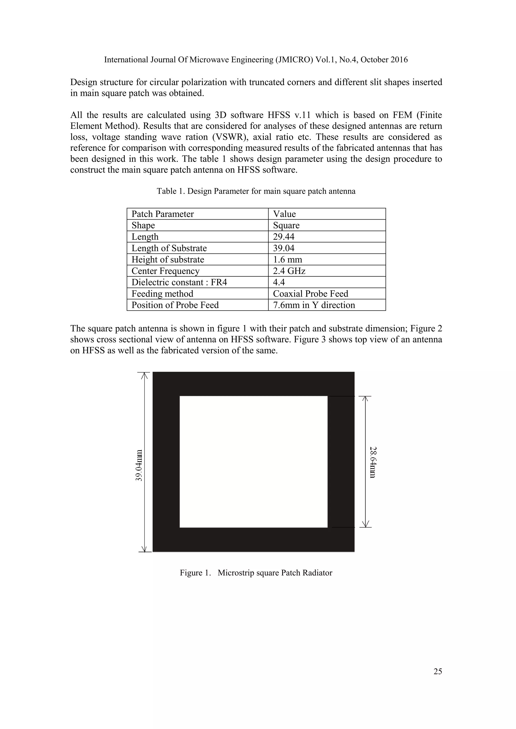
2.2. Design Parameter
By introducing a perturbation in the form of truncating two opposite edges and also adding slits
to a basic square patch antenna circular polarization is achieved. For square, elliptical and
circular microstrip patch antenna, the use of truncated edges and slits gives circular polarization.](https://image.slidesharecdn.com/1416jmicro03-161105052233/75/EFFECT-OF-DIFFERENT-SYMMETRIC-SLITS-ON-MICROSTRIP-PATCH-ANTENNA-2-2048.jpg)
![International Journal Of Microwave Engineering (JMICRO) Vol.1, No.4, October 2016
32
Incident Power
(mW)
10.06 10.079 12.98 10.21 9.75
Gain 0.815 0.924 0.928 0.935 0.925
Radiation Efficiency 63.76 67.87 63.08 61.959 61.95
Bandwidth (MHz) 90 150 140 158 116
5. CONCLUSIONS
In this work circular polarization has been achieved in all the configurations of added slits except
for the main square patch. The main square patch antenna provides a linear polarization. All the
measured parameters have shown an excellent improvement with respect to main square patch
antenna. The compactness in the structure has also been achieved. The rectangular slit with main
square patch and the rectangular slit with truncated corners give the best results with respect to
various parameters. When the rectangular slits are added to the main square patch the bandwidth
is improved by 55%. The bandwidth provided by rectangular slit with truncated corners is 75 %
more than that of the main square patch. The gain in the rectangular slit with truncated corner
antenna is also improved by 14 % compared to main square patch antenna.
The other parameters such as radiation intensity, radiated power, accepted and incident power are
improved in the rectangular slits added to the main square patch. Thus it can be concluded that
the addition of the rectangular slits and truncated corners have enhanced the performance of
main square patch antenna. Thus we have proposed highly efficient circularly polarized antennas
with modified slits added to the main square patch antenna which will be useful to the wireless
communication applications fulfilling the requirements of light weight, low cost, small size and
low power consumption along with better bandwidth.
REFERENCES
[1] P. M. Izdebski, H. Rajagopalan, and Yahya Rahmat-Samii, "Conformal Ingestible Capsule
Antenna: A Novel Chandelier Meandered Design," IEEE Transactions on Antennas and
Propagation, AP-57, 4, April 2009, pp. 900-9009.
[2] B. Hegyi and J. Levendovszky, "Enhancing the Performance of Medical Implant
Communication Systems through Cooperative Diversity," International Journal of
Telemedicine and Applications, 2010, 20 10 , Article ID 920704.
[3] S. D. Targonski and D. M. Pozar, "Design of Wideband Circularly Polarized Aperture-Coupled
Micro strip Antennas," IEEE Transactions on Antennas and Propagation AP-41, 2 February
1993, pp. 214- 219.
[4] P. C. Sharma and K. C. Gupta, "Analysis and Optimized Design of Single Feed Circularly
Polarized Microstrip Antennas," IEEE Transactions on Antennas and Propagation, AP-29, 6,
June 1983, pp. 949-955.
[5] S. M. Kim and W. G. Yang, "Single Feed Wideband Circular Polarized Patch Antenna,"
Electronics Letters, 43, 13, June 2007, pp .703-704.
[6] S. M. O’Kane and V. F. Fusco, "Printed Curl CP Antenna Design," IEEE Loughborough
Antennas and Propagation Conference, 2008, pp .109-1 12.
[7] C. Min and C. E. Free, "Analysis of Circularly Polarized Dual-Ring Microstrip Patch Array
Using Hybrid Feed," Microwaves, Antennas & Propagation, lET, 3, 3, March 2009.
[8] W. S. Chen, K. L. Wong, and C. K. Wu, "Inset Microstrip line-fed Circularly Polarized
Microstrip Antennas," IEEE Transactions on Antennas and Propagation, AP-48, 8, August
2000, pp. 1253- l254.](https://image.slidesharecdn.com/1416jmicro03-161105052233/75/EFFECT-OF-DIFFERENT-SYMMETRIC-SLITS-ON-MICROSTRIP-PATCH-ANTENNA-10-2048.jpg)
![International Journal Of Microwave Engineering (JMICRO) Vol.1, No.4, October 2016
33
[9] W. S. Chen, C. K. Wu, and K. L. Wong, "Novel Compact Circularly Polarized Square Microstrip
Antenna," IEEE Transactions on Antennas and Propagation, AP-49, 3, March 2001, pp. 340-
342.
[10] H. D. Chen, "Compact Circularly Microstrip Antenna with Slotted Ground Plane," Electronics
Letters, 38, 13, June 2002, pp .616-6 17.
[11] K. L. Wong and Y.F. Lin, "Circularly Polarized Microstrip Antenna with a Tuning Stub,”
Electronics Letters, 34, 9, April 1998, pp 831 -832.
[12] M. L. Wong, H. Wong, and K. M. Luk, "Small Circularly Polarized Patch Antenna," Electronics
Letters, 41, 16, August 2005, pp .7-8.
[13] K. L. Wong and J. Y. Wu, "Single-feed Small Circularly Polarized Square Microstrip Antenna,”
Electronics Letters, 33, 22, October 1997, pp.1833-1834.
[14] Nasimuddin, X. Qing, and Z. N. Chen, "Compact Circularly Polarized Microstrip Antenna for
RFID Handheld Reader Applications," Asia Pacific Microwave Conference, December 2009,
Singapore, pp. 1950-1953.
[15] R. Garg, P. Bhartia, I. Bahl, and A. Ittipiboon, Microstrip Antenna Design Hand book, Artech
House, Norwood, Mass, USA, 2001.
[16] Suvidya R. Pawar, R. Sreemathy, Shahadev D. Hake, “Design and fabrication of circularly
polarized microstrip antenna using symmetric ” International Journal of New Trends in
Electronics and Communication (IJNTEC—ISSN: 2347 - 7334) Vol. 2, Issue. 1, Jan. 2014
[17] Zhongbao Wang, Shaojun Fang, Qiang Wang, and Hongmei Liu, “An ANN-Based Synthesis
Model for the Single-Feed Circularly-Polarized Square Microstrip Antenna with Truncated
Corners”, IEEE Transactions on Antennas and Propagation, 2012
[18] Constantine A Balanis, “Antenna Theory: Analysis and Design” 3rd
edition, (April 4, 2005)
[19] Thomas A. Milligan “Modern antenna design” 2nd edition John Wiley and Son, Inc.2005.
[20] David M. Pozar “Microwave and RF design of wireless system” John Wiley and Son, Inc.2001.
Authors
Suvidya Pawar received his Bachelor of Engineering degrees in Electronics Engineering
from Shivaji University, in 2007 and the Master of Engineering degree in Electronics and
Telecommunication (Microwave) in 2013 from Pune University. He had ten months of
industrial experience. Since July 2008, he has been working with the Electronics and
Telecommunication Engineering Department, PICT, Pune.
Dr. R. Sreemathy is working as Associate Professor in E&TC Department of Pune
Institute of Computer Technology. She received her Post Graduate degree in Electronics
Engineering from COEP, Pune and her Doctoral degree from Shivaji University.She has
more than 25 years of teaching experience. She has more than 30 paper publications in
International conferences and Journals. Her areas of research include Signal Processing,
Artificial Intelligence and Wireless Communication.
Shahadev D. Hake received the Bachelor of Engineering degrees in Electronics and
Communication Engineering from Dr. BAMU, Aurangabad University, in 2009 and the
Master of Engineering degree in Electronics and Telecommunication in 2011 from Pune
University. Since December 2011, he has been working as Assistant Professor in the
Electronics and Telecommunication Engineering Department, PICT, Pune.](https://image.slidesharecdn.com/1416jmicro03-161105052233/75/EFFECT-OF-DIFFERENT-SYMMETRIC-SLITS-ON-MICROSTRIP-PATCH-ANTENNA-11-2048.jpg)

This paper presents a study on enhancing the performance of a microstrip patch antenna operating at 2.4 GHz by incorporating symmetric slits and truncated corners to achieve circular polarization. Five different antenna configurations were designed, simulated, fabricated, and tested, with results showing improved bandwidth and gain, particularly with rectangular slits and truncated corners. The findings suggest that these modifications significantly enhance the antenna's performance, making them suitable for various wireless communication applications.


