SlideShare a Scribd company logo
1
PROGRAMMABLE LOGIC CONTROL (PLC) BASED
AUTOMATIC POWER SOURCE CHANGE OVER
A PROJECT REPORT
Submitted by
R.S.GOKULNATH (912312105008)
M.KALAIVANI (912312105011)
A.M.MEENAKSHI (912312105017)
In partial fulfillment for the award of the degree
Of
BACHELOR OF ENGINEERING
IN
ELECTRICAL AND ELECTRONICS ENGINEERING
SACS MAVMM ENGINEERING COLLEGE,
KIDARIPATTI, MADURAI-625301.
ANNA UNIVERSITY :: CHENNAI 600 025
APRIL 2016
2
ANNA UNIVERSITY :: CHENNAI 600 025
BONAFIDE CERTIFICATE
Certified that this project report “PROGRAMMABLE LOGIC CONTROL
(PLC) BASED AUTOMATIC POWER SOURCE CHANGE OVER” is the
bonafide work of “R.S.GOKULNATH (912312105008), M.KALAIVANI
(912312105011), A.M.MEENAKSHI (912312105017)” who carried out the
project work under my supervision
SIGNATURE SIGNATURE
Prof. G.EMILY MANORANJITHAM, Mr.N.KEERTHIVARMAN,M.E
M.E(Ph.D).,M.I.S.T.E.,
HEAD OF THE DEPARTMENT SUPERVISOR
Electrical & Electronics Engineering Electrical & Electronics Engineering
SACS MAVMM ENGINEERING SACS MAVMM ENGINEERING
COLLEGE COLLEGE
Kidaripatti, Madurai-625301. Kidaripatti, Madurai-625301.
Submitted for the “Viva –Voce” Examination Held On: ………………………
INTERNAL EXAMINER EXTERNAL EXAMINER
3
ACKNOWLEDGEMENT
“THE FEAR OF THE LORD IS THE BEGINNING OF WISDOM”
It is the grace of GOD that has helped us to complete this project in a
successful manner. It is foremost for us to be grateful to him. May his mercy
endure forever
We would like to express our sincere thanks to our beloved Principle,
Dr.S.NAVANEETHA KRISHNAN for his immense help in completing our
project.
We would like to express profusely our deep sense of gratitude to our Head
of the Department Prof. G.EMILY MANORANJITHAM.,M.E.,M.I.S.T.E.,
(Ph.D)., and our guide Mr.N.KEERTHIVARMAN, M.E who have extended
their heartedly encouragement, advice and valuable guidance throughout the
project.
We also express our deep sense of gratitude to our staff
Prof.P.MUTHU,M.E for his valuable guidance in all activities and playing a
major role for successful completion of this project.
We also thanks all other Faculty Members and Supporting Staffs of
Electrical and Electronic Department for their support and encouragement. Above
all we express our heartedly respect to our parents.
4
ABSTRACT
The main objective of this project is to explain the uninterrupted power
supply to a load, by selecting the supply from different sources such as mains,
solar, inverter and generator automatically in the absence of any of the source. The
demand for electricity is increasing every day and frequent power cuts is causing
many problems in various areas like industries, hospitals and houses.
An alternative arrangement for power source is a must. This arrangement
can be designed by using PLC (Programming Logic Controller) and relays. When a
source, say mains fails the supply automatically shifts to next priority source solar.
When a source, say solar fails the supply automatically shifts to next priority
source generator and so on.
Use of PLC based automatic power source change over reduces the
operations time and reduces man power. Use of PLC results in faster operation and
accurate error detection thereby saving operating cost.
5
TABLE OF CONTENTS
CHAPTER NO TITLE PAGE NO
ABSTRACT IV
LIST OF FIGURES VII
LIST OF TABLES X
1 INTRODUCTION 1
1.1 PLC COMPARED WITH MICRO CONTOLLER 2
2 BLOCK DIAGRAM AND DESCRIPTION 6
2.1 BLOCK DIAGRAM 6
2.2 BLOCK DIAGRAM DESCRIPTION 6
3 HARDWARE DESCRIPTION 12
3.1 CIRCUIT DIAGRAM 12
3.2 CIRCUIT DIAGRAM DESCRIPTION 12
3.3. POTENTIAL TRANSFORMER CIRCUIT 14
3.4. OPERATIONAL AMPLIFIER 15
3.5. ULN DRIVER 20
6
3.6. TRANSISTOR AS A SWITCH 21
3.7 RELAY 22
3.8 VOLTAGE MEASUREMENT 24
3.9 VOLTAGE COMPARATOR 25
4 SOFTWARE DESCRIPTION 26
4.1. FUNDAMENTALS OF LOGIC 26
4.2. BASICS OF PLC PROGRAMMING 27
4.3. PLC PROGRAMMING LANGUAGE 29
4.4. TRUTH TABLE 35
4.5. LADDER DIAGRAM FOR SWITCH OVER 37
4.6. PLC LOGIC 38
5 PROGRAMMABLE LOGIC CONTROLLER (PLC) 39
5.1. HISTORY 39
5.2. DEVELOPMENT 40
5.3. TYPES OF PLC 41
5.4. STEPS FOR PLC OPERATION 42
5.5. PROGRAMMING 43
5.6. FUNCTIONALITY 44
5.7. PROGRAMMABLE LOGIC RELAY 45
7
5.8. SCAN TIME 46
5.9. SYSTEM SCALE 46
5.10. USER INTERFACE 47
5.11. COMMUNICATIONS 47
5.12. DISCRETE AND ANALOG SIGNALS 48
5.13. PLC HARDWARE COMPONENTS 49
6 APPLICATION AND FEATURES OF PLC 54
6.1. APPLICATION OF PLC 54
6.2. FEATURES OF PLC 55
7 ADVANTAGES AND FUTURE SCOPE OF PLC 57
8 RESULT 58
9 CONCLUSION 59
REFERENCE 60
8
LIST OF FIGURES
FIG NO TITLE PAGE NO
2.1 BLOCK DIAGRAM 6
3.1 CIRCUIT DIAGRAM 12
3.2.1 DUAL POWER CIRCIT 13
3.2.3 7812 +VE REGULATOR IC 14
3.2.4 7912 –VE REGULATOR IC 14
3.3 POTENTIAL TRANSFORMER 15
3.4.1 SYMBOLIC DIAGRAM OF OP AMP 16
3.4.2 INVERTING MODE 17
3.4.3 NON-INVERTING MODE 17
3.4.4 IC –741 PIN DIAGRAM 18
3.5.2 ULN 2003 PIN DIAGRAM 21
3.7.1 ELECTROMAGNETIC RELAY 23
3.7.1.1 ELECTROMAGNETIC RELAY CONTACT 23
3.7.2 RELAY DIVER 24
3.8 VOLTAGE MEASUREMENT 25
9
3.9 VOLTAGE COMPARATOR 25
4.1.1 LADDER DIAGRAM 26
4.2.1 LIFE CYCLE 28
4.3.1.1 SYMBOL DESCRIPTION 31
4.3.2 INSTRUCTION ADDRESS 32
4.3.3 BATCH INSTRUCTION 33
4.3.4 INTERNAL RELAY INSTRUCTION 34
4.4.1 LOGIC DIAGRAM FOR MAIN SOURCE 36
4.4.2 LOGIC DIAGRAM FOR SOLAR SOURCE 36
4.4.3 LOGIC DIAGRAM FOR GENERATOR 37
4.5 LADDER DIAGRAM FOR SWITCH OVER 37
4.6 SCREENSHOT OF PLC LOGIC 38
5.2 BLOCK DIAGRAM OF PLC 41
5.4 OPERATION CYCLE IN PLC 43
5.13.3.1 INPUT MODULE 50
5.13.4.1 OUTPUT MODULE 51
5.13.5 OUTPUT INTERFACING CIRCUIT 51
8.1 HARDWARE OF THE PROJECT 58
10
LIST OF TABLES
TABLE NO TITLE PAGE NO
1 MEMORY OF PLC 27
2 TRUTHTABLE 35
11
CHAPTER 1
INTRODUCTION
Now-a-days in industry life the energy management system is becoming
more expansion due to complex in every unit. Mainly cement, steel and paper
processing unit expansion and updating of machines. The objective of Energy
Management is to achieve and sustained optimum energy utilization throughout the
organization to reduce the energy costs or waste without affecting production and
quality and to minimize the environmental effects. Energy saving is important and
effective at all levels of human organizations in the whole world. Energy
Conservation reduces the energy costs and improves the effectiveness.
An important requirement of electric power distribution systems is the need
for automatic operation. In particular, the rapid and reliable transfer of the system
from one power source to another during certain system events is important in
achieving the reliability goals for such systems and the facility serves. However,
the design of such an automatic transfer system is all–too-often considered “less
important” then many other aspects of the overall power system design.
In existing method, maintaining of auto change over is the toughest job. The
knobs in auto change over gets weaker often, so maintain cost gets high, due to this
power source breakdown makes the whole process often get shutdown. In our
proposed method, the auto changeover is to replace through a latest idea of a load
based auto switching methods. Due to this technique each power source will be
supply to an individual station according to it power consumption.
12
This paper deals with the three sources used to give continuous power supply
to the load without interruption. Here voltage is used as a measuring parameter.
The measured voltage is compared with the actual set voltage in the comparator.
The output of the comparator is given as input signal of the PLC. A PLC of
Siemens 7300 is used. If the comparator output is positive means PLC considered
the input as HIGH otherwise LOW. The program for PLC written by using ladder
logic. The output of plc is given to the relay driver IC, which switches appropriate
relay to maintain uninterrupted supply to the load. The output shall be observed
using a lamp drawing power supply from mains initially. On failure of the mains
supply the load gets supply from the next available sources are solar, generator. If
the solar also fails it switches over to the next available source and so on. Three
LEDS are used to indicate what are the source are available to give the power
supply to the load.
1.1. PLC COMPARED WITH MICROCONTROLLER SYSTEM
PLCs are well adapted to a range of automation tasks. These are typically
industrial processes in manufacturing where the cost of developing and
maintaining the automation system is high relative to the total cost of the
automation, and where changes to the system would be expected during its
operational life. PLCs contain input and output devices compatible with industrial
pilot devices and controls; little electrical design is required, and the design
problem centers on expressing the desired sequence of operations. PLC
applications are typically highly customized systems, so the cost of a packaged
PLC is low compared to the cost of a specific custom-built controller design. On
the other hand, in the case of mass-produced goods, customized control systems
are economical. This is due to the lower cost of the components, which can be
13
optimally chosen instead of a "generic" solution, and where the non-recurring
engineering charges are spread over thousands or millions of units.
For high volume or very simple fixed automation tasks, different techniques
are used. For example, a consumer dishwasher would be controlled by an
electromechanical cam timer costing only a few dollars in production quantities.
A microcontroller-based design would be appropriate where hundreds or
thousands of units will be produced and so the development cost (design of power
supplies, input/output hardware, and necessary testing and certification) can be
spread over many sales, and where the end-user would not need to alter the control.
Automotive applications are an example; millions of units are built each year, and
very few end-users alter the programming of these controllers. However, some
specialty vehicles such as transit buses economically use PLCs instead of custom-
designed controls, because the volumes are low and the development cost would be
uneconomical.
Very complex process control, such as used in the chemical industry, may
require algorithms and performance beyond the capability of even high-
performance PLCs. Very high-speed or precision controls may also require
customized solutions; for example, aircraft flight controls. Single-board
computers using semi-customized or fully proprietary hardware may be chosen for
very demanding control applications where the high development and maintenance
cost can be supported. "Soft PLCs" running on desktop-type computers can
14
interface with industrial I/O hardware while executing programs within a version
of commercial operating systems adapted for process control needs.
Programmable controllers are widely used in motion, positioning, and/or
torque control. Some manufacturers produce motion control units to be integrated
with PLC so that G-code (involving a CNC machine) can be used to instruct
machine movements.
PLCs may include logic for single-variable feedback analog control loop,
a proportional, integral, derivative (PID) controller. A PID loop could be used to
control the temperature of a manufacturing process, for example. Historically
PLCs were usually configured with only a few analog control loops; where
processes required hundreds or thousands of loops, a distributed control
system (DCS) would instead be used. As PLCs have become more powerful, the
boundary between DCS and PLC applications has been blurred.
PLCs have similar functionality as remote terminal units. An RTU, however,
usually does not support control algorithms or control loops. As hardware rapidly
becomes more powerful and cheaper, RTUs, PLCs, and DCSs are increasingly
beginning to overlap in responsibilities, and many vendors sell RTUs with PLC-
like features, and vice versa. The industry has standardized on the IEC 61131-
3 functional block language for creating programs to run on RTUs and PLCs,
although nearly all vendors also offer proprietary alternatives and associated
development environments.
15
In recent years "safety" PLCs have started to become popular, either as
standalone models or as functionality and safety-rated hardware added to existing
controller architectures (Allen-Bradley Guardlogix, Siemens F-series etc.). These
differ from conventional PLC types as being suitable for use in safety-critical
applications for which PLCs have traditionally been supplemented with hard-
wired safety relays. For example, a safety PLC might be used to control access to a
robot cell with trapped-key access, or perhaps to manage the shutdown response to
an emergency stop on a conveyor production line. Such PLCs typically have a
restricted regular instruction set augmented with safety-specific instructions
designed to interface with emergency stops, light screens, and so forth. The
flexibility that such systems offer has resulted in rapid growth of demand for these
controllers.
16
CHAPTER 2
BLOCK DIAGRAM AND DESCRIPTION
2.1. BLOCK DIAGRAM
Fig 2.1 Block Diagram
2.2. BLOCK DIAGRAM DESCRIPTION
2.2.1. MAIN AND GENSET MEASUREMENT
In this, voltage protection circuit is used to sense the voltage in between the
phase and neutral in 3 phase 4 wire system.
Here 230V supply given to the input of the primary winding of the potential
transformer. The potential transformer is step - down the voltage in (6-0-6V).
P.T
I2
GENSET
IN
P.T
I1
SOLAR
PANEL
-
LOAD BUS
+
-
+
-
LOAD
BUS
RECTIFIER
WITH
FILTER
BATTERY
GENSET
IN
RELAY
COMPARATOR
SOLAR
IN
COMPARATOR
RELAY
MAINS
IN
+
-
+
MAINS
IN
+
RELAY
-
+
RELAY
C
POTENTIAL
DIVIDER
RELAY
L
+
- RELAY
P
-
-
Q1
+
Q2
RECTIFIER
WITH
FILTER
I3
COMPARATOR
Q3
17
The stepped down AC 6-0-6V is rectified and filtered by using of this full
wave rectifier and filtering circuits. At this smooth dc low voltage applied across
the variable resistor 10K which is used to provide the variable dc milli voltage.
This voltage is fed to the comparator.
2.2.2. SOLAR PHOTOVOLTAIC ARRAY
The solar photovoltaic array consists of an appropriate number of solar cells
connected in series and or parallel to provide the required current and voltage. The
array is so oriented as to collect the maximum solar radiation throughout the year.
There may be tracking arrays or modules or fixed arrays. A tracking array is
defined as one which is always kept mechanically perpendicular to the sun array
line so that all times it intercepts the maximum isolation. Such arrays must be
physically movable by a suitable prime mover and are generally considerably more
complex than fixed arrays. A fixed array is usually oriented east west and tilted up
at an angle approximately equal to the latitude of the site. Thus the array design
falls into two broad classes:
(I) FLAT PLATE ARRAYS
Where in solar cells are attached with a suitable adhesive to some kind of
substrate structure usually semi rigid to prevent cells being cracked.
18
This technology springs from the space related photovoltaic technology and
many such arrays have been built in various power sizes.
(II) CONCENTRATING ARRAYS
Wherein suitable optics, e.g. Fresnel lenses, parabolic mirrors are combined
with photovoltaic cells in an array fashion. This technology is relatively new to
photovoltaic in terms of hardware development and comparatively fewer such
arrays have actually been built.
2.2.3. BATTERY BANK
In most alone PV power systems, storage batteries with charge regulators
have to be incorporated to provide a backup power source during periods of low
solar irradiance and night. Several types of accumulator are available in the market
for use in PV power systems. The main requirements to be met by an accumulator
for solar power system are,
 Ability to withstand several charge/discharge cycle.
 A low self discharge rate
 Little or no need for maintenance
The capacity of a battery is the total amount of electricity that can be drawn
from a fully charged battery at a fixed discharge rate and electrolyte temperature
until the voltage falls to a specified minimum. It is expressed in ampere hour. The
capacity of the battery also depends upon the temperature and age of battery.
19
The batteries in most PV systems are of lead acid type consisting of one or
more 2v cells. Each cell has a positive plate of lead peroxide and a negative plate
of sponge lead. The electrolyte is dilute sulphuric acid. During discharging when
current is drawn from it, the material of both plates’ changes to lead sulphate and
water content in the electrolyte increases thereby reducing its specific gravity.
When the battery is charged by passing electric current through it in the
opposite direction, the reverse chemical reaction takes place. The cell voltages are
typically 2.4v and 1.9v for fully charged and deeply discharged battery
respectively. Lead acid batteries self discharge slowly when not in use.
2.2.4. PROGRAMMING LOGIC CONTROLLER
The signals from the fault detecting circuits will be connected to the PLC
controller. Here are using Siemens PLC. Here we are using SIEMENS make
LOGO model P.L.C., which is having 8 inputs and 4 outputs.
2.2.5. DRIVER CIRCUIT
The relay section contains relays and ULN2003driver. The microcontroller
gives a logic high output when required and this logic high output has to drive the
relay. The ULN2003 is comprised of seven high voltage, high current NPN
Darlington transistor pairs. All units feature common emitter, open collector
outputs. To maximize their effectiveness, these units contain suppression diodes
20
for inductive loads and appropriate emitter base resistors for leakage. The
ULN2003 has a series base resistor to each Darlington pair, thus allowing
operation directly with TTL or CMOS operating at supply voltages of 5.0V.
The ULN2003 offers solutions to a great many interface needs, including
solenoids, relays, lamps, small motors, and LEDs. Applications requiring sink
currents beyond the capability of a single output may be accommodated by
paralleling the outputs.
2.2.6. RELAY
Relays are switching devices. Switching devices are the heart of
industrial electronic systems. When a relay is energized or activated,
contacts are made or broken. They are used to control ac or dc power.
Electromagnetic relays are forms of electromagnets in which the coil
current produces a magnetic effect. It pulls or pushes flat soft iron
armatures or strips carrying relay contacts. Several relay contact can be
operated to get several possible ON/OFF combinations.
2.2.7. POWER SUPPLY
A power supply circuit is very essential in any project. This power supply
circuit is designed to get regulated output DC voltage. The 15-0-15 volt
transformer, step down the main voltage (230v) into15 volts. The secondary
voltage of transformer is rectified using bridge rectifier. The rectified
unidirectional DC is smoothed by 1000mf filter capacitor. The smooth DC is then
21
fed to the three terminal +ve regulator called 7812 to get 12v DC supply. -ve
regulator called 7912 to get -12v DC supply. The power supply section is for
supplying voltages to the entire circuit.
22
CHAPTER 3
3. HARDWARE DESCRIPTION
3.1. CIRCUIT DIAGRAM
Fig 3.1Circuit diagram
3.2. CIRCUIT DIAGRAM DESCRIPTION
3.2.1. DUAL POWER SUPPLY
It is an electronics unit. This is used to give regulated power to any
electronics system.
23
Fig 3.2.1 Dual power supply
3.2.2. CIRCUIT DESCRIPTION
This power supply circuit is designed to get regulated output dc voltage. The
9 volt transformer, step down the main voltage (230v) into 9 volts. The secondary
voltage of transformer is rectified using bridge rectifier. The rectified
unidirectional dc is smoothed by 1000mf filter capacitor. The smooth dc is then fed
to the three terminal +ve regulator called 7805 to get 5v dc supply.
3.2.3. CIRCUIT OPERATIONS
The mains voltage ac 230v is step down to 9 volt, using 9v step down
transformer. The low value secondary voltage is fed to the rectifier is formed using
four no. of IN4007. For first half cycle, diodes d1 & d2 come to action and next
7812
1
2
3
7912
IN4007*4
0.1MF
+
1000MF/25V
0-230V AC
STEP DOWN TRANSFORMER
15V
GREEN
+
100MF/25V
+12V
GND
3
2K2
2
1
0V
15V
+
100MF/25V
REDPH
0.1MF
+
1000MF/25V
NE
-12V
2K2
24
half cycle diode d3 & d4 come to action, finally unidirectional dc supply is fed to
the filter capacitor. The charging & discharging property of capacitor provide pure
smooth dc is nearly peak value of the secondary voltage. The pure dc supply is fed
to regulator IC’s input terminal. Due to the regulator action, finally, regulated 5
volts is available at output terminals.
Fig 3.2.3 7812 Regulator IC pin
Fig 3.2.4 7912 Regulator IC pin
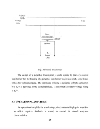
3.3. POTENTIAL TRANSFORMER CIRCUIT
Potential transformers are used to operate voltmeters, the potential coils of
watt meters and relays from high voltage lines. The primary winding of the
transformer is connected across the line carrying the voltage to be measured and
the voltage circuit is connected across the secondary winding.
25
Fig 3.3 Potential Transformer
The design of a potential transformer is quite similar to that of a power
transformer but the loading of a potential transformer is always small, some times
only a few voltage ampere. The secondary winding is designed so that a voltage of
9 to 12V is delivered to the instrument load. The normal secondary voltage rating
is 12V.
3.4. OPERATIONAL AMPLIFIER
An operational amplifier is a multistage, direct-coupled high-gain amplifier
to which negative feedback is added, to control its overall response
characteristics.
26
Now Op-amp is used for a variety of applications, such as DC and AC signal
amplification, oscillators, comparators, voltage regulators and many others.
3.4.1. SYMBOLIC DIAGRAM OF OPERATIONAL AMPLIFIER
Figure shows the block diagram of a typical op-amp. There are two inputs,
labeled as V1 and V2. The input voltage is V1 and V2 with respect to the ground.
The output voltage is Vo with respect to ground. The output is given by,
Fig 3.4.1 Symbolic diagram of operational amplifier
3.4.2. INVERTING MODE
Where AV is the voltage gain of the op-amp. AV is assumed to be negative
for the differential input V1-V2. It is seen that Vo is proportional to negative of V1.
27
Hence, a signal applied as V1 is inverted (180o
phase change) at the output. So V1
is called the inverting input. It is denoted by a negative sign at the terminal in the
block diagram.
Fig 3.4.2 Inverting mode
3.4.3. NON-INVERTING MODE
Any signal applied as the other input voltage V2 produce an output
proportional to V2 and is in phase with it. Hence V2 is called the Non-inverting
input. It is denoted by ‘plus’ sign at the terminal in the block diagram.
Fig 3.4.3 Non-inverting mode
There is one lead common to both the inputs and the output. This is the
ground lead. Since the ground lead is common to all parts of the circuit, it is often
not shown in diagrams. For using the op-amp, it must be connected to a dual
power supply (having +Vcc and –Vcc with respect to common earth).
28
The function of the op-amp described above can be summarized as follows:
If differential input Vid = (V1 – V2) is positive; the output is negative (VO).
If differential input Vid = (V1 – V2) is negative; the output is positive (+VO).
3.4.4. IC-741 PIN DETAILS
Fig 3.4.4 IC-741 pin diagram
The op-amp symbol is a triangle that points in the direction of the signal flow.
This component has a Part Identification Number (PIN) placed within the
triangular symbol. Of the different types of op-amps produced, op-amp IC 741
type is widely used. It is available in 8 pin Dual-In-Line Package (DIP) or in TO-
style package. The pin configuration of the 8 pin (DIP) package is shown in
figure.
29
The operational amplifier needs a dual symmetrical power supply (+Vcc and –
Vcc) with the center tap of the power transformer secondary earthed. This earth is
used as the common earth for all voltage sources in the circuit.
The important technical parameters of IC 741 are given below:
Supply voltage :  5 to  18V
Input resistance : Zin = 2 Mega ohms
Output resistance : Zo = 75 ohms
Voltage gain : Av = 200,000 (106 dB)
Small signal band width : 1 Megahertz
Power consumption : 50-85 mW
Output short-circuit current : 25mA
Slew rate : 0.5 V/ s
3.4.5. ADVANTAGES OF OPERATIONAL AMPLIFIER
For a given operation, OP-Amps have the following advantages over
conventional amplifier.
 Smaller size
 Higher reliability of operation
 Reduced cost
 Low offset voltage and current
30
 High versatility
 More flexibility
3.5. ULN DRIVER
3.5.1. HIGH CURRENT/VOLTAGE DARLINGTON DRIVERS
The ULN2003 is comprised of seven high voltage, high current NPN
Darlington transistor pairs. All units feature common emitter, open collector
outputs. To maximize their effectiveness, these units contain suppression diodes
for inductive loads and appropriate emitter base resistors for leakage. The
ULN2003 has a series base resistor to each Darlington pair, thus allowing
operation directly with TTL or CMOS operating at supply voltages of 5.0V.
The ULN2003 offers solutions to a great many interface needs, including
solenoids, relays, lamps, small motors, and LEDs. Applications requiring sink
currents beyond the capability of a single output may be accommodated by
paralleling the outputs.
31
3.5.2. ULN 2003 PIN DIAGRAM
Fig 3.5.2 ULN 2003 pin diagram
3.5.3. FEATURES OF ULN DRIVER
 Seven high gain Darlington pairs
 High output voltage (VCE = 50V)
 High output current (IC = 350 mA)
 TTL, PMOS, CMOS compatible
 Suppression diodes for inductive loads
 Extended temperature range
3.6. TRANSISTOR AS A SWITCH
When a transistor is used as driver circuit, it can withstand for high
frequency signal. So a NPN transistor is used here as a driver circuit. When
32
a transistor is used as a switch it is usually required to be brought
alternatively in the saturation and in the cut-off conditions.
When in saturation condition, it should carry heavy current so that the
voltage drop across it is as near to zero as possible and when in cutoff
condition, it should carry almost no current so that it may be considered to
be an open switch. It is found that the transistor does not respond
instantaneously but takes a certain definite, though quite small, time in
making a transition from one state to the other.
3.7. RELAY
Relays are switching devices. Switching devices are the heart of
industrial electronic systems. When a relay is energized or activated,
contacts are made or broken. They are used to control ac or dc power. They
are used to control the sequence of events in the operation of a system such
as an electronic heater, counter, welding circuits, X-ray equipment,
measuring systems, alarm systems and telephony. Electromagnetic relays
are forms of electromagnets in which the coil current produces a magnetic
effect. It pulls or pushes flat soft iron armatures or strips carrying relay
contacts. Several relay contact can be operated to get several possible
ON/OFF combinations.
33
3.7.1. OPERATION OF ELECTROMAGNETIC RELAY
Relays are usually dc operated. When dc is passed to the coil, the
core gets magnetized. The iron armature towards the core contacts 1 and 2
open and contacts 2 and 3 close. When coil current is stopped, the
attraction is not there and hence the spring tension brings 1 and 2 to closed
position, opening the other set 2 and 3.
Fig 3.7.1 operation of electromagnetic relay
Fig 3.7.1.1 Contact of electromagnetic relay
34
3.7.2. RELAY DRIVER CIRCUIT
Fig 3.7.2 Relay diver circuit
3.8. VOLTAGE MEASUREMENT
In this, voltage protection circuit is used to sense the voltage in between the
phase and neutral in 3 phase 4 wire system.
Here 230V supply given to the input of the primary winding of the potential
transformer. The potential transformer is step - down the voltage in (6-0-6V).
The stepped down AC 6-0-6V is rectified and filtered by using of this full
wave rectifier and filtering circuits. At this smooth dc low voltage applied across
the variable resistor 10K which is used to provide the variable dc milli voltage.
This voltage is fed to the comparator.
35
Fig 3.8 Voltage measurement circuit
3.9. VOLTAGE COMPARATOR
The input from the voltage measurement is given to inverting terminal and
the set value of voltage is given to non-inverting terminal. This can be set by using
the variable resistance 10K. At normal 230v, the voltage at the inverting terminal
is more than reference, so –V sat is the output from op amp. When the voltage
lowers than the specified limit, inverting terminal voltage is below the reference
voltage of non-inverting terminal. Hence the op amp output is +V sat indicating the
fault occurrence and the transistor conducts and the signal given to PLC.
Fig 3.9 Voltage comparator
10K
O/P
~
~
+-
IN4007*4BRIDGE
+
220MFD/25V
(0-230V)
2K7
TRANSFORMER
6V
4K7
+
-
741
3
2
6
74
1K
-5V 4K7
+5V
1K
10K
I/P
HIGH
FROM VOLTAGE
MEAUSREMENT
HIGH SET
BC547
36
CHAPTER 4
SOFTWARE DESCRIPTION
4.1. FUNDAMENTALS OF LOGIC
The PLC like all digital equipments operates on binary principle.
4.1.1. HARD-WIRED LOGIC VS PROGRAMMED LOGIC
The term hard-wired refer to logic control functions that are determined by
the way devices are connected. Hard-wired logic can be diagram. The logic
ladder diagram for the given relay ladder diagram is illustrated in the figure. The
instructions used are the relay equivalent of normally open (NO) and normally
closed (NC) contacts and coils. A rung is the content symbology required to
control the output, conventionally on output per rung is allowed. Because the PLC
uses logic diagrams, the conversion from existing relay logic to programmed logic
is simple. Each rung is a combination of input conditions connected from left to
right with the symbol that represents the output at the far right. The symbols that
represent the inputs are connected in series, parallel or some combination to obtain
the desired logic.
Fig 4.1.1 Ladder diagram
37
4.2. BASICS OF PLC PROGRAMMING
4.2.1. PROCESSOR MEMORY ORGANISATION
The term processor memory organization refers to how certain areas of
memory is given PLC are used.
The figure shown above is an illustration of memory organization known as
a memory map. The memory space can be divided into two broad categories: the
user program and the data table.
DATA TABLE
MAIN
PROGRAM USER PROGRAM
SUBROUTINE
MESSAGE STORAGE AREA
Table 1 Memory of plc
The user program is where the programmed logic ladder diagram is entered
stored. It contains the logic that controls the machine operation. This logic
consists of instruction that is programmed in a ladder logic format. Most
instructions required one word of memory.
The data table stores the information needed to carry out the user program.
Contents of the data table can be divided into two categories. Status data and
number of codes. Status is ON/OFF type of information represented by 1’s and 0’s
38
stored in unique bit locations. Number or code information is represented by
groups of bits which are stored in unique byte or word locations.
Fig 4.2.1 Life cycle
The data table can be divided into the following three sections according to
the type of information to be remembered: input image table, output image table,
and counter and timer storage. The input image stores the status of digital inputs
which are connected to input interface circuits. The output image table is an array
of bits that controls the status of digital output devices which are connected to
output interface circuits.
4.2.2. PROGRAM SCAN
During each operation cycle, the processor read all the inputs, takes these
values and according to the user program energies the outputs. This process is
known as scan. The PLC scan time specifications indicate how fast the controller
can react to change in inputs. The scan time varies from 1ms to 100ms. If a
controller has to react to an input signal that changes states twice during the scan
time. It is possible that the PLC will never be able to detect this change.
39
The scan is normally a continuous sequential process of reading the status of
inputs, evaluating the control logic and updating the outputs. The figure below
illustrates this process. When the input devices connected to address 101-14 is
closed, the input module circuitry serves a voltage and a1 (ON) conditions is
entered into the input image table bit 101 – 14. During the program scan the
processor examines bit 101-14 is the rung is said to be true. The processor then
sets the output image table bit 044-0 t1. The processor turns on output 001-04
during the next I/O scan and the output device wired to this terminal becomes
energize. This process is repeated as long as the processor is in the RUN mode. If
the input device were to be false. The processor would then set the output image
table bit 001-40 to 0, causing the output device to turn off.
4.3. PLC PROGRAMMING LANGUAGE
The term PLC programming language refers to the method by which the
user communicates information to the PLC. The two most common language
structures are ladder diagram and Boolean language.
4.3.1. RELAY – TYPE INSTRUCTION
The ladder diagram language is basically a symbolic set of instructions used
to create the controller program. Because this instruction set is composed of
contact symbols, ladder diagram language is also referred to as contact symbology.
40
Representation of contacts and coils are the basic of the logic ladder diagram
instruction set. The following are the basic symbols used to translate relay control
logic to contact symbolic logic.
4.3.1.1. SYMBOL DESCRIPTION
 Examine ON instruction. This represents any input to control logic. The
input can be switch, push button etc. It is linked to a status bit in the data
table. The status bit will be either 1 (ON) or 0 (OFF). The status bit is
examined for an ON condition. If the status bit is 1 (ON) then the
instruction is TRUE. If the status bit is 0 (OFF) then the instruction is
FALSE.
 Examine OFF instruction. Typically represents any input to the control
logic. The input can be connected switch, push button, etc.; it is linked to a
status bit in the data table. The status bit is examined for an OFF condition.
If the status bit is 0 (OFF) then the instruction is TRUE. If the status bit is 1
(ON) then the instruction is FALSE.
 Output energizes. Represents any output that is controlled by some
combination of input logic. An output can be connected device or an
internal; output. If any left-to-right path of input conditions is TRUE, the
output is energized. The status bit of the addressed output energize
instruction is set 1 (ON) when the rung is true else reset to 0.
The main function of the logic ladder diagram program is to control outputs
based on input conditions. This is accomplished with a ladder rung. A rung
consists of a set of input, conditions, represented by contact instructions and an
41
output instruction at the end of the rung represented by the coil symbol. Each
contact or coil symbol is referenced with an added number that identifies what is
being evaluated and what is being controlled. For an output to be activated, at least
one left-to-right path of contacts must be closed. A complete closed path is referred
to as having logic continuity. When logic continuity exists in at least one path, the
rung condition is said t be TRUE. The rung condition is FALSE if no path has
continuity.
Fig 4.3.1.1 Symbol description
4.3.2. INSTRUCTION ADDRESSING
The entry of a relay type of instruction is completed when an address
number is assigned to it. This number indicated what PLC input is connected to
what input device and what PLC output will drive what output devices. These
addresses can be represented in decimal, octal or hexa decimal. The figure
illustrated a typical addressing format.
42
The address identifies the function of an instruction and looks it to particular
status bit in the data table portion of the memory. The figure shows the structure
of a 16 bit word and its assigned bit values. The breakdown of this word and its
addressing format are in decimal.
Fig 4.3.2 Instruction Address
4.3.3. BRANCH INSTRUCTION
Branch instruction is used to create parallel paths of inputs condition
instructions. This allows more than one combination of input conditions
instructions (OR logic) to establish logic continuity in a rung.
The figure illustrated simple branching instructions. Te rung will be true if
either instruction 110/00 or 110/01 is true. A branch start instructions is used to
begin each parallel logic branch. A single branch close instruction is used to close
the parallel branch. A maximum of seven parallel lines and ten series contacts per
rung is possible. Also a PLC will no allow programming of vertical contacts.
43
Fig 4.3.3 Batch instruction
4.3.4. INTERNAL RELAY INSTRUCTION
Certain area of the memory is allocated for internal storage bits. These
storage bits are also called internal outputs, internal coils, internal control relays or
just internals. An internal output does not directly control an output device. An
internal control relay can be used when a circuit requires more series contacts then
the rung allows.
The figure shows the circuit that allows for only seven series contacts when
twelve are actually required for the programmed logic. To solve this problem, the
contacts are split into two rungs as shown in figure. The first rung contains the
seven of the required contacts and is programmed to an internal relay. The address
of the internal relay 033, in example would also be address of the first examine.
On contact on the second rung. The remaining five contacts are programmed,
followed by the discrete output 009. When the first seven contact close, internal
outputs 003 would be set to 1. This would make the examine for ON contacts 033
44
in rung 2 as true. If the other five contacts is rung 2 closed, the rung would be true
and the discrete output 009 would be turned on.
Closed, the rung would be true and the discrete output 009 would be turned
ON.
Fig 4.3.4 Internal relay instruction
45
4.4. TRUTH TABLE
INPUT OUTPUT
MAIN SOLAR GEN SET MAIN SOLAR GEN SET
0 0 0 0 0 0
1 0 0 1 0 0
1 1 0 1 0 0
1 0 1 1 0 0
1 1 1 1 0 0
0 1 0 0 1 0
0 1 1 0 1 0
0 0 1 0 0 1
Table 2 Truth table
46
4.4.1. LOGIC DIAGRAM FOR MAIN SOURCE ON
Fig 4.4.1 Logic diagram for main source
4.4.2. LOGIC DIAGRAM FOR SOLAR ON
Fig 4.4.2 Logic diagram for solar source
47
4.4.3. LOGIC DIAGRAM FOR GENERATOR ON
Fig 4.4.3 Logic diagram for generator
4.5. LADDER DIAGRAM FOR SWITCH OVER
Fig 4.5 Ladder diagram for switch over
48
4.6. PLC LOGIC
Fig 4.6 Screenshot of plc logic
49
CHAPTER 5
PROGRAMMABLE LOGIC CONTROLLER (PLC)
A PLC or programmable logic controller is a digital computer used for
automation of electromechanical process, such as control of machinery on factory
assembly lines, light fixtures.
PLC are used in industries and machineries. Unlike general purpose
computers, the PLC is design for multiple inputs and outputs arrangements,
extended temperature ranges, immunity to electrical noise, and resistance to vibrate
and impact.
Programs are control machine operation is usually stored in battery-backed-
up or non-volatile memory. A PLC is an example of a "hard" real-time system
since output results must be produced in response to input conditions within a
limited period of time, otherwise unintended operation will be result occur. PLC is
an assembly of solid-state element designed to make logical and sequential
decisions and provide outputs. Programmable logic controller has eliminated much
of the hardwiring and associated with conventional relay control circuits.
5.1. HISTORY
Before the plc control sequencing and safety interlock logic for
manufacturing automobiles was composed relays com timers drum sequencers, and
dedicated closed loop controller. Since these could number in the hundreds and
even in the thousands, the process for updating such facilitates for yearly model
50
change-over was very time consuming and expensive ,as electrician needed to
individually rewire relays to change the logic.
In 1968 GM Hydro-Matic (automatic transmission division of general
motors) issued a request for proposal for an electronic replacement for hardwired
relay system based on white paper written by Er. Edward R. Clark.
The first PLC designed at 084 because it was Bedford Associates, eighty
fourth projects, was the result. This company is dedicated to developing,
manufacturing, selling, and servicing the new product: Modicon, one of the people
who worked on that project was DICK MORLEY, who is considered to be the
FATHER OF PLC. The Modicon brand was sold in 1997 to GOULD
ELECTRONICS, and later acquired by German company AEG and then by French
SCHNEIDER ELECTRIC, the current owner.
5.2. DEVELOPMENT
Early PLCs were designed to replace relay logic systems. These PLCs were
programmed in “ladder logic”, which strongly resembles a schematic diagram of
relay logic. This program notation was chosen to reduce training demands for the
existing technique. Other early PLCs used a form of instruction list programming,
based on a stack-based logic solver.
Modern PLCs can be programmed in a variety of ways, from the relay
derived ladder logic to programming language such as specially adaptes dialect of
51
BASIC and C. Another method is STATE LOGIC a VERY HIGH LEVEL
PROGRAMMING LANGUAGE designed to program PLCs based on STATE
TRASITION DIAGRAMS.
Fig 5.2 Block diagram of plc
5.3. TYPES OF PLC
 Allen Bradley PLCs (AB)
 ABB PLCs (Asea Brown Boveri)
 Siemens PLCs
 Omron PLCs
 Mitsubishi PLCs
 Hitachi PLCs
 Delta PLCs
 General Electric (GE) PLCs
 Honeywell PLCs
52
 Modicon PLCs
 Schneider Electric PLCs
 Bosch PLCs
It emphasis convertibility without have complete rebuild the protection lines.
Needs for manufacturing industries to increase product widely
In 1960’s PLC were introduced. The primary reason for designing such a
device was eliminating the large cost involved in repairing complicated relay based
machine control systems.
The MODICON 084 was the world’s first PLC as commercial product to the
Major US car manufacturer. {at that time all others used PC based systems}
 1973 --- AB PLC with COM
 1980 ---Small size with COM
 1990 --- PC based control & SCADA
5.4. STEPS FOR PLC OPERATION
Step 1: Input Scan
It detects the state of all input devices and connected to the PLC.
Step 2: Program Scan
Program logic will be created and executed.
53
Step 3: Output Scan
Energizes / de-energize in all of the output devices that are connected to the
programmable logic controller.
Step 4: Housekeeping
This step includes the communications with programming terminals, internal
diagnostics, etc...
.
Fig 5.4 Operation cycle in plc
5.5. PROGRAMMING
Early PLCs, upto the mid-1980s,were programmed using proprietary
programming panels or special-purpose programming terminals, which often had
dedicated function keys representing the various logical elements of PLC
programs.
54
Programs were stored on cassette tape catridges. Facilities for printing and
documentation were minimal due to lack of memory capacity. The very oldest
PLCs used non-volatile magnetic core memory.
More recently, PLCs are programmed using application software on
personal computers.
Which now represent the logic in graphic from instead of character symbols.
The computer is connected to the PLC through Ethernet, RS-232, RS485 or RS-
422. The programming software allows entry and editing of the ladder-style logic.
Generally the software provides function for debugging and troubleshooting the
PLC software.
5.6. FUNCTIONALITY
The functionality of the PLC has evolved over the years to include
sequential relay control, motion control, process control, distributed control
system, and networking. The data handling, storage, processing power, and
communication capabilities of some modern PLCs are approximately equivalent
to desktop computers. PLC-like programming combined with remote I/O
hardware, allow a general-purpose desktop computer to overlap some PLCs in
certain applications. Desktop computer controllers have not been generally
accepted in heavy industry because the desktop computers run on less stable
operating systems than do PLCs, and because the desktop computer hardware is
typically not designed to the same levels of tolerance to temperature, humidity,
55
vibration, and longevity as the processors used in PLCs. Operating systems such as
Windows do not lend themselves to deterministic logic execution, with the result
that the controller may not always respond to changes of input status with the
consistency in timing expected from PLCs. Desktop logic applications find use in
less critical situations, such as laboratory automation and use in small facilities
where the application is less demanding and critical, because they are generally
much less expensive than PLCs.
5.7. PROGRAMMABLE LOGIC RELAY
These small devices are typically made in a common physical size and shape
by several manufacturers, and branded by the makers of larger PLCs to fill out
their low end product range. Popular names include PICO Controller, NANO PLC,
and other names implying very small controllers. Most of these have 8 to 12
discrete inputs, 4 to 8 discrete outputs, and up to 2 analog inputs. Size is usually
about 4" wide, 3" high, and 3" deep. Most such devices include a tiny postage-
stamp-sized LCD screen for viewing simplified ladder logic (only a very small
portion of the program being visible at a given time) and status of I/O points, and
typically these screens are accompanied by a 4-way rocker push-button plus four
more separate push-buttons, similar to the key buttons on a VCR remote control,
and used to navigate and edit the logic. Most have a small plug for connecting via
RS-232 or RS-485 to a personal computer so that programmers can use simple
Windows applications for programming instead of being forced to use the tiny
LCD and push-button set for this purpose. Unlike regular PLCs that are usually
modular and greatly expandable, the PLRs are usually not modular or expandable,
56
but their price can be two orders of magnitude less than a PLC, and they still offer
robust design and deterministic execution of the logics.
5.8. SCAN TIME
A PLC program is generally executed repeatedly as long as the controlled
system is running. The status of physical input points is copied to an area of
memory accessible to the processor, sometimes called the "I/O Image Table". The
program is then run from its first instruction rung down to the last rung. It takes
some time for the processor of the PLC to evaluate all the rungs and update the I/O
image table with the status of outputs. This scan time may be a few milliseconds
for a small program or on a fast processor, but older PLCs running very large
programs could take much longer (say, up to 100 ms) to execute the program. If
the scan time were too long, the response of the PLC to process conditions would
be too slow to be useful.
As PLCs became more advanced, methods were developed to change the
sequence of ladder execution, and subroutines were implemented. This simplified
programming could be used to save scan time for high-speed processes.
5.9. SYSTEM SCALE
A small PLC will have a fixed number of connections built in for inputs and
outputs. Typically, expansions are available if the base model has insufficient I/O.
57
Modular PLCs have a chassis (also called a rack) into which are placed
modules with different functions. The processor and selection of I/O modules are
customized for the particular application. Several racks can be administered by a
single processor, and may have thousands of inputs and outputs. Either a special
high speed serial I/O link or comparable communication method is used so that
racks can be distributed away from the processor, reducing the wiring costs for
large plants. Options are also available to mount I/O points directly to the machine
and utilize quick disconnecting cables to sensors and valves, saving time for wiring
and replacing components.
5.10. USER INTERFACE
PLCs may need to interact with people for the purpose of configuration,
alarm reporting, or everyday control. A human-machine interface (HMI) is
employed for this purpose. HMIs are also referred to as man-machine interfaces
(MMIs) and graphical user interfaces (GUIs). A simple system may use buttons
and lights to interact with the user. Text displays are available as well as graphical
touch screens. More complex systems use programming and monitoring software
installed on a computer, with the PLC connected via a communication interface.
5.11. COMMUNICATIONS
PLCs have built-in communications ports, usually 9-pin RS-232, RS-
422, RS-485, Ethernet. Various protocols are usually included. Many of these
protocols are vendor specific.
58
Most modern PLCs can communicate over a network to some other system,
such as a computer running a SCADA (Supervisory Control And Data Acquisition)
system or web browser.
PLCs used in larger I/O systems may have peer-to-peer (P2P)
communication between processors. This allows separate parts of a complex
process to have individual control while allowing the subsystems to co-ordinate
over the communication link. These communication links are also often used
for HMI devices such as keypads or PC-type workstations.
5.12. DISCRETE AND ANALOG SIGNALS
Discrete signals behave as binary switches, yielding simply an On or Off
signal (1 or 0, True or False, respectively). Push buttons, limit switches,
and photoelectric sensors are examples of devices providing a discrete signal.
Discrete signals are sent using either voltage or current, where a specific range is
designated as On and another as Off. For example, a PLC might use 24 V DC I/O,
with values above 22 V DC representing On, values below 2VDC
representing Off, and intermediate values undefined. Initially, PLCs had only
discrete I/O.
Analog signals are like volume controls, with a range of values between zero
and full-scale. These are typically interpreted as integer values (counts) by the
PLC, with various ranges of accuracy depending on the device and the number of
bits available to store the data. As PLCs typically use 16-bit signed binary
processors, the integer values are limited between -32,768 and +32,767. Pressure,
59
temperature, flow, and weight are often represented by analog signals. Analog
signals can use voltage or current with a magnitude proportional to the value of the
process signal. For example, an analog 0 to 10 V or 4-20 mA input would
be converted into an integer value of 0 to 32767.
Current inputs are less sensitive to electrical noise (e.g. from welders or
electric motor starts) than voltage inputs.
5.13. PLC HARDWARE COMPONENTS
5.13.1. I/O SECTION
The input and output interface modules consist of I/O rack and individual
I/O modules. Input interface accept signals from the machine and convert
controller signals into external signals used to control the machine or process.
5.13.2. DISCRETE I/O MODULES
The most common type of I/O interface module is the discrete type. This
type of interface connects field input devices of the On/Off nature such as selector
switches, push buttons and limit switches. Likewise, output control is limited to
device such as lights, small motors, solenoids and motor starters the require simple
ON/OFF switching.
Each discrete I/O module is powered by some field supply voltage source.
Common ratings for discrete I/O interface modules
INPUT INTERFACE - 230V AC
OUTPUT INTERFACE - Relay
60
5.13.3. CIRCUIT FOR INPUT INTERFACE MODULE
5.13.3.1. BLOCK DIAGRAM OF INPUT MODULE
Fig 5.13.3.1 Block diagram of input interface module
The input circuit is composed of two basic sections: the power section and
the logic section. The power and logic sections are normally coupled together with
a circuit which electrically separates the two.
When the push button is closed, 120V ac is applied to the bridge rectifier
through resistors R1 and R2. This produces a low level direct voltage, which is
applied across the LED of the optical isolator. Zener diode voltage rating sets the
minimum level of voltage that can be detected. When light from the LED strikes
the photo-transistor it switches into conduction and the status of the push button is
communicated in logic or low level dc voltage from the logic circuits but also
prevents damage to the processor due to line voltage transients. Optical isolation
also helps to reduce the effect of electrical noise which can cause erratic operation
of the processor coupling and isolation can also be accomplished by use of the
pulse transformer.
61
5.13.4. CIRCUIT FOR OUTPUT INTERFACE MODULE
5.13.4.1 BLOCK DIAGRAM OF OUTPUT MODULE
Fig 5.13.4.1 Block diagram of output module
It is composed to two basic sections the power section and the logic sections,
coupled by an isolation circuit.
5.13.5. OUTPUT INTERFACING CIRCUIT
Fig 5.13.5 Output interfacing circuit
62
The processor set the output state according to the logic operations. When
the processor call for an output, a voltage is applied across the LED of the isolator.
The LED then emits light, which switches the phototransistor into conduction. This
in turn switches on the trace into conduction which or the lamp. Since the triac
conducts in either direction, the output to the lamp is alternating current. The triac
rather than having ON and OFF states, actually has LOW and HIGH resistance
levels. In it’s OFF (High resistance) state, a small leakage current of a few mill
amperes still flows through the triac. The output interface is provided with LEDs
that indicated the status of each output.
5.13.6. ANALOG I/O MODULE
The analog I/O module contains the circuitry necessary to accept analog
voltage or current signals from analog field devices. These inputs are converted
from an analog or digital value by an analog-to-digital converter circuit. The
converted value, which is proportional to the analog signal, is expressed as 12 bit
binary or as a three digit Binary Coded Decimal (BCD) for use by the processor.
Analog input sensing devices include the following: Temperature light speed
pressure and position transducers.
The analog output interface modules receive from the processor digital data,
which is converted into a proportional voltage or current to control an analog field
device. The digital data is passed through a digital-to-analog converter circuit to
produce the necessary analog form. Analog output devices include the following:
Small motors, valves, analog meters and seven segment displays.
63
5.13.7. I/O SPECIFICATIONS
Manufactures specifications provide much information about how an
interface device is correctly and safely used.
The specifications place certain limitations not only on the module. But also
on the field equipment that it can operate. Some typical manufacturers I/O
specifications are sated below. Nominal input voltage, nominal current per input,
ambient temperature rating, nominal output voltage, etc.
5.13.8. MEMORY DESIGN
Memory is where the control plan or program is held or stored the controller.
The information stored in the memory relates to how the input and output data
should be processed. The complexity of the program determines the amount of
memory required. Memory can either be of the volatile or non-volatile types.
Today’s PLC makes use of many different types of volatile or non-volatile
memory devices. Some of the memory types are listed below: Read-only Memory
(ROM), Random Access Memory (RAM), Programmable Read Only Memory
(PROM), Erasable Programmable Read-only Memory (EPROM), Electrically
Erasable Programmable Read-only Memory (EEPROM), Magnetic Core Memory.
64
CHAPTER 6
APPLICATION AND FEATURES OF PLC
6.1. APPLICATION OF PROGRAMMABLE LOGIC CONTROL
 PLC have wide range of industrial applications
 Process industry
 Automotive industry
 Energy monitoring and load shedding
 Oil and gas industry
 Petro-chemical industry
 Water treatment plant
In batch process savings are developed principally from reduced cycle time
and scheduling. Cycle automation provides rigid control enforcement to eliminate
human errors and to minimize manual interventions. Increased efficiency in
scheduling is to be expected with maximum utilization of equipment and reduction
of fluctuating demands on critical equipment.
In large process plants PLCs are being increasingly used for automatic start
up and shutdown of critical equipments. A PLC ensures that an equipment can not
be started unless all the permissive conditions for safe start have been established.
65
It also monitors the conditions necessary for safe running of the equipment and trip
the equipment whenever any abnormality in the system is detected.
The PLC can be programmed to function as an energy management system
for boiler control for maximum efficiency and safety. In the burner management
system it can be used to control the process of purging, pilot light off, flame safety
checks, main burner light off and valve switching for changeover of fuels.
6.2. FEATURES OF PROGRAMMABLE LOGIC CONTROL
PLC control system is that it regards PLC as control key component, utilize
special I/O module to form hardware of control system with a small amount of
measurement and peripheral circuit, to realize control to the whole system through
programming.
6.2.1. HIGH RELIABILITY
Strong anti-interference quality and very high reliability are the most
important features of PLC. In order to make PLC work stably in strong
interferential circumstance. Many techniques are applied in PLC. Software control
instead of relay control mode can decrease faults which are brought about by
original electric contact spot outside working badly. Industrial grade components
made by advance processing technology can resist interferences, and self diagnosis
measures of watchdog circuit for protecting memory can improve performance of
PLC great
66
6.2.2. GOOD FLEXILIBITY
There are several programming languages for PLC including ladder
diagram, SFC, STL, ST and so on. If operator can master only one of programming
languages, he can operate PLC well. Every who want to use PLC has a good
choice. Based on engineering practice, capacity and function can be expanded by
expanding number of module, so PLC has a good flexibility.
6.2.3. QUALITY OF STRONG EASY – OPERATING
It is very easy to edit and modify program for PLC by computer offline or
online. It is very easy to find out where the fault lie by displaying the information
of fault and function of Self Diagnosing Function, and all these make maintenance
and repair for PLC easier. It is very easy to configure PLC because of
modularization, standardization, serialization of PLC.
67
CHAPTER 7
ADVANTAGES AND FUTURE SCOPE OF PLC
7.1. ADVANTAGES OF PROGRAMMABLE LOGIC CONTROL
 Less wiring.
 Flexibility in programming and reprogramming
 Easier and faster to make changes.
 Low power consumption
 Easy maintenance due to modular assembly
 Reduced space
 Energy saving
 Ease of maintenance /troubleshooting
 Remote control capability.
 Analog signal handling and close loop control programming
 Counter, timer and comparator can be programmed
 Ease operator interface due to colourographic and advisory system
introduction
68
CHAPTER 8
RESULTS
Fig 8.1 Hardware of the project
69
CHAPTER 9
CONCLUSION
The project on PROGRAMMABLE LOGIC CONTROL BASED
AUTOMATIC POWER SOURCE CHANGE OVER is working fine, getting
the parameter envisaged during the conceptual stage.
During the design, as well as during the construction, greater care has been
put into avoid hiccups at the final stage. The PCB layouts were prepared with
utmost care to incorporate the circuits in a modular manner. The circuit is made as
simple as to our knowledge. Also components were selected keeping in mind their
availability and cost.
It was a very interesting process of developing the prototype, stage by stage
and testing the same. We have to go through fairly large pages of data related to
the components etc. It was a useful and fulfilling assignment to get the project
completed in time. This gave us a sense of satisfaction and accomplishment.
70
REFERENCES
1. Young-Sung Son and Kyeong-Deok Moon, “Home energy management
system based on power line communication,” in Proc.
IEEEInternational Conference on Consumer Electronics, Las Vegas, USA,
pp. 115-116, Jan. 2010.
2. Young-Sung Son and Kyeong-Deok Moon, “Home energy management
system based on power line communication,” IEEE Trans.
Consumer Electron., vol. 56, no.3, pp.1380-1386, Aug. 2010.
3. Jinsoo Han, Chang-Sic Choi, Wan-Ki Park, and Ilwoo Lee, “Green home
energy management system through comparison of energy
usage between the same kinds of home appliances,” in Proc.
IEEEInternational Symposium on Consumer Electronics, Singapore, pp. 1-4,
Jun. 2011.
4. Chia-Hung Lien, Hsien-Chung Chen, Ying-Wen Bai, and Ming-Bo Lin,
“Power monitoring and control for electric home appliances
based on power line communication,” in Proc. IEEE
InternationalInstrumentation and Measurement Technology Conference,
British
Columbia, Canada, pp. 2179-2184, May 2008.
5. SaeedJahdi and Loi Lei Lai, “Grid integration of wind-solar hybrid
renewable using AC/DC converters as DG power sources,” in
Proc.World Congress Sustainable Technologies, London, UK, pp. 171-
177,Nov. 2011.
6. Hayato Yamauchi, Kosuke Uchida, and TomonobuSenjyu, “Advanced
Smart Home,” in Proc. IEEE International Conference on
71
Harmonicsand Quality of Power, Hong Kong, China, pp. 130-135, Jun.
2012.
7. Jinsoo Han, Chang-Sic Choi, Wan-Ki Park, Ilwoo Lee, and Sang-Ha Kim,
“Smart home energy management system including renewable
energy based on ZigBee and PLC,” in Proc. IEEE International Conference
on Consumer Electronics, Las Vegas, USA, pp. 544-545,Jan.
2014.
8. Theraja B.L. and Theraja A.K. (2000). Electrical technology. S. Chand and
CompanyLimited.
9. David E. Johnson, John L. Hillburn, Johnny R. Johnson, Peter D. Scott( nd).
Basic electronics circuit analysis. John Wiley and son sons,
inc. Fifth edition.
10. Jerry C. Whitaker (nd). Electronic Handbook. (Cyclic Redundancy. checks,
CRC Press/Institute of Electronics Engineering, IEEE Press)
page 1030 – 1031.
11. Jonathan Gana Kolo (2007). Design and Construction of an Automatic
Power Changeover
Switch. AUJ. T. II (2): 113 – 118 (October 2007).
12. M.A.Mazidi and J. G. Mazidi (2000). The 8051 Microcontroller and
Embedded System:Prentice Hall Inc.

More Related Content

What's hot

Automatic Bottle filling and Capping using PLC
Automatic Bottle filling and Capping using PLCAutomatic Bottle filling and Capping using PLC
Automatic Bottle filling and Capping using PLC
Navin Kumar Manoharan
 
Report - PLC Based Electrical Load Management System
Report - PLC Based Electrical Load Management SystemReport - PLC Based Electrical Load Management System
Report - PLC Based Electrical Load Management SystemIjlal Siddiqui
 
IRJET- Automatic EB DG Switiching Operation using PLC and HMI
IRJET-  	  Automatic EB DG Switiching Operation using PLC and HMIIRJET-  	  Automatic EB DG Switiching Operation using PLC and HMI
IRJET- Automatic EB DG Switiching Operation using PLC and HMI
IRJET Journal
 
Gore
GoreGore
IRJET- Automatic Bottle Filling and Capping System using PLC
IRJET- Automatic Bottle Filling and Capping System using PLCIRJET- Automatic Bottle Filling and Capping System using PLC
IRJET- Automatic Bottle Filling and Capping System using PLC
IRJET Journal
 
IRJET- Automatic Load Balancing and Phase Balancing by PLC and Scada
IRJET-  	  Automatic Load Balancing and Phase Balancing by PLC and ScadaIRJET-  	  Automatic Load Balancing and Phase Balancing by PLC and Scada
IRJET- Automatic Load Balancing and Phase Balancing by PLC and Scada
IRJET Journal
 
Power Factor Control at ABA Control 33/11kV Injection Substation Using Auto T...
Power Factor Control at ABA Control 33/11kV Injection Substation Using Auto T...Power Factor Control at ABA Control 33/11kV Injection Substation Using Auto T...
Power Factor Control at ABA Control 33/11kV Injection Substation Using Auto T...
IRJET Journal
 
auto matic load shedding control for substation
auto matic load shedding control for substationauto matic load shedding control for substation
auto matic load shedding control for substation
bishow kandel
 
Parallel distribution compensation PID based on Takagi-Sugeno fuzzy model app...
Parallel distribution compensation PID based on Takagi-Sugeno fuzzy model app...Parallel distribution compensation PID based on Takagi-Sugeno fuzzy model app...
Parallel distribution compensation PID based on Takagi-Sugeno fuzzy model app...
IJECEIAES
 
Scada Based Remote Monitoring and Data Acquisition for Energy Management
Scada Based Remote Monitoring and Data Acquisition for Energy ManagementScada Based Remote Monitoring and Data Acquisition for Energy Management
Scada Based Remote Monitoring and Data Acquisition for Energy Management
Premier Publishers
 
AUTOMATIC BOTTLE FILLING
AUTOMATIC BOTTLE FILLING AUTOMATIC BOTTLE FILLING
AUTOMATIC BOTTLE FILLING
rehaan ukaye
 
PLC Based Automatic Bottle Filling and Capping System
PLC Based Automatic Bottle Filling and Capping SystemPLC Based Automatic Bottle Filling and Capping System
PLC Based Automatic Bottle Filling and Capping System
ijtsrd
 
Plc based automatic water filling system
Plc based automatic water filling systemPlc based automatic water filling system
Plc based automatic water filling system
Zaw Myo
 
Analyses and monitoring of 132 k v grid using etap software
Analyses and monitoring of 132 k v grid using etap softwareAnalyses and monitoring of 132 k v grid using etap software
Analyses and monitoring of 132 k v grid using etap software
Arslan Sajjad
 
IRJET- Hybrid Feed Forward Control for Power Factor Correction Rectifier
IRJET-  	  Hybrid Feed Forward Control for Power Factor Correction RectifierIRJET-  	  Hybrid Feed Forward Control for Power Factor Correction Rectifier
IRJET- Hybrid Feed Forward Control for Power Factor Correction Rectifier
IRJET Journal
 
Plc & Scada report 4
Plc & Scada report 4Plc & Scada report 4
Plc & Scada report 4
Lakshminarayan Solanki
 
Training Report on Automation
Training Report on AutomationTraining Report on Automation
Training Report on Automation
FellowBuddy.com
 
automatic mixing & filling bottle using PLC
automatic mixing & filling bottle using PLCautomatic mixing & filling bottle using PLC
automatic mixing & filling bottle using PLC
Leelu Veerendra Pulagam
 
J010316164
J010316164J010316164
J010316164
IOSR Journals
 
Controlling the Filling and Capping Operation of a Bottling Plant using PLC a...
Controlling the Filling and Capping Operation of a Bottling Plant using PLC a...Controlling the Filling and Capping Operation of a Bottling Plant using PLC a...
Controlling the Filling and Capping Operation of a Bottling Plant using PLC a...
ijeei-iaes
 

What's hot (20)

Automatic Bottle filling and Capping using PLC
Automatic Bottle filling and Capping using PLCAutomatic Bottle filling and Capping using PLC
Automatic Bottle filling and Capping using PLC
 
Report - PLC Based Electrical Load Management System
Report - PLC Based Electrical Load Management SystemReport - PLC Based Electrical Load Management System
Report - PLC Based Electrical Load Management System
 
IRJET- Automatic EB DG Switiching Operation using PLC and HMI
IRJET-  	  Automatic EB DG Switiching Operation using PLC and HMIIRJET-  	  Automatic EB DG Switiching Operation using PLC and HMI
IRJET- Automatic EB DG Switiching Operation using PLC and HMI
 
Gore
GoreGore
Gore
 
IRJET- Automatic Bottle Filling and Capping System using PLC
IRJET- Automatic Bottle Filling and Capping System using PLCIRJET- Automatic Bottle Filling and Capping System using PLC
IRJET- Automatic Bottle Filling and Capping System using PLC
 
IRJET- Automatic Load Balancing and Phase Balancing by PLC and Scada
IRJET-  	  Automatic Load Balancing and Phase Balancing by PLC and ScadaIRJET-  	  Automatic Load Balancing and Phase Balancing by PLC and Scada
IRJET- Automatic Load Balancing and Phase Balancing by PLC and Scada
 
Power Factor Control at ABA Control 33/11kV Injection Substation Using Auto T...
Power Factor Control at ABA Control 33/11kV Injection Substation Using Auto T...Power Factor Control at ABA Control 33/11kV Injection Substation Using Auto T...
Power Factor Control at ABA Control 33/11kV Injection Substation Using Auto T...
 
auto matic load shedding control for substation
auto matic load shedding control for substationauto matic load shedding control for substation
auto matic load shedding control for substation
 
Parallel distribution compensation PID based on Takagi-Sugeno fuzzy model app...
Parallel distribution compensation PID based on Takagi-Sugeno fuzzy model app...Parallel distribution compensation PID based on Takagi-Sugeno fuzzy model app...
Parallel distribution compensation PID based on Takagi-Sugeno fuzzy model app...
 
Scada Based Remote Monitoring and Data Acquisition for Energy Management
Scada Based Remote Monitoring and Data Acquisition for Energy ManagementScada Based Remote Monitoring and Data Acquisition for Energy Management
Scada Based Remote Monitoring and Data Acquisition for Energy Management
 
AUTOMATIC BOTTLE FILLING
AUTOMATIC BOTTLE FILLING AUTOMATIC BOTTLE FILLING
AUTOMATIC BOTTLE FILLING
 
PLC Based Automatic Bottle Filling and Capping System
PLC Based Automatic Bottle Filling and Capping SystemPLC Based Automatic Bottle Filling and Capping System
PLC Based Automatic Bottle Filling and Capping System
 
Plc based automatic water filling system
Plc based automatic water filling systemPlc based automatic water filling system
Plc based automatic water filling system
 
Analyses and monitoring of 132 k v grid using etap software
Analyses and monitoring of 132 k v grid using etap softwareAnalyses and monitoring of 132 k v grid using etap software
Analyses and monitoring of 132 k v grid using etap software
 
IRJET- Hybrid Feed Forward Control for Power Factor Correction Rectifier
IRJET-  	  Hybrid Feed Forward Control for Power Factor Correction RectifierIRJET-  	  Hybrid Feed Forward Control for Power Factor Correction Rectifier
IRJET- Hybrid Feed Forward Control for Power Factor Correction Rectifier
 
Plc & Scada report 4
Plc & Scada report 4Plc & Scada report 4
Plc & Scada report 4
 
Training Report on Automation
Training Report on AutomationTraining Report on Automation
Training Report on Automation
 
automatic mixing & filling bottle using PLC
automatic mixing & filling bottle using PLCautomatic mixing & filling bottle using PLC
automatic mixing & filling bottle using PLC
 
J010316164
J010316164J010316164
J010316164
 
Controlling the Filling and Capping Operation of a Bottling Plant using PLC a...
Controlling the Filling and Capping Operation of a Bottling Plant using PLC a...Controlling the Filling and Capping Operation of a Bottling Plant using PLC a...
Controlling the Filling and Capping Operation of a Bottling Plant using PLC a...
 

Viewers also liked

PLC based Multichannel Automatic Liquid Level Controller
PLC based Multichannel Automatic Liquid Level ControllerPLC based Multichannel Automatic Liquid Level Controller
PLC based Multichannel Automatic Liquid Level Controller
Vijay Badgujar
 
National Consumers League 2013 State of ID Theft Report
National Consumers League 2013 State of ID Theft ReportNational Consumers League 2013 State of ID Theft Report
National Consumers League 2013 State of ID Theft Report
nationalconsumersleague
 
Hardware prototype of smart home energy management system
Hardware prototype of smart home energy management systemHardware prototype of smart home energy management system
Hardware prototype of smart home energy management system
eSAT Journals
 
Digital Environment Home Energy Management System
Digital Environment Home Energy Management SystemDigital Environment Home Energy Management System
Digital Environment Home Energy Management System
mdda
 
Energy Management Systems in the Home: Gateway to the Customer HAN
Energy Management Systems in the Home: Gateway to the Customer HANEnergy Management Systems in the Home: Gateway to the Customer HAN
Energy Management Systems in the Home: Gateway to the Customer HAN
Zin Kyaw
 
Under frequency load shedding for energy management using anfis case study
Under frequency load shedding for energy management using anfis case studyUnder frequency load shedding for energy management using anfis case study
Under frequency load shedding for energy management using anfis case studyIAEME Publication
 
LATEST ELECTRICAL PROJECTS ABSTRACT-POWER SHARING OF TRANSFORMER WITH OVERLOA...
LATEST ELECTRICAL PROJECTS ABSTRACT-POWER SHARING OF TRANSFORMER WITH OVERLOA...LATEST ELECTRICAL PROJECTS ABSTRACT-POWER SHARING OF TRANSFORMER WITH OVERLOA...
LATEST ELECTRICAL PROJECTS ABSTRACT-POWER SHARING OF TRANSFORMER WITH OVERLOA...ASHOKKUMAR RAMAR
 
Energy Management and the Evolution of Intelligent Motor Control and Drives @...
Energy Management and the Evolution of Intelligent Motor Control and Drives @...Energy Management and the Evolution of Intelligent Motor Control and Drives @...
Energy Management and the Evolution of Intelligent Motor Control and Drives @...
ARC Advisory Group
 
Project Report Shivram Mukherjee (Energy Management), 2009 11
Project Report Shivram Mukherjee (Energy Management), 2009 11Project Report Shivram Mukherjee (Energy Management), 2009 11
Project Report Shivram Mukherjee (Energy Management), 2009 11shivram21957
 
Power Supply Management System Of A Small Satellite By Wajid
Power Supply Management System Of A Small Satellite By WajidPower Supply Management System Of A Small Satellite By Wajid
Power Supply Management System Of A Small Satellite By Wajid
IEEEP Karachi
 
Optimum energy management system
Optimum energy management systemOptimum energy management system
Optimum energy management system
Muhammad Zubair
 
Automation of capacitor banks based on MVAR Requirement
Automation of capacitor banks based on MVAR RequirementAutomation of capacitor banks based on MVAR Requirement
Automation of capacitor banks based on MVAR Requirement
Ahmed Aslam
 
Madan mohan malaviya
Madan mohan malaviyaMadan mohan malaviya
Madan mohan malaviya
Anuj Bansal
 
PF correction using SEPIC
PF correction using SEPICPF correction using SEPIC
PF correction using SEPICSoumya Dash
 
Automtaic Cyclic Load shedding in Distribution system
Automtaic Cyclic Load shedding in Distribution systemAutomtaic Cyclic Load shedding in Distribution system
Automtaic Cyclic Load shedding in Distribution system
rajani51
 
PLC based load managment
PLC based load managmentPLC based load managment
PLC based load managmentmanishkumarm
 
Efficient Load Management System (ELMS) with ATS_AMF Generator Control Drawing
Efficient Load Management System (ELMS) with ATS_AMF Generator Control DrawingEfficient Load Management System (ELMS) with ATS_AMF Generator Control Drawing
Efficient Load Management System (ELMS) with ATS_AMF Generator Control DrawingMuhammad Sarfraz
 

Viewers also liked (20)

PLC based Multichannel Automatic Liquid Level Controller
PLC based Multichannel Automatic Liquid Level ControllerPLC based Multichannel Automatic Liquid Level Controller
PLC based Multichannel Automatic Liquid Level Controller
 
National Consumers League 2013 State of ID Theft Report
National Consumers League 2013 State of ID Theft ReportNational Consumers League 2013 State of ID Theft Report
National Consumers League 2013 State of ID Theft Report
 
Hardware prototype of smart home energy management system
Hardware prototype of smart home energy management systemHardware prototype of smart home energy management system
Hardware prototype of smart home energy management system
 
Digital Environment Home Energy Management System
Digital Environment Home Energy Management SystemDigital Environment Home Energy Management System
Digital Environment Home Energy Management System
 
Energy Management Systems in the Home: Gateway to the Customer HAN
Energy Management Systems in the Home: Gateway to the Customer HANEnergy Management Systems in the Home: Gateway to the Customer HAN
Energy Management Systems in the Home: Gateway to the Customer HAN
 
Under frequency load shedding for energy management using anfis case study
Under frequency load shedding for energy management using anfis case studyUnder frequency load shedding for energy management using anfis case study
Under frequency load shedding for energy management using anfis case study
 
LATEST ELECTRICAL PROJECTS ABSTRACT-POWER SHARING OF TRANSFORMER WITH OVERLOA...
LATEST ELECTRICAL PROJECTS ABSTRACT-POWER SHARING OF TRANSFORMER WITH OVERLOA...LATEST ELECTRICAL PROJECTS ABSTRACT-POWER SHARING OF TRANSFORMER WITH OVERLOA...
LATEST ELECTRICAL PROJECTS ABSTRACT-POWER SHARING OF TRANSFORMER WITH OVERLOA...
 
Energy Management and the Evolution of Intelligent Motor Control and Drives @...
Energy Management and the Evolution of Intelligent Motor Control and Drives @...Energy Management and the Evolution of Intelligent Motor Control and Drives @...
Energy Management and the Evolution of Intelligent Motor Control and Drives @...
 
Project Report Shivram Mukherjee (Energy Management), 2009 11
Project Report Shivram Mukherjee (Energy Management), 2009 11Project Report Shivram Mukherjee (Energy Management), 2009 11
Project Report Shivram Mukherjee (Energy Management), 2009 11
 
report
reportreport
report
 
Power Supply Management System Of A Small Satellite By Wajid
Power Supply Management System Of A Small Satellite By WajidPower Supply Management System Of A Small Satellite By Wajid
Power Supply Management System Of A Small Satellite By Wajid
 
Optimum energy management system
Optimum energy management systemOptimum energy management system
Optimum energy management system
 
Automation of capacitor banks based on MVAR Requirement
Automation of capacitor banks based on MVAR RequirementAutomation of capacitor banks based on MVAR Requirement
Automation of capacitor banks based on MVAR Requirement
 
Power Management in BMS
Power Management in BMSPower Management in BMS
Power Management in BMS
 
Madan mohan malaviya
Madan mohan malaviyaMadan mohan malaviya
Madan mohan malaviya
 
PF correction using SEPIC
PF correction using SEPICPF correction using SEPIC
PF correction using SEPIC
 
Automtaic Cyclic Load shedding in Distribution system
Automtaic Cyclic Load shedding in Distribution systemAutomtaic Cyclic Load shedding in Distribution system
Automtaic Cyclic Load shedding in Distribution system
 
Screw compressor
Screw compressorScrew compressor
Screw compressor
 
PLC based load managment
PLC based load managmentPLC based load managment
PLC based load managment
 
Efficient Load Management System (ELMS) with ATS_AMF Generator Control Drawing
Efficient Load Management System (ELMS) with ATS_AMF Generator Control DrawingEfficient Load Management System (ELMS) with ATS_AMF Generator Control Drawing
Efficient Load Management System (ELMS) with ATS_AMF Generator Control Drawing
 

Similar to full report original

TRAINING REPORT ON INDUSTRIAL AUTOMATION- PLC SCADA, VARIABLE FREQUENCY DRIVE
TRAINING REPORT ON INDUSTRIAL AUTOMATION- PLC SCADA, VARIABLE FREQUENCY DRIVETRAINING REPORT ON INDUSTRIAL AUTOMATION- PLC SCADA, VARIABLE FREQUENCY DRIVE
TRAINING REPORT ON INDUSTRIAL AUTOMATION- PLC SCADA, VARIABLE FREQUENCY DRIVE
AKSHAY SACHAN
 
Training 17
Training 17Training 17
Training 17
AKSHAY SACHAN
 
AUTOMATIC VOLTAGE CONTROL OF TRANSFORMER USING MICROCONTROLLER AND SCADA
AUTOMATIC VOLTAGE CONTROL OF TRANSFORMER USING MICROCONTROLLER AND SCADA AUTOMATIC VOLTAGE CONTROL OF TRANSFORMER USING MICROCONTROLLER AND SCADA
AUTOMATIC VOLTAGE CONTROL OF TRANSFORMER USING MICROCONTROLLER AND SCADA
Ajesh Jacob
 
training report. automation,plc , scada
training report. automation,plc , scada training report. automation,plc , scada
training report. automation,plc , scada
MdQutubuddin1
 
Liquid foilling machine project
Liquid foilling machine projectLiquid foilling machine project
Liquid foilling machine project
UDYAASEKHARJ
 
SMART LOAD SHEDDING
SMART LOAD SHEDDINGSMART LOAD SHEDDING
SMART LOAD SHEDDING
Hariram R
 
Automated Water Filling and Mobile Charging Station Based on PLC
Automated Water Filling and Mobile Charging Station Based on PLCAutomated Water Filling and Mobile Charging Station Based on PLC
Automated Water Filling and Mobile Charging Station Based on PLC
Mayank Mathur
 
subission report
subission reportsubission report
subission reportManoj Kumar
 
Discription of PLC and SCADA
Discription of PLC and SCADADiscription of PLC and SCADA
Discription of PLC and SCADAIshank Ranjan
 
PLC and SCADA training.
PLC and SCADA training.PLC and SCADA training.
PLC and SCADA training.Ishank Ranjan
 
A Review paper on Power Quality Improvement Techniques in a Grid Integrated S...
A Review paper on Power Quality Improvement Techniques in a Grid Integrated S...A Review paper on Power Quality Improvement Techniques in a Grid Integrated S...
A Review paper on Power Quality Improvement Techniques in a Grid Integrated S...
IRJET Journal
 
A verilog based simulation methodology for estimating statistical test for th...
A verilog based simulation methodology for estimating statistical test for th...A verilog based simulation methodology for estimating statistical test for th...
A verilog based simulation methodology for estimating statistical test for th...
ijsrd.com
 
Plc & Scada report 3
Plc & Scada report 3Plc & Scada report 3
Plc & Scada report 3
Lakshminarayan Solanki
 
IRJET- Development of the Spark Gap Adjustment using PLC
IRJET- Development of the Spark Gap Adjustment using PLCIRJET- Development of the Spark Gap Adjustment using PLC
IRJET- Development of the Spark Gap Adjustment using PLC
IRJET Journal
 
PLC Programming
PLC ProgrammingPLC Programming
PLC Programming
Abhishek Attri
 
Design and implementation of a generator power sensor and shutdown timer
Design and implementation of a generator power sensor and shutdown timerDesign and implementation of a generator power sensor and shutdown timer
Design and implementation of a generator power sensor and shutdown timerAlexander Decker
 
Doc a.7-tlc report
Doc a.7-tlc reportDoc a.7-tlc report
Doc a.7-tlc report9951081577
 
Computer Application in Power system chapter one - introduction
Computer Application in Power system chapter one - introductionComputer Application in Power system chapter one - introduction
Computer Application in Power system chapter one - introduction
Adama Science and Technology University
 
Power Optimized Datapath Units of Hybrid Embedded Core Architecture Using Clo...
Power Optimized Datapath Units of Hybrid Embedded Core Architecture Using Clo...Power Optimized Datapath Units of Hybrid Embedded Core Architecture Using Clo...
Power Optimized Datapath Units of Hybrid Embedded Core Architecture Using Clo...
VLSICS Design
 
IMPROVING POWER QUALITY AND FAST ENERGY SAVING METHODS IN POWER DISTRIBUTION ...
IMPROVING POWER QUALITY AND FAST ENERGY SAVING METHODS IN POWER DISTRIBUTION ...IMPROVING POWER QUALITY AND FAST ENERGY SAVING METHODS IN POWER DISTRIBUTION ...
IMPROVING POWER QUALITY AND FAST ENERGY SAVING METHODS IN POWER DISTRIBUTION ...
IRJET Journal
 

Similar to full report original (20)

TRAINING REPORT ON INDUSTRIAL AUTOMATION- PLC SCADA, VARIABLE FREQUENCY DRIVE
TRAINING REPORT ON INDUSTRIAL AUTOMATION- PLC SCADA, VARIABLE FREQUENCY DRIVETRAINING REPORT ON INDUSTRIAL AUTOMATION- PLC SCADA, VARIABLE FREQUENCY DRIVE
TRAINING REPORT ON INDUSTRIAL AUTOMATION- PLC SCADA, VARIABLE FREQUENCY DRIVE
 
Training 17
Training 17Training 17
Training 17
 
AUTOMATIC VOLTAGE CONTROL OF TRANSFORMER USING MICROCONTROLLER AND SCADA
AUTOMATIC VOLTAGE CONTROL OF TRANSFORMER USING MICROCONTROLLER AND SCADA AUTOMATIC VOLTAGE CONTROL OF TRANSFORMER USING MICROCONTROLLER AND SCADA
AUTOMATIC VOLTAGE CONTROL OF TRANSFORMER USING MICROCONTROLLER AND SCADA
 
training report. automation,plc , scada
training report. automation,plc , scada training report. automation,plc , scada
training report. automation,plc , scada
 
Liquid foilling machine project
Liquid foilling machine projectLiquid foilling machine project
Liquid foilling machine project
 
SMART LOAD SHEDDING
SMART LOAD SHEDDINGSMART LOAD SHEDDING
SMART LOAD SHEDDING
 
Automated Water Filling and Mobile Charging Station Based on PLC
Automated Water Filling and Mobile Charging Station Based on PLCAutomated Water Filling and Mobile Charging Station Based on PLC
Automated Water Filling and Mobile Charging Station Based on PLC
 
subission report
subission reportsubission report
subission report
 
Discription of PLC and SCADA
Discription of PLC and SCADADiscription of PLC and SCADA
Discription of PLC and SCADA
 
PLC and SCADA training.
PLC and SCADA training.PLC and SCADA training.
PLC and SCADA training.
 
A Review paper on Power Quality Improvement Techniques in a Grid Integrated S...
A Review paper on Power Quality Improvement Techniques in a Grid Integrated S...A Review paper on Power Quality Improvement Techniques in a Grid Integrated S...
A Review paper on Power Quality Improvement Techniques in a Grid Integrated S...
 
A verilog based simulation methodology for estimating statistical test for th...
A verilog based simulation methodology for estimating statistical test for th...A verilog based simulation methodology for estimating statistical test for th...
A verilog based simulation methodology for estimating statistical test for th...
 
Plc & Scada report 3
Plc & Scada report 3Plc & Scada report 3
Plc & Scada report 3
 
IRJET- Development of the Spark Gap Adjustment using PLC
IRJET- Development of the Spark Gap Adjustment using PLCIRJET- Development of the Spark Gap Adjustment using PLC
IRJET- Development of the Spark Gap Adjustment using PLC
 
PLC Programming
PLC ProgrammingPLC Programming
PLC Programming
 
Design and implementation of a generator power sensor and shutdown timer
Design and implementation of a generator power sensor and shutdown timerDesign and implementation of a generator power sensor and shutdown timer
Design and implementation of a generator power sensor and shutdown timer
 
Doc a.7-tlc report
Doc a.7-tlc reportDoc a.7-tlc report
Doc a.7-tlc report
 
Computer Application in Power system chapter one - introduction
Computer Application in Power system chapter one - introductionComputer Application in Power system chapter one - introduction
Computer Application in Power system chapter one - introduction
 
Power Optimized Datapath Units of Hybrid Embedded Core Architecture Using Clo...
Power Optimized Datapath Units of Hybrid Embedded Core Architecture Using Clo...Power Optimized Datapath Units of Hybrid Embedded Core Architecture Using Clo...
Power Optimized Datapath Units of Hybrid Embedded Core Architecture Using Clo...
 
IMPROVING POWER QUALITY AND FAST ENERGY SAVING METHODS IN POWER DISTRIBUTION ...
IMPROVING POWER QUALITY AND FAST ENERGY SAVING METHODS IN POWER DISTRIBUTION ...IMPROVING POWER QUALITY AND FAST ENERGY SAVING METHODS IN POWER DISTRIBUTION ...
IMPROVING POWER QUALITY AND FAST ENERGY SAVING METHODS IN POWER DISTRIBUTION ...
 

full report original

  • 1. 1 PROGRAMMABLE LOGIC CONTROL (PLC) BASED AUTOMATIC POWER SOURCE CHANGE OVER A PROJECT REPORT Submitted by R.S.GOKULNATH (912312105008) M.KALAIVANI (912312105011) A.M.MEENAKSHI (912312105017) In partial fulfillment for the award of the degree Of BACHELOR OF ENGINEERING IN ELECTRICAL AND ELECTRONICS ENGINEERING SACS MAVMM ENGINEERING COLLEGE, KIDARIPATTI, MADURAI-625301. ANNA UNIVERSITY :: CHENNAI 600 025 APRIL 2016
  • 2. 2 ANNA UNIVERSITY :: CHENNAI 600 025 BONAFIDE CERTIFICATE Certified that this project report “PROGRAMMABLE LOGIC CONTROL (PLC) BASED AUTOMATIC POWER SOURCE CHANGE OVER” is the bonafide work of “R.S.GOKULNATH (912312105008), M.KALAIVANI (912312105011), A.M.MEENAKSHI (912312105017)” who carried out the project work under my supervision SIGNATURE SIGNATURE Prof. G.EMILY MANORANJITHAM, Mr.N.KEERTHIVARMAN,M.E M.E(Ph.D).,M.I.S.T.E., HEAD OF THE DEPARTMENT SUPERVISOR Electrical & Electronics Engineering Electrical & Electronics Engineering SACS MAVMM ENGINEERING SACS MAVMM ENGINEERING COLLEGE COLLEGE Kidaripatti, Madurai-625301. Kidaripatti, Madurai-625301. Submitted for the “Viva –Voce” Examination Held On: ……………………… INTERNAL EXAMINER EXTERNAL EXAMINER
  • 3. 3 ACKNOWLEDGEMENT “THE FEAR OF THE LORD IS THE BEGINNING OF WISDOM” It is the grace of GOD that has helped us to complete this project in a successful manner. It is foremost for us to be grateful to him. May his mercy endure forever We would like to express our sincere thanks to our beloved Principle, Dr.S.NAVANEETHA KRISHNAN for his immense help in completing our project. We would like to express profusely our deep sense of gratitude to our Head of the Department Prof. G.EMILY MANORANJITHAM.,M.E.,M.I.S.T.E., (Ph.D)., and our guide Mr.N.KEERTHIVARMAN, M.E who have extended their heartedly encouragement, advice and valuable guidance throughout the project. We also express our deep sense of gratitude to our staff Prof.P.MUTHU,M.E for his valuable guidance in all activities and playing a major role for successful completion of this project. We also thanks all other Faculty Members and Supporting Staffs of Electrical and Electronic Department for their support and encouragement. Above all we express our heartedly respect to our parents.
  • 4. 4 ABSTRACT The main objective of this project is to explain the uninterrupted power supply to a load, by selecting the supply from different sources such as mains, solar, inverter and generator automatically in the absence of any of the source. The demand for electricity is increasing every day and frequent power cuts is causing many problems in various areas like industries, hospitals and houses. An alternative arrangement for power source is a must. This arrangement can be designed by using PLC (Programming Logic Controller) and relays. When a source, say mains fails the supply automatically shifts to next priority source solar. When a source, say solar fails the supply automatically shifts to next priority source generator and so on. Use of PLC based automatic power source change over reduces the operations time and reduces man power. Use of PLC results in faster operation and accurate error detection thereby saving operating cost.
  • 5. 5 TABLE OF CONTENTS CHAPTER NO TITLE PAGE NO ABSTRACT IV LIST OF FIGURES VII LIST OF TABLES X 1 INTRODUCTION 1 1.1 PLC COMPARED WITH MICRO CONTOLLER 2 2 BLOCK DIAGRAM AND DESCRIPTION 6 2.1 BLOCK DIAGRAM 6 2.2 BLOCK DIAGRAM DESCRIPTION 6 3 HARDWARE DESCRIPTION 12 3.1 CIRCUIT DIAGRAM 12 3.2 CIRCUIT DIAGRAM DESCRIPTION 12 3.3. POTENTIAL TRANSFORMER CIRCUIT 14 3.4. OPERATIONAL AMPLIFIER 15 3.5. ULN DRIVER 20
  • 6. 6 3.6. TRANSISTOR AS A SWITCH 21 3.7 RELAY 22 3.8 VOLTAGE MEASUREMENT 24 3.9 VOLTAGE COMPARATOR 25 4 SOFTWARE DESCRIPTION 26 4.1. FUNDAMENTALS OF LOGIC 26 4.2. BASICS OF PLC PROGRAMMING 27 4.3. PLC PROGRAMMING LANGUAGE 29 4.4. TRUTH TABLE 35 4.5. LADDER DIAGRAM FOR SWITCH OVER 37 4.6. PLC LOGIC 38 5 PROGRAMMABLE LOGIC CONTROLLER (PLC) 39 5.1. HISTORY 39 5.2. DEVELOPMENT 40 5.3. TYPES OF PLC 41 5.4. STEPS FOR PLC OPERATION 42 5.5. PROGRAMMING 43 5.6. FUNCTIONALITY 44 5.7. PROGRAMMABLE LOGIC RELAY 45
  • 7. 7 5.8. SCAN TIME 46 5.9. SYSTEM SCALE 46 5.10. USER INTERFACE 47 5.11. COMMUNICATIONS 47 5.12. DISCRETE AND ANALOG SIGNALS 48 5.13. PLC HARDWARE COMPONENTS 49 6 APPLICATION AND FEATURES OF PLC 54 6.1. APPLICATION OF PLC 54 6.2. FEATURES OF PLC 55 7 ADVANTAGES AND FUTURE SCOPE OF PLC 57 8 RESULT 58 9 CONCLUSION 59 REFERENCE 60
  • 8. 8 LIST OF FIGURES FIG NO TITLE PAGE NO 2.1 BLOCK DIAGRAM 6 3.1 CIRCUIT DIAGRAM 12 3.2.1 DUAL POWER CIRCIT 13 3.2.3 7812 +VE REGULATOR IC 14 3.2.4 7912 –VE REGULATOR IC 14 3.3 POTENTIAL TRANSFORMER 15 3.4.1 SYMBOLIC DIAGRAM OF OP AMP 16 3.4.2 INVERTING MODE 17 3.4.3 NON-INVERTING MODE 17 3.4.4 IC –741 PIN DIAGRAM 18 3.5.2 ULN 2003 PIN DIAGRAM 21 3.7.1 ELECTROMAGNETIC RELAY 23 3.7.1.1 ELECTROMAGNETIC RELAY CONTACT 23 3.7.2 RELAY DIVER 24 3.8 VOLTAGE MEASUREMENT 25
  • 9. 9 3.9 VOLTAGE COMPARATOR 25 4.1.1 LADDER DIAGRAM 26 4.2.1 LIFE CYCLE 28 4.3.1.1 SYMBOL DESCRIPTION 31 4.3.2 INSTRUCTION ADDRESS 32 4.3.3 BATCH INSTRUCTION 33 4.3.4 INTERNAL RELAY INSTRUCTION 34 4.4.1 LOGIC DIAGRAM FOR MAIN SOURCE 36 4.4.2 LOGIC DIAGRAM FOR SOLAR SOURCE 36 4.4.3 LOGIC DIAGRAM FOR GENERATOR 37 4.5 LADDER DIAGRAM FOR SWITCH OVER 37 4.6 SCREENSHOT OF PLC LOGIC 38 5.2 BLOCK DIAGRAM OF PLC 41 5.4 OPERATION CYCLE IN PLC 43 5.13.3.1 INPUT MODULE 50 5.13.4.1 OUTPUT MODULE 51 5.13.5 OUTPUT INTERFACING CIRCUIT 51 8.1 HARDWARE OF THE PROJECT 58
  • 10. 10 LIST OF TABLES TABLE NO TITLE PAGE NO 1 MEMORY OF PLC 27 2 TRUTHTABLE 35
  • 11. 11 CHAPTER 1 INTRODUCTION Now-a-days in industry life the energy management system is becoming more expansion due to complex in every unit. Mainly cement, steel and paper processing unit expansion and updating of machines. The objective of Energy Management is to achieve and sustained optimum energy utilization throughout the organization to reduce the energy costs or waste without affecting production and quality and to minimize the environmental effects. Energy saving is important and effective at all levels of human organizations in the whole world. Energy Conservation reduces the energy costs and improves the effectiveness. An important requirement of electric power distribution systems is the need for automatic operation. In particular, the rapid and reliable transfer of the system from one power source to another during certain system events is important in achieving the reliability goals for such systems and the facility serves. However, the design of such an automatic transfer system is all–too-often considered “less important” then many other aspects of the overall power system design. In existing method, maintaining of auto change over is the toughest job. The knobs in auto change over gets weaker often, so maintain cost gets high, due to this power source breakdown makes the whole process often get shutdown. In our proposed method, the auto changeover is to replace through a latest idea of a load based auto switching methods. Due to this technique each power source will be supply to an individual station according to it power consumption.
  • 12. 12 This paper deals with the three sources used to give continuous power supply to the load without interruption. Here voltage is used as a measuring parameter. The measured voltage is compared with the actual set voltage in the comparator. The output of the comparator is given as input signal of the PLC. A PLC of Siemens 7300 is used. If the comparator output is positive means PLC considered the input as HIGH otherwise LOW. The program for PLC written by using ladder logic. The output of plc is given to the relay driver IC, which switches appropriate relay to maintain uninterrupted supply to the load. The output shall be observed using a lamp drawing power supply from mains initially. On failure of the mains supply the load gets supply from the next available sources are solar, generator. If the solar also fails it switches over to the next available source and so on. Three LEDS are used to indicate what are the source are available to give the power supply to the load. 1.1. PLC COMPARED WITH MICROCONTROLLER SYSTEM PLCs are well adapted to a range of automation tasks. These are typically industrial processes in manufacturing where the cost of developing and maintaining the automation system is high relative to the total cost of the automation, and where changes to the system would be expected during its operational life. PLCs contain input and output devices compatible with industrial pilot devices and controls; little electrical design is required, and the design problem centers on expressing the desired sequence of operations. PLC applications are typically highly customized systems, so the cost of a packaged PLC is low compared to the cost of a specific custom-built controller design. On the other hand, in the case of mass-produced goods, customized control systems are economical. This is due to the lower cost of the components, which can be
  • 13. 13 optimally chosen instead of a "generic" solution, and where the non-recurring engineering charges are spread over thousands or millions of units. For high volume or very simple fixed automation tasks, different techniques are used. For example, a consumer dishwasher would be controlled by an electromechanical cam timer costing only a few dollars in production quantities. A microcontroller-based design would be appropriate where hundreds or thousands of units will be produced and so the development cost (design of power supplies, input/output hardware, and necessary testing and certification) can be spread over many sales, and where the end-user would not need to alter the control. Automotive applications are an example; millions of units are built each year, and very few end-users alter the programming of these controllers. However, some specialty vehicles such as transit buses economically use PLCs instead of custom- designed controls, because the volumes are low and the development cost would be uneconomical. Very complex process control, such as used in the chemical industry, may require algorithms and performance beyond the capability of even high- performance PLCs. Very high-speed or precision controls may also require customized solutions; for example, aircraft flight controls. Single-board computers using semi-customized or fully proprietary hardware may be chosen for very demanding control applications where the high development and maintenance cost can be supported. "Soft PLCs" running on desktop-type computers can
  • 14. 14 interface with industrial I/O hardware while executing programs within a version of commercial operating systems adapted for process control needs. Programmable controllers are widely used in motion, positioning, and/or torque control. Some manufacturers produce motion control units to be integrated with PLC so that G-code (involving a CNC machine) can be used to instruct machine movements. PLCs may include logic for single-variable feedback analog control loop, a proportional, integral, derivative (PID) controller. A PID loop could be used to control the temperature of a manufacturing process, for example. Historically PLCs were usually configured with only a few analog control loops; where processes required hundreds or thousands of loops, a distributed control system (DCS) would instead be used. As PLCs have become more powerful, the boundary between DCS and PLC applications has been blurred. PLCs have similar functionality as remote terminal units. An RTU, however, usually does not support control algorithms or control loops. As hardware rapidly becomes more powerful and cheaper, RTUs, PLCs, and DCSs are increasingly beginning to overlap in responsibilities, and many vendors sell RTUs with PLC- like features, and vice versa. The industry has standardized on the IEC 61131- 3 functional block language for creating programs to run on RTUs and PLCs, although nearly all vendors also offer proprietary alternatives and associated development environments.
  • 15. 15 In recent years "safety" PLCs have started to become popular, either as standalone models or as functionality and safety-rated hardware added to existing controller architectures (Allen-Bradley Guardlogix, Siemens F-series etc.). These differ from conventional PLC types as being suitable for use in safety-critical applications for which PLCs have traditionally been supplemented with hard- wired safety relays. For example, a safety PLC might be used to control access to a robot cell with trapped-key access, or perhaps to manage the shutdown response to an emergency stop on a conveyor production line. Such PLCs typically have a restricted regular instruction set augmented with safety-specific instructions designed to interface with emergency stops, light screens, and so forth. The flexibility that such systems offer has resulted in rapid growth of demand for these controllers.
  • 16. 16 CHAPTER 2 BLOCK DIAGRAM AND DESCRIPTION 2.1. BLOCK DIAGRAM Fig 2.1 Block Diagram 2.2. BLOCK DIAGRAM DESCRIPTION 2.2.1. MAIN AND GENSET MEASUREMENT In this, voltage protection circuit is used to sense the voltage in between the phase and neutral in 3 phase 4 wire system. Here 230V supply given to the input of the primary winding of the potential transformer. The potential transformer is step - down the voltage in (6-0-6V). P.T I2 GENSET IN P.T I1 SOLAR PANEL - LOAD BUS + - + - LOAD BUS RECTIFIER WITH FILTER BATTERY GENSET IN RELAY COMPARATOR SOLAR IN COMPARATOR RELAY MAINS IN + - + MAINS IN + RELAY - + RELAY C POTENTIAL DIVIDER RELAY L + - RELAY P - - Q1 + Q2 RECTIFIER WITH FILTER I3 COMPARATOR Q3
  • 17. 17 The stepped down AC 6-0-6V is rectified and filtered by using of this full wave rectifier and filtering circuits. At this smooth dc low voltage applied across the variable resistor 10K which is used to provide the variable dc milli voltage. This voltage is fed to the comparator. 2.2.2. SOLAR PHOTOVOLTAIC ARRAY The solar photovoltaic array consists of an appropriate number of solar cells connected in series and or parallel to provide the required current and voltage. The array is so oriented as to collect the maximum solar radiation throughout the year. There may be tracking arrays or modules or fixed arrays. A tracking array is defined as one which is always kept mechanically perpendicular to the sun array line so that all times it intercepts the maximum isolation. Such arrays must be physically movable by a suitable prime mover and are generally considerably more complex than fixed arrays. A fixed array is usually oriented east west and tilted up at an angle approximately equal to the latitude of the site. Thus the array design falls into two broad classes: (I) FLAT PLATE ARRAYS Where in solar cells are attached with a suitable adhesive to some kind of substrate structure usually semi rigid to prevent cells being cracked.
  • 18. 18 This technology springs from the space related photovoltaic technology and many such arrays have been built in various power sizes. (II) CONCENTRATING ARRAYS Wherein suitable optics, e.g. Fresnel lenses, parabolic mirrors are combined with photovoltaic cells in an array fashion. This technology is relatively new to photovoltaic in terms of hardware development and comparatively fewer such arrays have actually been built. 2.2.3. BATTERY BANK In most alone PV power systems, storage batteries with charge regulators have to be incorporated to provide a backup power source during periods of low solar irradiance and night. Several types of accumulator are available in the market for use in PV power systems. The main requirements to be met by an accumulator for solar power system are,  Ability to withstand several charge/discharge cycle.  A low self discharge rate  Little or no need for maintenance The capacity of a battery is the total amount of electricity that can be drawn from a fully charged battery at a fixed discharge rate and electrolyte temperature until the voltage falls to a specified minimum. It is expressed in ampere hour. The capacity of the battery also depends upon the temperature and age of battery.
  • 19. 19 The batteries in most PV systems are of lead acid type consisting of one or more 2v cells. Each cell has a positive plate of lead peroxide and a negative plate of sponge lead. The electrolyte is dilute sulphuric acid. During discharging when current is drawn from it, the material of both plates’ changes to lead sulphate and water content in the electrolyte increases thereby reducing its specific gravity. When the battery is charged by passing electric current through it in the opposite direction, the reverse chemical reaction takes place. The cell voltages are typically 2.4v and 1.9v for fully charged and deeply discharged battery respectively. Lead acid batteries self discharge slowly when not in use. 2.2.4. PROGRAMMING LOGIC CONTROLLER The signals from the fault detecting circuits will be connected to the PLC controller. Here are using Siemens PLC. Here we are using SIEMENS make LOGO model P.L.C., which is having 8 inputs and 4 outputs. 2.2.5. DRIVER CIRCUIT The relay section contains relays and ULN2003driver. The microcontroller gives a logic high output when required and this logic high output has to drive the relay. The ULN2003 is comprised of seven high voltage, high current NPN Darlington transistor pairs. All units feature common emitter, open collector outputs. To maximize their effectiveness, these units contain suppression diodes
  • 20. 20 for inductive loads and appropriate emitter base resistors for leakage. The ULN2003 has a series base resistor to each Darlington pair, thus allowing operation directly with TTL or CMOS operating at supply voltages of 5.0V. The ULN2003 offers solutions to a great many interface needs, including solenoids, relays, lamps, small motors, and LEDs. Applications requiring sink currents beyond the capability of a single output may be accommodated by paralleling the outputs. 2.2.6. RELAY Relays are switching devices. Switching devices are the heart of industrial electronic systems. When a relay is energized or activated, contacts are made or broken. They are used to control ac or dc power. Electromagnetic relays are forms of electromagnets in which the coil current produces a magnetic effect. It pulls or pushes flat soft iron armatures or strips carrying relay contacts. Several relay contact can be operated to get several possible ON/OFF combinations. 2.2.7. POWER SUPPLY A power supply circuit is very essential in any project. This power supply circuit is designed to get regulated output DC voltage. The 15-0-15 volt transformer, step down the main voltage (230v) into15 volts. The secondary voltage of transformer is rectified using bridge rectifier. The rectified unidirectional DC is smoothed by 1000mf filter capacitor. The smooth DC is then
  • 21. 21 fed to the three terminal +ve regulator called 7812 to get 12v DC supply. -ve regulator called 7912 to get -12v DC supply. The power supply section is for supplying voltages to the entire circuit.
  • 22. 22 CHAPTER 3 3. HARDWARE DESCRIPTION 3.1. CIRCUIT DIAGRAM Fig 3.1Circuit diagram 3.2. CIRCUIT DIAGRAM DESCRIPTION 3.2.1. DUAL POWER SUPPLY It is an electronics unit. This is used to give regulated power to any electronics system.
  • 23. 23 Fig 3.2.1 Dual power supply 3.2.2. CIRCUIT DESCRIPTION This power supply circuit is designed to get regulated output dc voltage. The 9 volt transformer, step down the main voltage (230v) into 9 volts. The secondary voltage of transformer is rectified using bridge rectifier. The rectified unidirectional dc is smoothed by 1000mf filter capacitor. The smooth dc is then fed to the three terminal +ve regulator called 7805 to get 5v dc supply. 3.2.3. CIRCUIT OPERATIONS The mains voltage ac 230v is step down to 9 volt, using 9v step down transformer. The low value secondary voltage is fed to the rectifier is formed using four no. of IN4007. For first half cycle, diodes d1 & d2 come to action and next 7812 1 2 3 7912 IN4007*4 0.1MF + 1000MF/25V 0-230V AC STEP DOWN TRANSFORMER 15V GREEN + 100MF/25V +12V GND 3 2K2 2 1 0V 15V + 100MF/25V REDPH 0.1MF + 1000MF/25V NE -12V 2K2
  • 24. 24 half cycle diode d3 & d4 come to action, finally unidirectional dc supply is fed to the filter capacitor. The charging & discharging property of capacitor provide pure smooth dc is nearly peak value of the secondary voltage. The pure dc supply is fed to regulator IC’s input terminal. Due to the regulator action, finally, regulated 5 volts is available at output terminals. Fig 3.2.3 7812 Regulator IC pin Fig 3.2.4 7912 Regulator IC pin 3.3. POTENTIAL TRANSFORMER CIRCUIT Potential transformers are used to operate voltmeters, the potential coils of watt meters and relays from high voltage lines. The primary winding of the transformer is connected across the line carrying the voltage to be measured and the voltage circuit is connected across the secondary winding.
  • 25. 25 Fig 3.3 Potential Transformer The design of a potential transformer is quite similar to that of a power transformer but the loading of a potential transformer is always small, some times only a few voltage ampere. The secondary winding is designed so that a voltage of 9 to 12V is delivered to the instrument load. The normal secondary voltage rating is 12V. 3.4. OPERATIONAL AMPLIFIER An operational amplifier is a multistage, direct-coupled high-gain amplifier to which negative feedback is added, to control its overall response characteristics.
  • 26. 26 Now Op-amp is used for a variety of applications, such as DC and AC signal amplification, oscillators, comparators, voltage regulators and many others. 3.4.1. SYMBOLIC DIAGRAM OF OPERATIONAL AMPLIFIER Figure shows the block diagram of a typical op-amp. There are two inputs, labeled as V1 and V2. The input voltage is V1 and V2 with respect to the ground. The output voltage is Vo with respect to ground. The output is given by, Fig 3.4.1 Symbolic diagram of operational amplifier 3.4.2. INVERTING MODE Where AV is the voltage gain of the op-amp. AV is assumed to be negative for the differential input V1-V2. It is seen that Vo is proportional to negative of V1.
  • 27. 27 Hence, a signal applied as V1 is inverted (180o phase change) at the output. So V1 is called the inverting input. It is denoted by a negative sign at the terminal in the block diagram. Fig 3.4.2 Inverting mode 3.4.3. NON-INVERTING MODE Any signal applied as the other input voltage V2 produce an output proportional to V2 and is in phase with it. Hence V2 is called the Non-inverting input. It is denoted by ‘plus’ sign at the terminal in the block diagram. Fig 3.4.3 Non-inverting mode There is one lead common to both the inputs and the output. This is the ground lead. Since the ground lead is common to all parts of the circuit, it is often not shown in diagrams. For using the op-amp, it must be connected to a dual power supply (having +Vcc and –Vcc with respect to common earth).
  • 28. 28 The function of the op-amp described above can be summarized as follows: If differential input Vid = (V1 – V2) is positive; the output is negative (VO). If differential input Vid = (V1 – V2) is negative; the output is positive (+VO). 3.4.4. IC-741 PIN DETAILS Fig 3.4.4 IC-741 pin diagram The op-amp symbol is a triangle that points in the direction of the signal flow. This component has a Part Identification Number (PIN) placed within the triangular symbol. Of the different types of op-amps produced, op-amp IC 741 type is widely used. It is available in 8 pin Dual-In-Line Package (DIP) or in TO- style package. The pin configuration of the 8 pin (DIP) package is shown in figure.
  • 29. 29 The operational amplifier needs a dual symmetrical power supply (+Vcc and – Vcc) with the center tap of the power transformer secondary earthed. This earth is used as the common earth for all voltage sources in the circuit. The important technical parameters of IC 741 are given below: Supply voltage :  5 to  18V Input resistance : Zin = 2 Mega ohms Output resistance : Zo = 75 ohms Voltage gain : Av = 200,000 (106 dB) Small signal band width : 1 Megahertz Power consumption : 50-85 mW Output short-circuit current : 25mA Slew rate : 0.5 V/ s 3.4.5. ADVANTAGES OF OPERATIONAL AMPLIFIER For a given operation, OP-Amps have the following advantages over conventional amplifier.  Smaller size  Higher reliability of operation  Reduced cost  Low offset voltage and current
  • 30. 30  High versatility  More flexibility 3.5. ULN DRIVER 3.5.1. HIGH CURRENT/VOLTAGE DARLINGTON DRIVERS The ULN2003 is comprised of seven high voltage, high current NPN Darlington transistor pairs. All units feature common emitter, open collector outputs. To maximize their effectiveness, these units contain suppression diodes for inductive loads and appropriate emitter base resistors for leakage. The ULN2003 has a series base resistor to each Darlington pair, thus allowing operation directly with TTL or CMOS operating at supply voltages of 5.0V. The ULN2003 offers solutions to a great many interface needs, including solenoids, relays, lamps, small motors, and LEDs. Applications requiring sink currents beyond the capability of a single output may be accommodated by paralleling the outputs.
  • 31. 31 3.5.2. ULN 2003 PIN DIAGRAM Fig 3.5.2 ULN 2003 pin diagram 3.5.3. FEATURES OF ULN DRIVER  Seven high gain Darlington pairs  High output voltage (VCE = 50V)  High output current (IC = 350 mA)  TTL, PMOS, CMOS compatible  Suppression diodes for inductive loads  Extended temperature range 3.6. TRANSISTOR AS A SWITCH When a transistor is used as driver circuit, it can withstand for high frequency signal. So a NPN transistor is used here as a driver circuit. When
  • 32. 32 a transistor is used as a switch it is usually required to be brought alternatively in the saturation and in the cut-off conditions. When in saturation condition, it should carry heavy current so that the voltage drop across it is as near to zero as possible and when in cutoff condition, it should carry almost no current so that it may be considered to be an open switch. It is found that the transistor does not respond instantaneously but takes a certain definite, though quite small, time in making a transition from one state to the other. 3.7. RELAY Relays are switching devices. Switching devices are the heart of industrial electronic systems. When a relay is energized or activated, contacts are made or broken. They are used to control ac or dc power. They are used to control the sequence of events in the operation of a system such as an electronic heater, counter, welding circuits, X-ray equipment, measuring systems, alarm systems and telephony. Electromagnetic relays are forms of electromagnets in which the coil current produces a magnetic effect. It pulls or pushes flat soft iron armatures or strips carrying relay contacts. Several relay contact can be operated to get several possible ON/OFF combinations.
  • 33. 33 3.7.1. OPERATION OF ELECTROMAGNETIC RELAY Relays are usually dc operated. When dc is passed to the coil, the core gets magnetized. The iron armature towards the core contacts 1 and 2 open and contacts 2 and 3 close. When coil current is stopped, the attraction is not there and hence the spring tension brings 1 and 2 to closed position, opening the other set 2 and 3. Fig 3.7.1 operation of electromagnetic relay Fig 3.7.1.1 Contact of electromagnetic relay
  • 34. 34 3.7.2. RELAY DRIVER CIRCUIT Fig 3.7.2 Relay diver circuit 3.8. VOLTAGE MEASUREMENT In this, voltage protection circuit is used to sense the voltage in between the phase and neutral in 3 phase 4 wire system. Here 230V supply given to the input of the primary winding of the potential transformer. The potential transformer is step - down the voltage in (6-0-6V). The stepped down AC 6-0-6V is rectified and filtered by using of this full wave rectifier and filtering circuits. At this smooth dc low voltage applied across the variable resistor 10K which is used to provide the variable dc milli voltage. This voltage is fed to the comparator.
  • 35. 35 Fig 3.8 Voltage measurement circuit 3.9. VOLTAGE COMPARATOR The input from the voltage measurement is given to inverting terminal and the set value of voltage is given to non-inverting terminal. This can be set by using the variable resistance 10K. At normal 230v, the voltage at the inverting terminal is more than reference, so –V sat is the output from op amp. When the voltage lowers than the specified limit, inverting terminal voltage is below the reference voltage of non-inverting terminal. Hence the op amp output is +V sat indicating the fault occurrence and the transistor conducts and the signal given to PLC. Fig 3.9 Voltage comparator 10K O/P ~ ~ +- IN4007*4BRIDGE + 220MFD/25V (0-230V) 2K7 TRANSFORMER 6V 4K7 + - 741 3 2 6 74 1K -5V 4K7 +5V 1K 10K I/P HIGH FROM VOLTAGE MEAUSREMENT HIGH SET BC547
  • 36. 36 CHAPTER 4 SOFTWARE DESCRIPTION 4.1. FUNDAMENTALS OF LOGIC The PLC like all digital equipments operates on binary principle. 4.1.1. HARD-WIRED LOGIC VS PROGRAMMED LOGIC The term hard-wired refer to logic control functions that are determined by the way devices are connected. Hard-wired logic can be diagram. The logic ladder diagram for the given relay ladder diagram is illustrated in the figure. The instructions used are the relay equivalent of normally open (NO) and normally closed (NC) contacts and coils. A rung is the content symbology required to control the output, conventionally on output per rung is allowed. Because the PLC uses logic diagrams, the conversion from existing relay logic to programmed logic is simple. Each rung is a combination of input conditions connected from left to right with the symbol that represents the output at the far right. The symbols that represent the inputs are connected in series, parallel or some combination to obtain the desired logic. Fig 4.1.1 Ladder diagram
  • 37. 37 4.2. BASICS OF PLC PROGRAMMING 4.2.1. PROCESSOR MEMORY ORGANISATION The term processor memory organization refers to how certain areas of memory is given PLC are used. The figure shown above is an illustration of memory organization known as a memory map. The memory space can be divided into two broad categories: the user program and the data table. DATA TABLE MAIN PROGRAM USER PROGRAM SUBROUTINE MESSAGE STORAGE AREA Table 1 Memory of plc The user program is where the programmed logic ladder diagram is entered stored. It contains the logic that controls the machine operation. This logic consists of instruction that is programmed in a ladder logic format. Most instructions required one word of memory. The data table stores the information needed to carry out the user program. Contents of the data table can be divided into two categories. Status data and number of codes. Status is ON/OFF type of information represented by 1’s and 0’s
  • 38. 38 stored in unique bit locations. Number or code information is represented by groups of bits which are stored in unique byte or word locations. Fig 4.2.1 Life cycle The data table can be divided into the following three sections according to the type of information to be remembered: input image table, output image table, and counter and timer storage. The input image stores the status of digital inputs which are connected to input interface circuits. The output image table is an array of bits that controls the status of digital output devices which are connected to output interface circuits. 4.2.2. PROGRAM SCAN During each operation cycle, the processor read all the inputs, takes these values and according to the user program energies the outputs. This process is known as scan. The PLC scan time specifications indicate how fast the controller can react to change in inputs. The scan time varies from 1ms to 100ms. If a controller has to react to an input signal that changes states twice during the scan time. It is possible that the PLC will never be able to detect this change.
  • 39. 39 The scan is normally a continuous sequential process of reading the status of inputs, evaluating the control logic and updating the outputs. The figure below illustrates this process. When the input devices connected to address 101-14 is closed, the input module circuitry serves a voltage and a1 (ON) conditions is entered into the input image table bit 101 – 14. During the program scan the processor examines bit 101-14 is the rung is said to be true. The processor then sets the output image table bit 044-0 t1. The processor turns on output 001-04 during the next I/O scan and the output device wired to this terminal becomes energize. This process is repeated as long as the processor is in the RUN mode. If the input device were to be false. The processor would then set the output image table bit 001-40 to 0, causing the output device to turn off. 4.3. PLC PROGRAMMING LANGUAGE The term PLC programming language refers to the method by which the user communicates information to the PLC. The two most common language structures are ladder diagram and Boolean language. 4.3.1. RELAY – TYPE INSTRUCTION The ladder diagram language is basically a symbolic set of instructions used to create the controller program. Because this instruction set is composed of contact symbols, ladder diagram language is also referred to as contact symbology.
  • 40. 40 Representation of contacts and coils are the basic of the logic ladder diagram instruction set. The following are the basic symbols used to translate relay control logic to contact symbolic logic. 4.3.1.1. SYMBOL DESCRIPTION  Examine ON instruction. This represents any input to control logic. The input can be switch, push button etc. It is linked to a status bit in the data table. The status bit will be either 1 (ON) or 0 (OFF). The status bit is examined for an ON condition. If the status bit is 1 (ON) then the instruction is TRUE. If the status bit is 0 (OFF) then the instruction is FALSE.  Examine OFF instruction. Typically represents any input to the control logic. The input can be connected switch, push button, etc.; it is linked to a status bit in the data table. The status bit is examined for an OFF condition. If the status bit is 0 (OFF) then the instruction is TRUE. If the status bit is 1 (ON) then the instruction is FALSE.  Output energizes. Represents any output that is controlled by some combination of input logic. An output can be connected device or an internal; output. If any left-to-right path of input conditions is TRUE, the output is energized. The status bit of the addressed output energize instruction is set 1 (ON) when the rung is true else reset to 0. The main function of the logic ladder diagram program is to control outputs based on input conditions. This is accomplished with a ladder rung. A rung consists of a set of input, conditions, represented by contact instructions and an
  • 41. 41 output instruction at the end of the rung represented by the coil symbol. Each contact or coil symbol is referenced with an added number that identifies what is being evaluated and what is being controlled. For an output to be activated, at least one left-to-right path of contacts must be closed. A complete closed path is referred to as having logic continuity. When logic continuity exists in at least one path, the rung condition is said t be TRUE. The rung condition is FALSE if no path has continuity. Fig 4.3.1.1 Symbol description 4.3.2. INSTRUCTION ADDRESSING The entry of a relay type of instruction is completed when an address number is assigned to it. This number indicated what PLC input is connected to what input device and what PLC output will drive what output devices. These addresses can be represented in decimal, octal or hexa decimal. The figure illustrated a typical addressing format.
  • 42. 42 The address identifies the function of an instruction and looks it to particular status bit in the data table portion of the memory. The figure shows the structure of a 16 bit word and its assigned bit values. The breakdown of this word and its addressing format are in decimal. Fig 4.3.2 Instruction Address 4.3.3. BRANCH INSTRUCTION Branch instruction is used to create parallel paths of inputs condition instructions. This allows more than one combination of input conditions instructions (OR logic) to establish logic continuity in a rung. The figure illustrated simple branching instructions. Te rung will be true if either instruction 110/00 or 110/01 is true. A branch start instructions is used to begin each parallel logic branch. A single branch close instruction is used to close the parallel branch. A maximum of seven parallel lines and ten series contacts per rung is possible. Also a PLC will no allow programming of vertical contacts.
  • 43. 43 Fig 4.3.3 Batch instruction 4.3.4. INTERNAL RELAY INSTRUCTION Certain area of the memory is allocated for internal storage bits. These storage bits are also called internal outputs, internal coils, internal control relays or just internals. An internal output does not directly control an output device. An internal control relay can be used when a circuit requires more series contacts then the rung allows. The figure shows the circuit that allows for only seven series contacts when twelve are actually required for the programmed logic. To solve this problem, the contacts are split into two rungs as shown in figure. The first rung contains the seven of the required contacts and is programmed to an internal relay. The address of the internal relay 033, in example would also be address of the first examine. On contact on the second rung. The remaining five contacts are programmed, followed by the discrete output 009. When the first seven contact close, internal outputs 003 would be set to 1. This would make the examine for ON contacts 033
  • 44. 44 in rung 2 as true. If the other five contacts is rung 2 closed, the rung would be true and the discrete output 009 would be turned on. Closed, the rung would be true and the discrete output 009 would be turned ON. Fig 4.3.4 Internal relay instruction
  • 45. 45 4.4. TRUTH TABLE INPUT OUTPUT MAIN SOLAR GEN SET MAIN SOLAR GEN SET 0 0 0 0 0 0 1 0 0 1 0 0 1 1 0 1 0 0 1 0 1 1 0 0 1 1 1 1 0 0 0 1 0 0 1 0 0 1 1 0 1 0 0 0 1 0 0 1 Table 2 Truth table
  • 46. 46 4.4.1. LOGIC DIAGRAM FOR MAIN SOURCE ON Fig 4.4.1 Logic diagram for main source 4.4.2. LOGIC DIAGRAM FOR SOLAR ON Fig 4.4.2 Logic diagram for solar source
  • 47. 47 4.4.3. LOGIC DIAGRAM FOR GENERATOR ON Fig 4.4.3 Logic diagram for generator 4.5. LADDER DIAGRAM FOR SWITCH OVER Fig 4.5 Ladder diagram for switch over
  • 48. 48 4.6. PLC LOGIC Fig 4.6 Screenshot of plc logic
  • 49. 49 CHAPTER 5 PROGRAMMABLE LOGIC CONTROLLER (PLC) A PLC or programmable logic controller is a digital computer used for automation of electromechanical process, such as control of machinery on factory assembly lines, light fixtures. PLC are used in industries and machineries. Unlike general purpose computers, the PLC is design for multiple inputs and outputs arrangements, extended temperature ranges, immunity to electrical noise, and resistance to vibrate and impact. Programs are control machine operation is usually stored in battery-backed- up or non-volatile memory. A PLC is an example of a "hard" real-time system since output results must be produced in response to input conditions within a limited period of time, otherwise unintended operation will be result occur. PLC is an assembly of solid-state element designed to make logical and sequential decisions and provide outputs. Programmable logic controller has eliminated much of the hardwiring and associated with conventional relay control circuits. 5.1. HISTORY Before the plc control sequencing and safety interlock logic for manufacturing automobiles was composed relays com timers drum sequencers, and dedicated closed loop controller. Since these could number in the hundreds and even in the thousands, the process for updating such facilitates for yearly model
  • 50. 50 change-over was very time consuming and expensive ,as electrician needed to individually rewire relays to change the logic. In 1968 GM Hydro-Matic (automatic transmission division of general motors) issued a request for proposal for an electronic replacement for hardwired relay system based on white paper written by Er. Edward R. Clark. The first PLC designed at 084 because it was Bedford Associates, eighty fourth projects, was the result. This company is dedicated to developing, manufacturing, selling, and servicing the new product: Modicon, one of the people who worked on that project was DICK MORLEY, who is considered to be the FATHER OF PLC. The Modicon brand was sold in 1997 to GOULD ELECTRONICS, and later acquired by German company AEG and then by French SCHNEIDER ELECTRIC, the current owner. 5.2. DEVELOPMENT Early PLCs were designed to replace relay logic systems. These PLCs were programmed in “ladder logic”, which strongly resembles a schematic diagram of relay logic. This program notation was chosen to reduce training demands for the existing technique. Other early PLCs used a form of instruction list programming, based on a stack-based logic solver. Modern PLCs can be programmed in a variety of ways, from the relay derived ladder logic to programming language such as specially adaptes dialect of
  • 51. 51 BASIC and C. Another method is STATE LOGIC a VERY HIGH LEVEL PROGRAMMING LANGUAGE designed to program PLCs based on STATE TRASITION DIAGRAMS. Fig 5.2 Block diagram of plc 5.3. TYPES OF PLC  Allen Bradley PLCs (AB)  ABB PLCs (Asea Brown Boveri)  Siemens PLCs  Omron PLCs  Mitsubishi PLCs  Hitachi PLCs  Delta PLCs  General Electric (GE) PLCs  Honeywell PLCs
  • 52. 52  Modicon PLCs  Schneider Electric PLCs  Bosch PLCs It emphasis convertibility without have complete rebuild the protection lines. Needs for manufacturing industries to increase product widely In 1960’s PLC were introduced. The primary reason for designing such a device was eliminating the large cost involved in repairing complicated relay based machine control systems. The MODICON 084 was the world’s first PLC as commercial product to the Major US car manufacturer. {at that time all others used PC based systems}  1973 --- AB PLC with COM  1980 ---Small size with COM  1990 --- PC based control & SCADA 5.4. STEPS FOR PLC OPERATION Step 1: Input Scan It detects the state of all input devices and connected to the PLC. Step 2: Program Scan Program logic will be created and executed.
  • 53. 53 Step 3: Output Scan Energizes / de-energize in all of the output devices that are connected to the programmable logic controller. Step 4: Housekeeping This step includes the communications with programming terminals, internal diagnostics, etc... . Fig 5.4 Operation cycle in plc 5.5. PROGRAMMING Early PLCs, upto the mid-1980s,were programmed using proprietary programming panels or special-purpose programming terminals, which often had dedicated function keys representing the various logical elements of PLC programs.
  • 54. 54 Programs were stored on cassette tape catridges. Facilities for printing and documentation were minimal due to lack of memory capacity. The very oldest PLCs used non-volatile magnetic core memory. More recently, PLCs are programmed using application software on personal computers. Which now represent the logic in graphic from instead of character symbols. The computer is connected to the PLC through Ethernet, RS-232, RS485 or RS- 422. The programming software allows entry and editing of the ladder-style logic. Generally the software provides function for debugging and troubleshooting the PLC software. 5.6. FUNCTIONALITY The functionality of the PLC has evolved over the years to include sequential relay control, motion control, process control, distributed control system, and networking. The data handling, storage, processing power, and communication capabilities of some modern PLCs are approximately equivalent to desktop computers. PLC-like programming combined with remote I/O hardware, allow a general-purpose desktop computer to overlap some PLCs in certain applications. Desktop computer controllers have not been generally accepted in heavy industry because the desktop computers run on less stable operating systems than do PLCs, and because the desktop computer hardware is typically not designed to the same levels of tolerance to temperature, humidity,
  • 55. 55 vibration, and longevity as the processors used in PLCs. Operating systems such as Windows do not lend themselves to deterministic logic execution, with the result that the controller may not always respond to changes of input status with the consistency in timing expected from PLCs. Desktop logic applications find use in less critical situations, such as laboratory automation and use in small facilities where the application is less demanding and critical, because they are generally much less expensive than PLCs. 5.7. PROGRAMMABLE LOGIC RELAY These small devices are typically made in a common physical size and shape by several manufacturers, and branded by the makers of larger PLCs to fill out their low end product range. Popular names include PICO Controller, NANO PLC, and other names implying very small controllers. Most of these have 8 to 12 discrete inputs, 4 to 8 discrete outputs, and up to 2 analog inputs. Size is usually about 4" wide, 3" high, and 3" deep. Most such devices include a tiny postage- stamp-sized LCD screen for viewing simplified ladder logic (only a very small portion of the program being visible at a given time) and status of I/O points, and typically these screens are accompanied by a 4-way rocker push-button plus four more separate push-buttons, similar to the key buttons on a VCR remote control, and used to navigate and edit the logic. Most have a small plug for connecting via RS-232 or RS-485 to a personal computer so that programmers can use simple Windows applications for programming instead of being forced to use the tiny LCD and push-button set for this purpose. Unlike regular PLCs that are usually modular and greatly expandable, the PLRs are usually not modular or expandable,
  • 56. 56 but their price can be two orders of magnitude less than a PLC, and they still offer robust design and deterministic execution of the logics. 5.8. SCAN TIME A PLC program is generally executed repeatedly as long as the controlled system is running. The status of physical input points is copied to an area of memory accessible to the processor, sometimes called the "I/O Image Table". The program is then run from its first instruction rung down to the last rung. It takes some time for the processor of the PLC to evaluate all the rungs and update the I/O image table with the status of outputs. This scan time may be a few milliseconds for a small program or on a fast processor, but older PLCs running very large programs could take much longer (say, up to 100 ms) to execute the program. If the scan time were too long, the response of the PLC to process conditions would be too slow to be useful. As PLCs became more advanced, methods were developed to change the sequence of ladder execution, and subroutines were implemented. This simplified programming could be used to save scan time for high-speed processes. 5.9. SYSTEM SCALE A small PLC will have a fixed number of connections built in for inputs and outputs. Typically, expansions are available if the base model has insufficient I/O.
  • 57. 57 Modular PLCs have a chassis (also called a rack) into which are placed modules with different functions. The processor and selection of I/O modules are customized for the particular application. Several racks can be administered by a single processor, and may have thousands of inputs and outputs. Either a special high speed serial I/O link or comparable communication method is used so that racks can be distributed away from the processor, reducing the wiring costs for large plants. Options are also available to mount I/O points directly to the machine and utilize quick disconnecting cables to sensors and valves, saving time for wiring and replacing components. 5.10. USER INTERFACE PLCs may need to interact with people for the purpose of configuration, alarm reporting, or everyday control. A human-machine interface (HMI) is employed for this purpose. HMIs are also referred to as man-machine interfaces (MMIs) and graphical user interfaces (GUIs). A simple system may use buttons and lights to interact with the user. Text displays are available as well as graphical touch screens. More complex systems use programming and monitoring software installed on a computer, with the PLC connected via a communication interface. 5.11. COMMUNICATIONS PLCs have built-in communications ports, usually 9-pin RS-232, RS- 422, RS-485, Ethernet. Various protocols are usually included. Many of these protocols are vendor specific.
  • 58. 58 Most modern PLCs can communicate over a network to some other system, such as a computer running a SCADA (Supervisory Control And Data Acquisition) system or web browser. PLCs used in larger I/O systems may have peer-to-peer (P2P) communication between processors. This allows separate parts of a complex process to have individual control while allowing the subsystems to co-ordinate over the communication link. These communication links are also often used for HMI devices such as keypads or PC-type workstations. 5.12. DISCRETE AND ANALOG SIGNALS Discrete signals behave as binary switches, yielding simply an On or Off signal (1 or 0, True or False, respectively). Push buttons, limit switches, and photoelectric sensors are examples of devices providing a discrete signal. Discrete signals are sent using either voltage or current, where a specific range is designated as On and another as Off. For example, a PLC might use 24 V DC I/O, with values above 22 V DC representing On, values below 2VDC representing Off, and intermediate values undefined. Initially, PLCs had only discrete I/O. Analog signals are like volume controls, with a range of values between zero and full-scale. These are typically interpreted as integer values (counts) by the PLC, with various ranges of accuracy depending on the device and the number of bits available to store the data. As PLCs typically use 16-bit signed binary processors, the integer values are limited between -32,768 and +32,767. Pressure,
  • 59. 59 temperature, flow, and weight are often represented by analog signals. Analog signals can use voltage or current with a magnitude proportional to the value of the process signal. For example, an analog 0 to 10 V or 4-20 mA input would be converted into an integer value of 0 to 32767. Current inputs are less sensitive to electrical noise (e.g. from welders or electric motor starts) than voltage inputs. 5.13. PLC HARDWARE COMPONENTS 5.13.1. I/O SECTION The input and output interface modules consist of I/O rack and individual I/O modules. Input interface accept signals from the machine and convert controller signals into external signals used to control the machine or process. 5.13.2. DISCRETE I/O MODULES The most common type of I/O interface module is the discrete type. This type of interface connects field input devices of the On/Off nature such as selector switches, push buttons and limit switches. Likewise, output control is limited to device such as lights, small motors, solenoids and motor starters the require simple ON/OFF switching. Each discrete I/O module is powered by some field supply voltage source. Common ratings for discrete I/O interface modules INPUT INTERFACE - 230V AC OUTPUT INTERFACE - Relay
  • 60. 60 5.13.3. CIRCUIT FOR INPUT INTERFACE MODULE 5.13.3.1. BLOCK DIAGRAM OF INPUT MODULE Fig 5.13.3.1 Block diagram of input interface module The input circuit is composed of two basic sections: the power section and the logic section. The power and logic sections are normally coupled together with a circuit which electrically separates the two. When the push button is closed, 120V ac is applied to the bridge rectifier through resistors R1 and R2. This produces a low level direct voltage, which is applied across the LED of the optical isolator. Zener diode voltage rating sets the minimum level of voltage that can be detected. When light from the LED strikes the photo-transistor it switches into conduction and the status of the push button is communicated in logic or low level dc voltage from the logic circuits but also prevents damage to the processor due to line voltage transients. Optical isolation also helps to reduce the effect of electrical noise which can cause erratic operation of the processor coupling and isolation can also be accomplished by use of the pulse transformer.
  • 61. 61 5.13.4. CIRCUIT FOR OUTPUT INTERFACE MODULE 5.13.4.1 BLOCK DIAGRAM OF OUTPUT MODULE Fig 5.13.4.1 Block diagram of output module It is composed to two basic sections the power section and the logic sections, coupled by an isolation circuit. 5.13.5. OUTPUT INTERFACING CIRCUIT Fig 5.13.5 Output interfacing circuit
  • 62. 62 The processor set the output state according to the logic operations. When the processor call for an output, a voltage is applied across the LED of the isolator. The LED then emits light, which switches the phototransistor into conduction. This in turn switches on the trace into conduction which or the lamp. Since the triac conducts in either direction, the output to the lamp is alternating current. The triac rather than having ON and OFF states, actually has LOW and HIGH resistance levels. In it’s OFF (High resistance) state, a small leakage current of a few mill amperes still flows through the triac. The output interface is provided with LEDs that indicated the status of each output. 5.13.6. ANALOG I/O MODULE The analog I/O module contains the circuitry necessary to accept analog voltage or current signals from analog field devices. These inputs are converted from an analog or digital value by an analog-to-digital converter circuit. The converted value, which is proportional to the analog signal, is expressed as 12 bit binary or as a three digit Binary Coded Decimal (BCD) for use by the processor. Analog input sensing devices include the following: Temperature light speed pressure and position transducers. The analog output interface modules receive from the processor digital data, which is converted into a proportional voltage or current to control an analog field device. The digital data is passed through a digital-to-analog converter circuit to produce the necessary analog form. Analog output devices include the following: Small motors, valves, analog meters and seven segment displays.
  • 63. 63 5.13.7. I/O SPECIFICATIONS Manufactures specifications provide much information about how an interface device is correctly and safely used. The specifications place certain limitations not only on the module. But also on the field equipment that it can operate. Some typical manufacturers I/O specifications are sated below. Nominal input voltage, nominal current per input, ambient temperature rating, nominal output voltage, etc. 5.13.8. MEMORY DESIGN Memory is where the control plan or program is held or stored the controller. The information stored in the memory relates to how the input and output data should be processed. The complexity of the program determines the amount of memory required. Memory can either be of the volatile or non-volatile types. Today’s PLC makes use of many different types of volatile or non-volatile memory devices. Some of the memory types are listed below: Read-only Memory (ROM), Random Access Memory (RAM), Programmable Read Only Memory (PROM), Erasable Programmable Read-only Memory (EPROM), Electrically Erasable Programmable Read-only Memory (EEPROM), Magnetic Core Memory.
  • 64. 64 CHAPTER 6 APPLICATION AND FEATURES OF PLC 6.1. APPLICATION OF PROGRAMMABLE LOGIC CONTROL  PLC have wide range of industrial applications  Process industry  Automotive industry  Energy monitoring and load shedding  Oil and gas industry  Petro-chemical industry  Water treatment plant In batch process savings are developed principally from reduced cycle time and scheduling. Cycle automation provides rigid control enforcement to eliminate human errors and to minimize manual interventions. Increased efficiency in scheduling is to be expected with maximum utilization of equipment and reduction of fluctuating demands on critical equipment. In large process plants PLCs are being increasingly used for automatic start up and shutdown of critical equipments. A PLC ensures that an equipment can not be started unless all the permissive conditions for safe start have been established.
  • 65. 65 It also monitors the conditions necessary for safe running of the equipment and trip the equipment whenever any abnormality in the system is detected. The PLC can be programmed to function as an energy management system for boiler control for maximum efficiency and safety. In the burner management system it can be used to control the process of purging, pilot light off, flame safety checks, main burner light off and valve switching for changeover of fuels. 6.2. FEATURES OF PROGRAMMABLE LOGIC CONTROL PLC control system is that it regards PLC as control key component, utilize special I/O module to form hardware of control system with a small amount of measurement and peripheral circuit, to realize control to the whole system through programming. 6.2.1. HIGH RELIABILITY Strong anti-interference quality and very high reliability are the most important features of PLC. In order to make PLC work stably in strong interferential circumstance. Many techniques are applied in PLC. Software control instead of relay control mode can decrease faults which are brought about by original electric contact spot outside working badly. Industrial grade components made by advance processing technology can resist interferences, and self diagnosis measures of watchdog circuit for protecting memory can improve performance of PLC great
  • 66. 66 6.2.2. GOOD FLEXILIBITY There are several programming languages for PLC including ladder diagram, SFC, STL, ST and so on. If operator can master only one of programming languages, he can operate PLC well. Every who want to use PLC has a good choice. Based on engineering practice, capacity and function can be expanded by expanding number of module, so PLC has a good flexibility. 6.2.3. QUALITY OF STRONG EASY – OPERATING It is very easy to edit and modify program for PLC by computer offline or online. It is very easy to find out where the fault lie by displaying the information of fault and function of Self Diagnosing Function, and all these make maintenance and repair for PLC easier. It is very easy to configure PLC because of modularization, standardization, serialization of PLC.
  • 67. 67 CHAPTER 7 ADVANTAGES AND FUTURE SCOPE OF PLC 7.1. ADVANTAGES OF PROGRAMMABLE LOGIC CONTROL  Less wiring.  Flexibility in programming and reprogramming  Easier and faster to make changes.  Low power consumption  Easy maintenance due to modular assembly  Reduced space  Energy saving  Ease of maintenance /troubleshooting  Remote control capability.  Analog signal handling and close loop control programming  Counter, timer and comparator can be programmed  Ease operator interface due to colourographic and advisory system introduction
  • 68. 68 CHAPTER 8 RESULTS Fig 8.1 Hardware of the project
  • 69. 69 CHAPTER 9 CONCLUSION The project on PROGRAMMABLE LOGIC CONTROL BASED AUTOMATIC POWER SOURCE CHANGE OVER is working fine, getting the parameter envisaged during the conceptual stage. During the design, as well as during the construction, greater care has been put into avoid hiccups at the final stage. The PCB layouts were prepared with utmost care to incorporate the circuits in a modular manner. The circuit is made as simple as to our knowledge. Also components were selected keeping in mind their availability and cost. It was a very interesting process of developing the prototype, stage by stage and testing the same. We have to go through fairly large pages of data related to the components etc. It was a useful and fulfilling assignment to get the project completed in time. This gave us a sense of satisfaction and accomplishment.
  • 70. 70 REFERENCES 1. Young-Sung Son and Kyeong-Deok Moon, “Home energy management system based on power line communication,” in Proc. IEEEInternational Conference on Consumer Electronics, Las Vegas, USA, pp. 115-116, Jan. 2010. 2. Young-Sung Son and Kyeong-Deok Moon, “Home energy management system based on power line communication,” IEEE Trans. Consumer Electron., vol. 56, no.3, pp.1380-1386, Aug. 2010. 3. Jinsoo Han, Chang-Sic Choi, Wan-Ki Park, and Ilwoo Lee, “Green home energy management system through comparison of energy usage between the same kinds of home appliances,” in Proc. IEEEInternational Symposium on Consumer Electronics, Singapore, pp. 1-4, Jun. 2011. 4. Chia-Hung Lien, Hsien-Chung Chen, Ying-Wen Bai, and Ming-Bo Lin, “Power monitoring and control for electric home appliances based on power line communication,” in Proc. IEEE InternationalInstrumentation and Measurement Technology Conference, British Columbia, Canada, pp. 2179-2184, May 2008. 5. SaeedJahdi and Loi Lei Lai, “Grid integration of wind-solar hybrid renewable using AC/DC converters as DG power sources,” in Proc.World Congress Sustainable Technologies, London, UK, pp. 171- 177,Nov. 2011. 6. Hayato Yamauchi, Kosuke Uchida, and TomonobuSenjyu, “Advanced Smart Home,” in Proc. IEEE International Conference on
  • 71. 71 Harmonicsand Quality of Power, Hong Kong, China, pp. 130-135, Jun. 2012. 7. Jinsoo Han, Chang-Sic Choi, Wan-Ki Park, Ilwoo Lee, and Sang-Ha Kim, “Smart home energy management system including renewable energy based on ZigBee and PLC,” in Proc. IEEE International Conference on Consumer Electronics, Las Vegas, USA, pp. 544-545,Jan. 2014. 8. Theraja B.L. and Theraja A.K. (2000). Electrical technology. S. Chand and CompanyLimited. 9. David E. Johnson, John L. Hillburn, Johnny R. Johnson, Peter D. Scott( nd). Basic electronics circuit analysis. John Wiley and son sons, inc. Fifth edition. 10. Jerry C. Whitaker (nd). Electronic Handbook. (Cyclic Redundancy. checks, CRC Press/Institute of Electronics Engineering, IEEE Press) page 1030 – 1031. 11. Jonathan Gana Kolo (2007). Design and Construction of an Automatic Power Changeover Switch. AUJ. T. II (2): 113 – 118 (October 2007). 12. M.A.Mazidi and J. G. Mazidi (2000). The 8051 Microcontroller and Embedded System:Prentice Hall Inc.