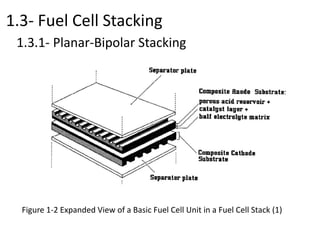
1.3- Fuel Cell Stacking
Stacking to achieve the voltage and power output level required.
- Planar-Bipolar Stacking
- Stacks with Tubular Cells
1.3.1- Planar-Bipolar Stacking
Individual unit cells are electrically connected with interconnects.
Because of the configuration of a flat plate cell, the interconnect
becomes a separator plate with two functions:
- to provide an electrical series connection between adjacent
cells, specifically for flat plate cells.
- to provide a gas barrier that separates the fuel and oxidant
of adjacent cells.
1.3- Fuel Cell Stacking
1.3.1- Planar-Bipolar Stacking
Figure 1-2 Expanded View of a Basic Fuel Cell Unit in a Fuel Cell Stack (1)
1.3- Fuel Cell Stacking
1.3.1- Planar-Bipolar Stacking
Planar-bipolar stacks can be further characterized according to
arrangement of the gas flow:
• Cross-flow. Air and fuel flow perpendicular to each other
• Co-flow. Air and fuel flow parallel and in the same
direction. In the case of circular cells, this means the
gases flow radially outward
• Counter-flow. Air and fuel flow parallel but in opposite
directions.
• Serpentine flow. Air or fuel follow a zig-zag path
• Spiral flow. Applies to circular cells
1.3- Fuel Cell Stacking
1.3.2 Stacks with Tubular Cells
- Especially for high-temperature fuel cells
- have significant advantages in sealing and in the structural
integrity of the cells.
- geometric challenge to the stack designer for high power
density and short current paths.
- The cell arrays can be connected in series or in parallel.
1.3.1- Planar-Bipolar Stacking
The manifold of gas streams to the cells in bipolar stacks can be
achieved in various ways:
- Internal: the manifolds run through the unit cells
- Integrated: the manifolds are integrated in the interconnects
- External: the manifold is completely external to the cell.

Fuel cell stacking

  • 1.
    1.3- Fuel CellStacking Stacking to achieve the voltage and power output level required. - Planar-Bipolar Stacking - Stacks with Tubular Cells 1.3.1- Planar-Bipolar Stacking Individual unit cells are electrically connected with interconnects. Because of the configuration of a flat plate cell, the interconnect becomes a separator plate with two functions: - to provide an electrical series connection between adjacent cells, specifically for flat plate cells. - to provide a gas barrier that separates the fuel and oxidant of adjacent cells.
  • 2.
    1.3- Fuel CellStacking 1.3.1- Planar-Bipolar Stacking Figure 1-2 Expanded View of a Basic Fuel Cell Unit in a Fuel Cell Stack (1)
  • 3.
    1.3- Fuel CellStacking 1.3.1- Planar-Bipolar Stacking Planar-bipolar stacks can be further characterized according to arrangement of the gas flow: • Cross-flow. Air and fuel flow perpendicular to each other • Co-flow. Air and fuel flow parallel and in the same direction. In the case of circular cells, this means the gases flow radially outward • Counter-flow. Air and fuel flow parallel but in opposite directions. • Serpentine flow. Air or fuel follow a zig-zag path • Spiral flow. Applies to circular cells
  • 4.
    1.3- Fuel CellStacking 1.3.2 Stacks with Tubular Cells - Especially for high-temperature fuel cells - have significant advantages in sealing and in the structural integrity of the cells. - geometric challenge to the stack designer for high power density and short current paths. - The cell arrays can be connected in series or in parallel. 1.3.1- Planar-Bipolar Stacking The manifold of gas streams to the cells in bipolar stacks can be achieved in various ways: - Internal: the manifolds run through the unit cells - Integrated: the manifolds are integrated in the interconnects - External: the manifold is completely external to the cell.