Wien Bridge Oscillator
Awien bridge oscillator is a type of phase
shift oscillator which is based upon a wien bridge
network comparsing of four arms are connected in a
bridge fashion here two arms are purely resistive
while the other two arms are a combination of
resistor and capacitor
5.
In particular onearm has a resistor and
capacitor connected in a series( And ) while
the other has them in parallel (And )
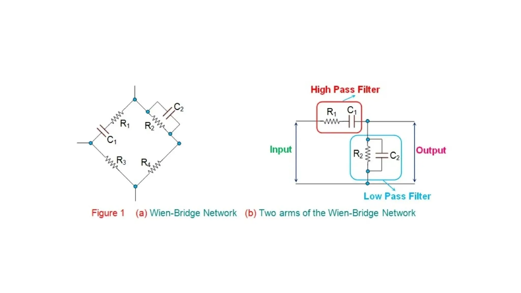
This indicates that these two arms of
the network behave identical to the high pass
filter or low pass filter mimicking the
behaviour of the circuit
7.
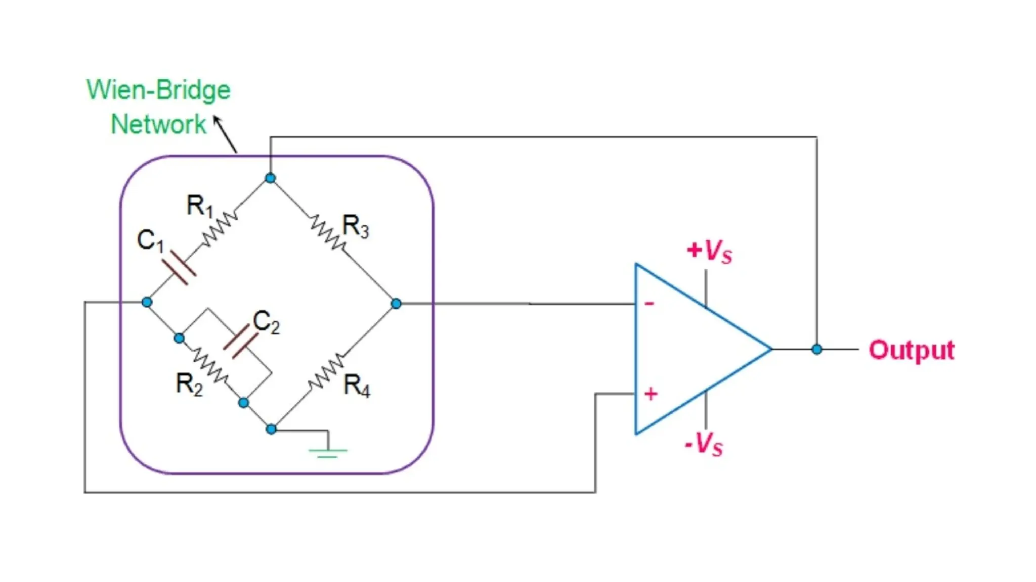
DERIVATION OF FREQUENCY
Thefeed back network of wien bridge oscillator
The two arms which are andand ,in parallel are frequency sensitive arms and hence only those
arms are considered
Input to feedback nrtwork isappilied between 1 and 3 which is amplifer output
8.
The wien bridgeoscillator is also an RC oscillator
which uses wien bridge circuit as its feed back network
The ampilifer used in this oscillator is a non
inverting amplifier which does not introduce any phase
shift
The feedback network which is a wien bridge
circuit also does not introduce any phase shift
9.
Thus phase shiftaround a loop in a wien
bridge oscillator is 0
The output of the amplifer is applied
between terminals 1 and 3 while ampilfer is
supplied from terminals 2 and 4 which is the
output of te feed back network
The basic circuit of wien bridge
oscillator is shown above
10.
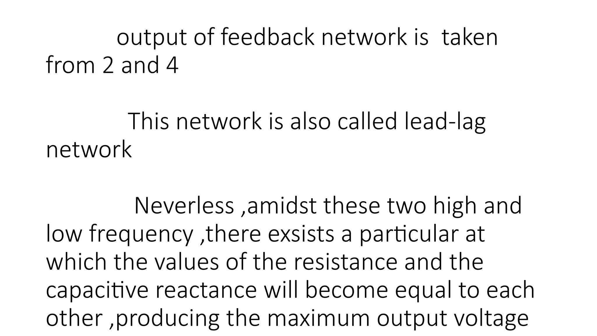
output of feedbacknetwork is taken
from 2 and 4
This network is also called lead-lag
network
Neverless ,amidst these two high and
low frequency ,there exsists a particular at
which the values of the resistance and the
capacitive reactance will become equal to each
other ,producing the maximum output voltage
11.
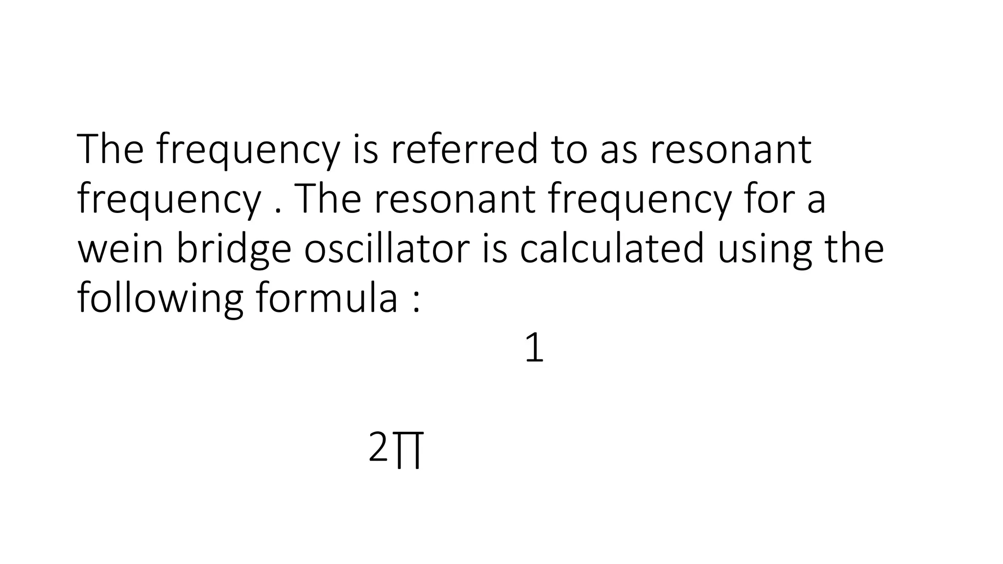
The frequency isreferred to as resonant
frequency . The resonant frequency for a
wein bridge oscillator is calculated using the
following formula :
1
2∏
Further ,as thisfrequency ,the phase
shift between the input and the output
willbecome zero and the magnitude of the
output voltage will become equal to one –
third of the input value .in addition ,it is seen
that the wien- bridge will be balanced only at
this particular frequency.