The document discusses the FPGA implementation of the Goertzel algorithm for spectrum analysis, aiming to provide a low power and area-efficient solution compared to the traditional FFT method. It details the project's scope, methodology, and the design of a real-time sweep spectral extractor using the Goertzel algorithm, highlighting the advantages of this approach in low-resource settings. Simulation results validate the efficiency and accuracy of the algorithm within an FPGA environment.
![ACEEE Int. J. on Control System and Instrumentation, Vol. 02, No. 03, October 2011
FPGA Implementation of Large Area Efficient and
Low Power Geortzel Algorithm for
Spectrum Analyzer
S Nagakishore B1, Vaujadevi M2, Renuka3, N Mohan Reddy4, S Pradeep kumar Reddy5,
1, 3
Aurora’s Technological & Research Institute, E.C.E Dept., Hyderabad, India
Email: {kishorereddy.vlsi, satyabhavanam}@gmail.com
2, 4, 5
Bandari Srinivas Institute of Technology, E.C.E Dept., Hyderabad, India
Email: {vasujadevi, pradeepkumarreddys, nalabolumohanreddy}@gmail.com
Abstract—Spectrum analysis is very essential requirement in It is simply the complex FFT. Normally, the magnitude of the
instrumentation and communication signal interception spectrum is displayed. The magnitude is the square root of
.Spectrum analysis is normally carried out by online or offline the FFT times its complex conjugate. (Square root of the sum
FFT processing. But the FFT being highly mathematical
of the real (sine) part squared and the imaginary (cosine) part
intensive, is not suitable for low area and low power
applications. Offline FFT processing can’t give the real time
squared.) The magnitude is a real quantity and represents
spectrum estimation which is essential in communication the total signal amplitude in each frequency bin, independent
signal interception. Online FFT computation takes very high of phase. If there is phase information in the spectrum, i.e.
resources, which makes the system costly and power hungry. the time record is triggered in phase with some component of
The Goertzel algorithm is a digital signal processing (DSP) the signal, then the real (cosine) or imaginary (sine) part or
technique for identifying frequency components of a signal, the phase may be displayed. The phase is simply the
published by Dr. Gerald Goertzel in 1958. While the general arctangent of the ratio of the imaginary and real parts of each
Fast Fourier transform (FFT) algorithm computes evenly frequency component. The phase is always relative to the
across the bandwidth of the incoming signal, the Goertzel
start of the triggered time record.
algorithm looks at specific, predetermined frequency. However
the implementation of Goertzel algorithm for spectrum
Fourier’s theorem states that any waveform in the time
computation is not explored for FPGA implementation. The domain can be represented by the weighted sum of sines and
FPGA being capable of offering high frequency data paths in cosines. The FFT spectrum analyzer samples the input signal,
them become suitable for realizing high speed spectrum computes the magnitude of its sine and cosine components,
analysis algorithms. and displays the spectrum of these measured frequency
In this project Goertzel algorithm will be implemented as components. [2-5] For one thing, some measurements which
high Q band pass filter on FPGA reconfigurable architecture. are very hard in the time domain are very easy in the
VHDL will be used for code development. A digital frequency frequency domain. Consider the measurement of harmonic
synthesizer produces frequency sweep which will drive the
distortion. It’s hard to quantify the distortion of a sine wave
digital mixer. The digital mixer output is given to the Goerzel
by looking at the signal on an oscilloscope. when the same
algorithm block. This algorithm output will be given to peak
detection logic. The peak detector block output will be used signal is displayed on a spectrum analyzer, the harmonic
for spectrum computation. The top level module integrates frequencies and amplitudes are displayed with amazing clarity.
all these modules with appropriate clock and control circuitry. An FFT spectrum analyzer works in an entirely different
The results will be demonstrated by applying the deterministic way. The input signal is digitized at a high sampling rate,
signals such as SIN wave and also with random band limited similar to a digitizing oscilloscope. Nyquist’s theorem says
signals. It will be aimed to achieve 32 steps in the band of that as long as the sampling rate is greater than twice the
operation for spectrum computation on Spartan 3E low cost highest frequency component of the signal, the sampled data
FPGA. Modelsim tool will be used for simulation. Xilinx ISE
will accurately represent the input signal. To make sure that
will be used for synthesis and programming the FPGA. Xilinx
Nyquist’s theorem is satisfied; the input signal passes
Chipscope will be used on chip verification of results.
through an analog filter which attenuates all frequency
Keywords: FFT, Goertzel algorithm, Spectrum Analysis, VHDL, components above 156 kHz by 90 dB. This is the anti-aliasing
XilinX ISE, Modelsim, Spartan 3E-FPGA board. filter. The resulting digital time record is then mathematically
transformed into a frequency spectrum using an algorithm
I. INTRODUCTION known as the Fast Fourier Transform, or FFT[10].
Spectrum Computation Techniques B. Real time sweep spectral extraction algorithm :
The system function block of a Real time sweep spectral
A. Spectrum computation by FFT: extractor is illustrated in the below figure. The mixer combines
The spectrum is the basic measurement of an FFT analyzer. the input test signal and reference signal from the local
© 2011 ACEEE 7
DOI: 01.IJCSI.02.03.19](https://image.slidesharecdn.com/19-120912005803-phpapp02/85/FPGA-Implementation-of-Large-Area-Efficient-and-Low-Power-Geortzel-Algorithm-for-Spectrum-Analyzer-1-320.jpg)
![ACEEE Int. J. on Control System and Instrumentation, Vol. 02, No. 03, October 2011
FPGA Implementation of Large Area Efficient and
Low Power Geortzel Algorithm for
Spectrum Analyzer
S Nagakishore B1, Vaujadevi M2, Renuka3, N Mohan Reddy4, S Pradeep kumar Reddy5,
1, 3
Aurora’s Technological & Research Institute, E.C.E Dept., Hyderabad, India
Email: {kishorereddy.vlsi, satyabhavanam}@gmail.com
2, 4, 5
Bandari Srinivas Institute of Technology, E.C.E Dept., Hyderabad, India
Email: {vasujadevi, pradeepkumarreddys, nalabolumohanreddy}@gmail.com
Abstract—Spectrum analysis is very essential requirement in It is simply the complex FFT. Normally, the magnitude of the
instrumentation and communication signal interception spectrum is displayed. The magnitude is the square root of
.Spectrum analysis is normally carried out by online or offline the FFT times its complex conjugate. (Square root of the sum
FFT processing. But the FFT being highly mathematical
of the real (sine) part squared and the imaginary (cosine) part
intensive, is not suitable for low area and low power
applications. Offline FFT processing can’t give the real time
squared.) The magnitude is a real quantity and represents
spectrum estimation which is essential in communication the total signal amplitude in each frequency bin, independent
signal interception. Online FFT computation takes very high of phase. If there is phase information in the spectrum, i.e.
resources, which makes the system costly and power hungry. the time record is triggered in phase with some component of
The Goertzel algorithm is a digital signal processing (DSP) the signal, then the real (cosine) or imaginary (sine) part or
technique for identifying frequency components of a signal, the phase may be displayed. The phase is simply the
published by Dr. Gerald Goertzel in 1958. While the general arctangent of the ratio of the imaginary and real parts of each
Fast Fourier transform (FFT) algorithm computes evenly frequency component. The phase is always relative to the
across the bandwidth of the incoming signal, the Goertzel
start of the triggered time record.
algorithm looks at specific, predetermined frequency. However
the implementation of Goertzel algorithm for spectrum
Fourier’s theorem states that any waveform in the time
computation is not explored for FPGA implementation. The domain can be represented by the weighted sum of sines and
FPGA being capable of offering high frequency data paths in cosines. The FFT spectrum analyzer samples the input signal,
them become suitable for realizing high speed spectrum computes the magnitude of its sine and cosine components,
analysis algorithms. and displays the spectrum of these measured frequency
In this project Goertzel algorithm will be implemented as components. [2-5] For one thing, some measurements which
high Q band pass filter on FPGA reconfigurable architecture. are very hard in the time domain are very easy in the
VHDL will be used for code development. A digital frequency frequency domain. Consider the measurement of harmonic
synthesizer produces frequency sweep which will drive the
distortion. It’s hard to quantify the distortion of a sine wave
digital mixer. The digital mixer output is given to the Goerzel
by looking at the signal on an oscilloscope. when the same
algorithm block. This algorithm output will be given to peak
detection logic. The peak detector block output will be used signal is displayed on a spectrum analyzer, the harmonic
for spectrum computation. The top level module integrates frequencies and amplitudes are displayed with amazing clarity.
all these modules with appropriate clock and control circuitry. An FFT spectrum analyzer works in an entirely different
The results will be demonstrated by applying the deterministic way. The input signal is digitized at a high sampling rate,
signals such as SIN wave and also with random band limited similar to a digitizing oscilloscope. Nyquist’s theorem says
signals. It will be aimed to achieve 32 steps in the band of that as long as the sampling rate is greater than twice the
operation for spectrum computation on Spartan 3E low cost highest frequency component of the signal, the sampled data
FPGA. Modelsim tool will be used for simulation. Xilinx ISE
will accurately represent the input signal. To make sure that
will be used for synthesis and programming the FPGA. Xilinx
Nyquist’s theorem is satisfied; the input signal passes
Chipscope will be used on chip verification of results.
through an analog filter which attenuates all frequency
Keywords: FFT, Goertzel algorithm, Spectrum Analysis, VHDL, components above 156 kHz by 90 dB. This is the anti-aliasing
XilinX ISE, Modelsim, Spartan 3E-FPGA board. filter. The resulting digital time record is then mathematically
transformed into a frequency spectrum using an algorithm
I. INTRODUCTION known as the Fast Fourier Transform, or FFT[10].
Spectrum Computation Techniques B. Real time sweep spectral extraction algorithm :
The system function block of a Real time sweep spectral
A. Spectrum computation by FFT: extractor is illustrated in the below figure. The mixer combines
The spectrum is the basic measurement of an FFT analyzer. the input test signal and reference signal from the local
© 2011 ACEEE 7
DOI: 01.IJCSI.02.03.19](https://image.slidesharecdn.com/19-120912005803-phpapp02/75/FPGA-Implementation-of-Large-Area-Efficient-and-Low-Power-Geortzel-Algorithm-for-Spectrum-Analyzer-1-2048.jpg)
![ACEEE Int. J. on Control System and Instrumentation, Vol. 02, No. 03, October 2011
oscillator. The output modulated signals will have the sum Applying an additional, FIR, transform of the form[1]
and difference frequency signals[7].
The peak detector will detect the signal intensity, and
send it to the X-Y scope. The sweep generator supports the
will give an overall transform of
x-axis signal, and pushes the local oscillator to generate the
reference signal with the desired frequency. We adopt the
Direct Digital Synthesis (DDS) technique to tune the refer-
ence signal .To meet the rather narrow band requirement, we The time-domain equivalent of this overall transform is
need very high Q FIR band pass filter. It implies hundreds of
tap orders.
Which becomes, assuming x (k) = 0 for all k < 0
Or, the equation for the (n + 1)-sample DFT of x, evaluated
for ω and multiplied by the scale factor e + 2πiωn. Note that
applying the additional transform Y (z)/S (z) only requires the
last two samples of the s sequence. Consequently, upon
Fig 1.The system function block of a Real time sweep spectral processing N samples x(0)...x(N - 1), the last two samples from
extra ctor the s sequence can be used to compute the value of
C. Goertzel algorithm: a DFT bin, which corresponds to the chosen frequency ω as
X (ω) = y(N - 1)e - 2πiω(N - 1) = (s(N - 1) - e - 2πiωs(N - 2))e - 2πiω(N - 1)
The Goertzel algorithm is a digital signal processing (DSP)
For the special case often found when computing DFT bins,
technique for identifying frequency components of a signal,
where ωN = k for some integer, k, this simplifies to
published by Dr. Gerald Goertzel in 1958. While the
X (ω) = (s(N - 1) - e - 2πiωs(N - 2))e + 2πiω = e + 2πiωs(N - 1) - s(N - 2)
general Fast Fourier transform (FFT) algorithm computes
In either case, the corresponding power can be computed
evenly across the bandwidth of the incoming signal, the
using the same cosine term required to compute s as
Goertzel algorithm looks at specific, predetermined
X (ω) X’ (ω) = s (N - 2)2 + s (N - 1)2 - 2cos (2πω) s (N - 2) s (N -
frequencies. Some applications require only a few DFT
1)
frequencies. [1] One example is frequency-shift keying
To compute a single DFT bin for a complex sequence of
(FSK) demodulation, in which typically two frequencies are
length N, this algorithm requires 2N multiplications and
used to transmit binary data; another example is DTMF, or
4N additions/subtractions within the loop, as well as 4
touch-tone telephone dialing, in which a detection circuit
multiplications and 4 additions/subtractions to compute X(ω),
must constantly monitor the line for two simultaneous
for a total of 2N+4 multiplications and 4N+4 additions/
frequencies indicating that a telephone button is
subtractions (for real sequences, the required operations are
depressed. Goertzel’s algorithm reduces the number of real-
half that amount). In contrast, the Fast Fourier
valued multiplications by almost a factor of two relative to
transform (FFT) requires 2log 2N multiplications and
direct computation via the DFT equation[9]. For a length of
3log2N additions/subtractions per DFT bin, but must compute
N, the Goertzel’s series is all N bins simultaneously .When the number of
desired DFT bins, M, is small it is computationally
advantageous to implement the Goertzel algorithm, rather
than the FFT. Approximately, this occurs when
The Goertzel algorithm computes a sequence, s (n), given an
input sequence, x (n): or if, for some reason, N is not an integral power of 2 while
S (n) = x (n) + 2cos (2πω) s (n - 1) - s (n - 2) you stick to a simple FFT algorithm like the 2-radix Cooley-
Where s (- 2) = s (- 1) = 0 and ω is some frequency of interest, Tukey FFT algorithm, and zero-padding the samples out to
in cycles per sample, which should be less than 1/2. This an integral power of 2 would violate
effectively implements a second-order one addition and one
subtraction per input sample. For real inputs, these operations
are real. The Z transform of this process is Moreover, the Goertzel algorithm can be computed as samples
come in, and the FFT algorithm may require a large table
of N pre-computed sines and cosines to be efficient.
© 2011 ACEEE 8
DOI: 01.IJCSI.02.03.19](https://image.slidesharecdn.com/19-120912005803-phpapp02/85/FPGA-Implementation-of-Large-Area-Efficient-and-Low-Power-Geortzel-Algorithm-for-Spectrum-Analyzer-2-320.jpg)
![ACEEE Int. J. on Control System and Instrumentation, Vol. 02, No. 03, October 2011
II. SCOPE OF THE PROJECT
In this project we implement the Goertzel algorithm on
FPGA using VHDL and implementing the spectrum estimation
logic around Goertzel algorithm. As on today the spectrum
computation is done with FFT based architectures. In case
of online FFT computation the required resources are very
high and power consumption is also high. In case of offline
FFT computation real time applications can be built. The
Proposed solution is that The Goertzel algorithm is used as
band pass filter with a mixer stage preceding to it, for spectrum
estimation. This will be low power and low area solution with
respect to FFT.[1] The below figure shows the system function
block of 1 real-time sweep spectral extractor with Goertzel
algorithm.
IV. IMPLEMENTATION OF SPECTRUM ANALYZER
Top level design:
The detailed block diagram of the top level module is
shown in the below fig.
Fig 2. System function block of 1 real-time sweep spectral
Extractor with Goertzel algorithm
The below figure is the corresponding second order
recursive calculation flow. Here, it is apparently that Goertzel
algorithm only needs two real multiplications and three real
additions to pick up the amplitude of the specified frequency
component. In the above block diagram the DDS based LO generates the
Numerically Controlled Oscillator (NCO) that will be one of
the input signal to the mixer and the other input to mixer is the
input test signal [11-14].The mixer will combine these two
signals and generates a signal which is the difference between
these two signals .The output signal of the mixer is at a
frequency that the Goertzel algorithm is working and the
Goertzel algorithm will identify the frequency components of
the signal. The Goertzel algorithm will generate the frequency
components of a signal in terms of the real and imaginary
parts that will be applied to the input of the magnitude
Fig 3 Calculation flow of the second order recursive algorithm calculator followed by peak detector which determines the
Conventionally for high frequency resolution we need narrow peak of the signal.
pass band of FIR filter and consume too much chip area. The FPGA Spectrum analyzer controller controls the all
Without pass band narrowing, The Goertzel algorithm blocks like frequency bin counter and sample counter. The
calculates and extracts the amplitude of the specified sample counter counts the samples, when ever this counter
frequency component .We can achieve better efficiency reaches the maximum value the frequency bin counter is
without high chip area requirement. incremented by one and the sample counter again starts
counting until the entire spectrum is covered by the frequency
III. IMPLEMENTATION OF GOERTZEL ALGORITHM bin counter. The Phase Increment generator generates the
corresponding Phase increments for the DDS Core.
Goertzel algorithm:
For a length of N, the Goertzel’s series is
© 2011 ACEEE 9
DOI: 01.IJCSI.02.03. 19](https://image.slidesharecdn.com/19-120912005803-phpapp02/85/FPGA-Implementation-of-Large-Area-Efficient-and-Low-Power-Geortzel-Algorithm-for-Spectrum-Analyzer-3-320.jpg)
![ACEEE Int. J. on Control System and Instrumentation, Vol. 02, No. 03, October 2011
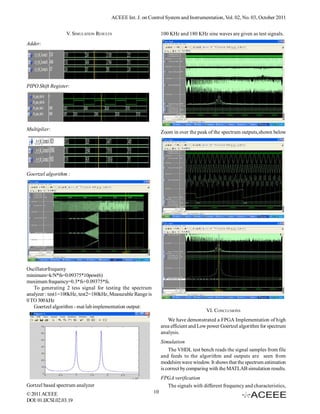
kept in FPGA memory as test inputs. The algorithm output [10] Brigham, “The Fast Fourier Transform and Its applications”,
verified with chipscope tool. Area utilization from synthesis Prentice-Hall Inc.
report , used to prove the area efficency. (in comparison with [11] Xilinx FPGA spartan 3E device data sheet.
[12] Agilent(2004), “Swept and FFT Analysis”. Performance
the standard area occupancy of FFT core) Power analysis,
Spectrum Analyzer Series-Application note,Agilent.
carried out using Xilinx Xpower tool.
[13] Brigham, “The Fast Fourier Transform and Its applications”
Prentice-Hall Inc.,1988.
ACKNOWLEDGMENTS [14] Tectonics, “Fundamentals of Real-Time Spectrum Analysis”,
Technical Report.
We would like to thank the Faculty of Bandari Institute of
Science and Technology(BSIT) & Aurora’s Technological and About Authors
Research Institute(ATRI), for their support. We acknowledge S Nagakishore Bhavanam is an M.Tech Post-
Dr. Srinivasa Rao, Mr Madana Gopal and Latha S, help in the Graduate of VLSI-SD from Aurora’s Techno-
development and testing of our Implementation of “ Large logical & Research Institute (ATRI), Depart-
Area Efficient and Low Power Geortzel Algorithm for FPGA ment of ECE, JNTUH. He obtained his B.Tech
based Spectrum Analyzer”. from S.V.V.S.N Engineering college, Ongole. He
has 14 Months of teaching experience. He has 4
Research Papers, Published in IEEE Xplore, He
REFERENCES
has 3 International journal Publications and has
[1] FPGA based spectrum analyzer with high area efficiency 6 Papers, Published in International & National Conferences. His
by Goertzel algorithm, IEEE 2008, computer society, Image and interesting Fields are Low Power VLSI, Digital System Design,
signal processing. Sensor Networks and Communications.
[2] Agilent(2004), “Swept and FFT Analysis”. Performance Vasujadevi Midasala is an M.Tech Post-
spectrum analyzer series – application note, Agilent, 2004. Graduate of VLSI from Bandari Institute of
[3] Tectonics (2004), “Fundamentals of Real-Time Spectrum science & Technological (BSIT), Department of
Analysis”, Technical report, Tektronics, 2004. ECE, JNTUH. She obtained her B.Tech from
[4] Zhang, Q. Smit, G.J.M. Smit, L.T. Kokkeler, A. Hoeksema, S.V.V.S.N Engineering college Ongole. She Has 4
R.W. Heskamp, M., (2005), “A reconfigurable platform forcognitive Research Papers Published in International/
radio”, 2005 2nd International Conference on Mobile Technology, National Journals. Her interesting Fields are Low
Applications and Systems, 15-17 Nov. 2005. Power VLSI, Design for Testability.
[5] I.S. Uzun, A. Amira and A. Bouridane, (2005), “FPGA N Mohan Reddy is an M.Tech Post Graduate
implementations of fast Fourier transforms for real-time signal and of VLSI from C.V.S.R Engineering College,
image processing”, IEE Proc.-Vis. Image Signal Process., Vol. 152, Hyderabad, Department of Electronics and
No. 3, June 2005. Communications Engineering.. He obtained his
[6] Matteo Frigo and Steven G. Johnson, (2005), “The Design and B.Tech from Adams Engineering College,
Implementation of FFTW3”, Proc. IEEE, vol. 93, no. 2, pp. 216– Palvancha.He has 3 Years of Teaching
231 (2005). Experience.His Intresting fields are Low Power
[7] Min-chuan Lin, Guo-Ruey Tsai, Tsao-Kai Chang, Shi-Sheng VLSI and Digital SyStem Design.
Chu, (2005), “An Approach to FPGA-based Time-Frequency Sangala Pradeep Kumar Reddy is an M.Tech,
Spectrogram by Real-Time Sweep Spectral Extraction Algorithm”, Post Graduate from Vardhaman College of
Proceedings IEEE TENCON2005, 21-24 Nov. 2005, Melbourne, Engineering , Hyderabad ,Associate Professor
Victoria, Australia. & H.O.D, Department of E.C.E, Bandari
[8] Robert Beck, Andrew G. Dempster, and Izzet Kale, (2001), Srinivas Institute of Technology (BSIT). He
“Finite-Precision Goertzel Filters Used for Signal Tone Detection”, obtained his B.Tech from Vijay Narayana
IEEE transactions on circuits and systems—ii: analog and digital
signal processing, vol. 48, no. 6, june 2001, pp691-700.. Enginnering college, Bellary, Karnataka He Has more than 10 years
[9] Jacobsen, E., Lyons, R., (2003), “The sliding DFT”, Signal of teaching experience.
Processing Magazine, IEEE, Volume: 20, Issue: 2, Mar 2003, pp74 Renuka Roy is an M.Tech Post- Graduate of
VLSI from Auroras Technological & Research
Instittute, Hyderabad, Department of ECE,
JNTUH. She obtained her B.Tech from G
Narayanamma Engineering college,Hyderabad.
She has 8 months of Teaching Experince.Her
Intresting fields are VLSI and Communications.
© 2011 ACEEE 11
DOI: 01.IJCSI.02.03.19](https://image.slidesharecdn.com/19-120912005803-phpapp02/85/FPGA-Implementation-of-Large-Area-Efficient-and-Low-Power-Geortzel-Algorithm-for-Spectrum-Analyzer-5-320.jpg)