Downloaded 16 times


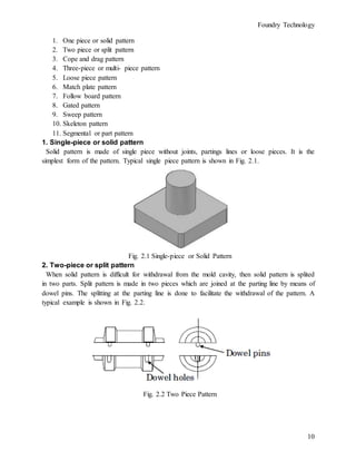
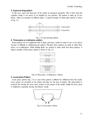
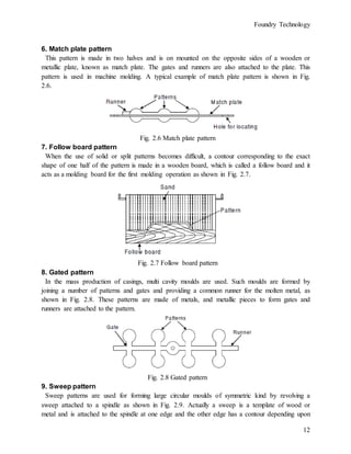
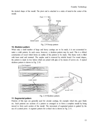

![Foundry Technology
52
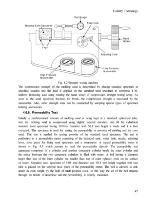
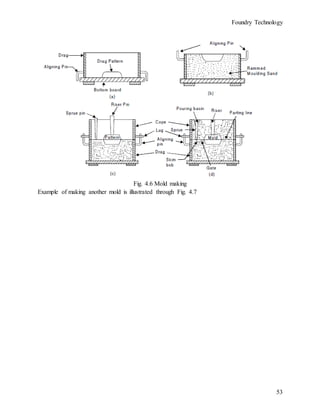
4.8. Steps Involved in Makinga Sand Mold
1. Initially a suitable size of molding box for creating suitable wall thickness is selected for a
two piece pattern. Sufficient care should also be taken in such that sense that the molding box
must adjust mold cavity, riser and the gating system (sprue, runner and gates etc.).
2. Next, place the drag portion of the pattern with the parting surface down on the bottom (ram-
up) board as shown in Fig. 4.6 (a).
3. The facing sand is then sprinkled carefully all around the pattern so that the pattern does not
stick with molding sand during withdrawn of the pattern.
4. The drag is then filled with loose prepared molding sand and ramming of the molding sand is
done uniformly in the molding box around the pattern. Fill the molding sand once again and
then perform ramming. Repeat the process three four times,
5. The excess amount of sand is then removed using strike off bar to bring molding sand at the
same level of the molding flask height to completes the drag.
6. The drag is then rolled over and the parting sand is sprinkled over on the top of the drag [Fig.
4.6(b)].
7. Now the cope pattern is placed on the drag pattern and alignment is done using dowel pins.
8. Then cope (flask) is placed over the rammed drag and the parting sand is sprinkled all around
the cope pattern.
9. Sprue and riser pins are placed in vertically position at suitable locations using support of
molding sand. It will help to form suitable sized cavities for pouring molten metal etc. [Fig.
4.6 (c)].
10. The gaggers in the cope are set at suitable locations if necessary. They should not be located
too close to the pattern or mold cavity otherwise they may chill the casting and fill the cope
with molding sand and ram uniformly.
11. Strike off the excess sand from the top of the cope.
12. Remove sprue and riser pins and create vent holes in the cope with a vent wire. The basic
purpose of vent creating vent holes in cope is to permit the escape of gases generated during
pouring and solidification of the casting.
13. Sprinkle parting sand over the top of the cope surface and roll over the cope on the bottom
board.
14. Rap and remove both the cope and drag patterns and repair the mold suitably if needed and
dressing is applied
15. The gate is then cut connecting the lower base of sprue basin with runner and then the mold
cavity.
16. Apply mold coating with a swab and bake the mold in case of a dry sand mold.
17. Set the cores in the mold, if needed and close the mold by inverting cope over drag.
18. The cope is then clamped with drag and the mold is ready for pouring, [Fig. 4.6 (d)].](https://image.slidesharecdn.com/foundrytechnologynote-210727094151/85/Foundry-technology-note-57-320.jpg)

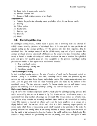
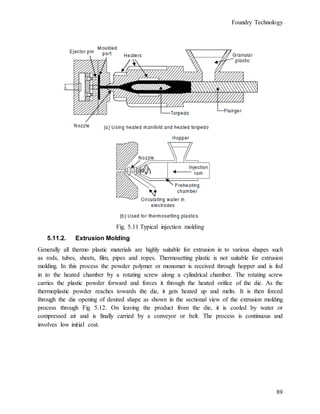


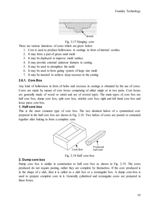
The document outlines a course on Foundry Technology, detailing the processes involved in making castings, including pattern making, molding, and casting techniques. It emphasizes the historical significance of foundry engineering, the advantages of the casting process, and the metallurgical benefits of cast alloys. Additionally, it discusses the stages of production, such as pattern making, melting, casting, and the importance of quality control in foundries.


