This document provides an overview of the NX 9.0 software for engineering design. It covers topics such as getting started in NX 9.0, the user interface, modeling tools like form features and sketching, drafting, and assembly modeling. The document contains 8 chapters that describe these various aspects of NX 9.0 through examples and exercises for creating models of different mechanical components and assemblies.


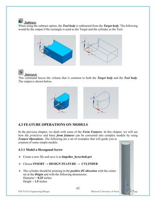
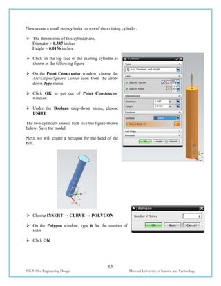
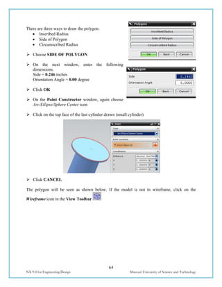
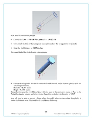
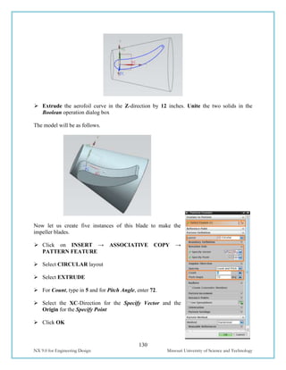
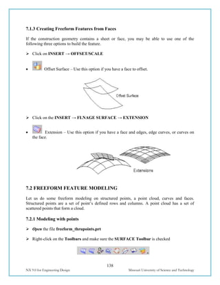
![22
NX 9.0 for Engineering Design Missouri University of Science and Technology
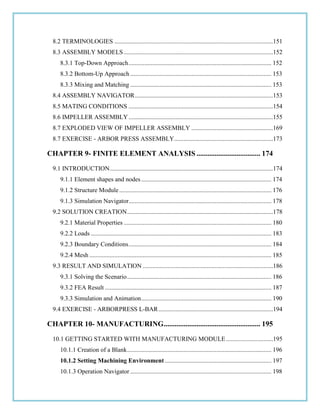
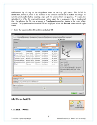
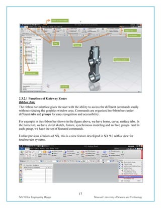
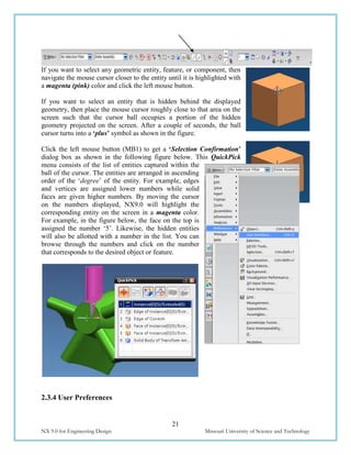
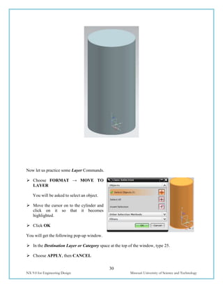
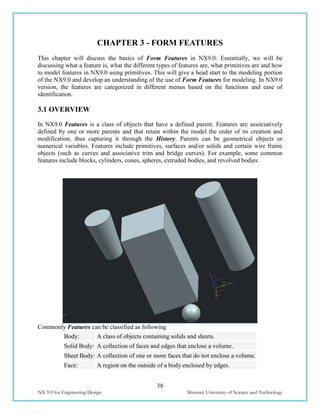
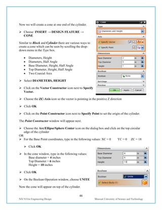
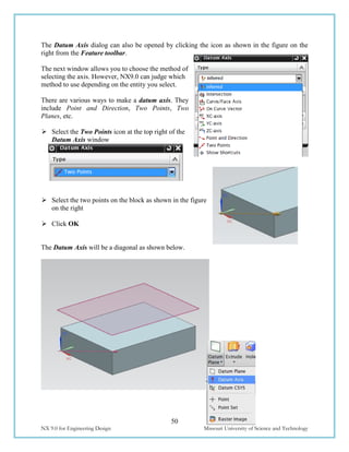
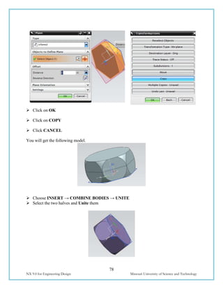
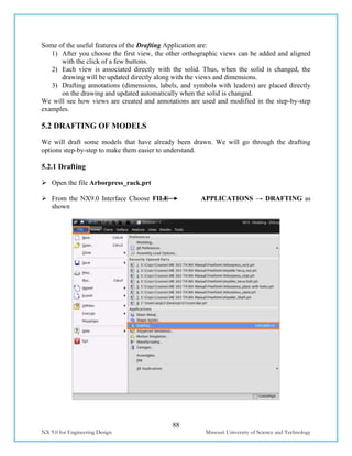
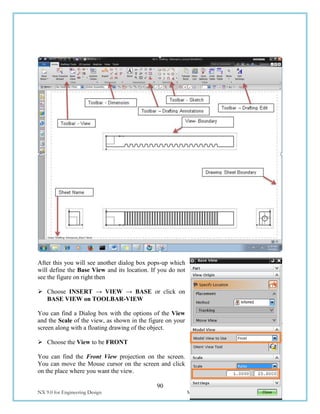
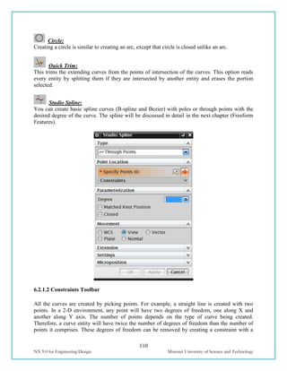
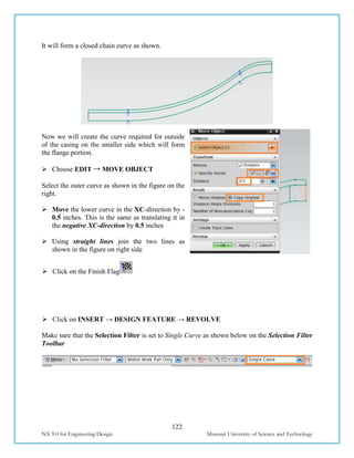
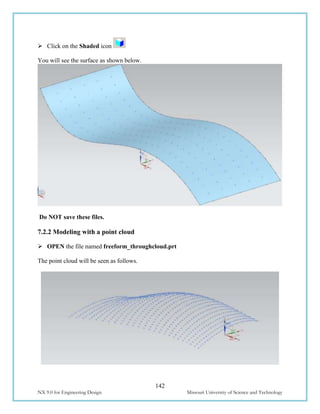
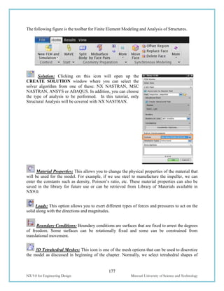
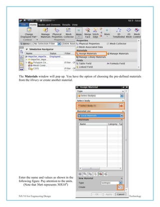
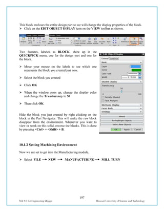
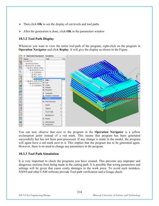
Choose PREFERENCES on the Menu button [located to top right of the main window] to
find the various options available
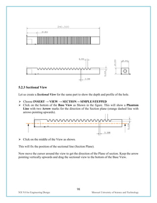
User Preferences are used to define the display parameters of new objects, names, layouts, and
views. You can set the layer, color, font, and width of created objects. You can also design
layouts and views, control the display of object and view names and borders, change the size of
the selection ball, specify the selection rectangle method, set chaining tolerance and method, and
design and activate a grid. Changes that you make using the Preferences menu override any
counterpart customer defaults for the same functions.
User Interface
Choose PREFERENCES→USER INTERFACE to find the options in the dialog box.
The User Interface option customizes how NX works and interacts to specifications you set.
You can control the location, size and visibility
status of the main window, graphics display, and
information window. You can set the number of
decimal places (precision) that the system uses for
both input text fields and data displayed in the
information window. You can also specify a full or
small dialog for file selection. You can also set
macro options and enable a confirmation dialog for
Undo operations.
The General tab allows you to set the precision
level as seen in the Information Window
The Layout tab allows you to set the location of
the Resource Bar
The Macro tab allows you to set the pause
while displaying animation
Visualization
Choose PREFERENCES →
VISUALIZATION to find the options in the
dialog box.
This dialog box controls attributes that affect the display
in the graphics window. Some attributes are associated
with the part or with particular Views of the part. The
settings for these attributes are saved in the part file. For
many of these attributes, when a new part or a view is
created, the setting is initialized to the value specified in](https://image.slidesharecdn.com/nx9-160608102546/85/NX9-for-Engineering-Design-28-320.jpg)

![166
NX 9.0 for Engineering Design Missouri University of Science and Technology
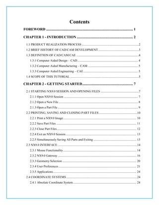
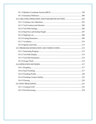
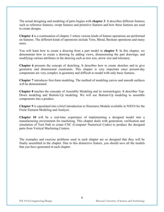
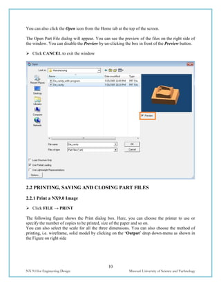
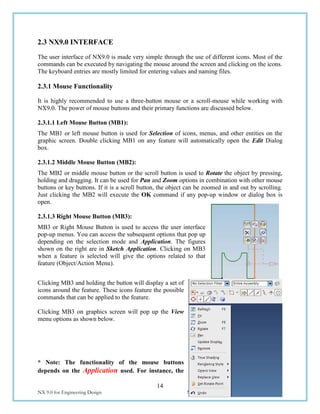
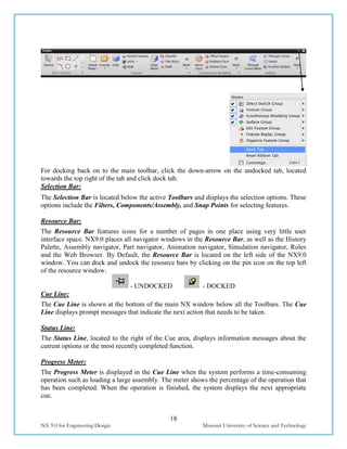
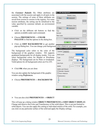
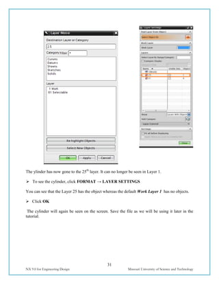
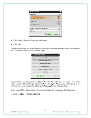
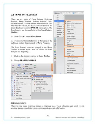
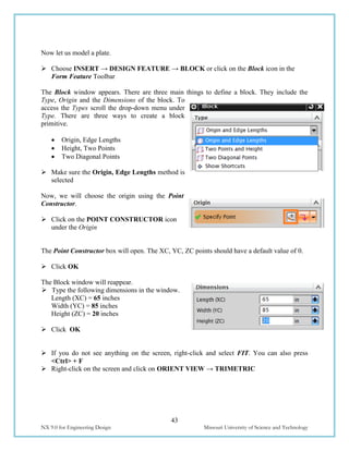
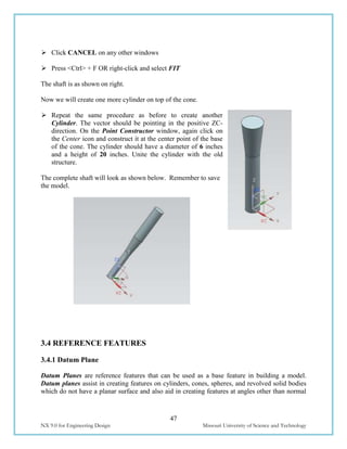
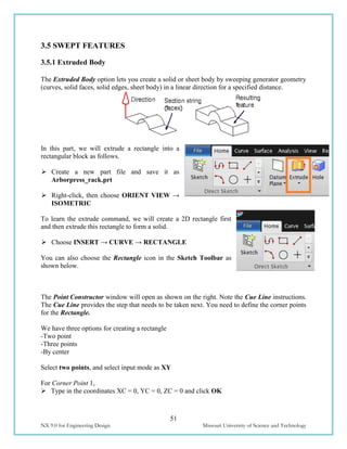
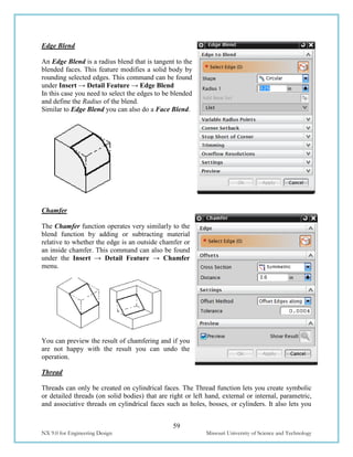
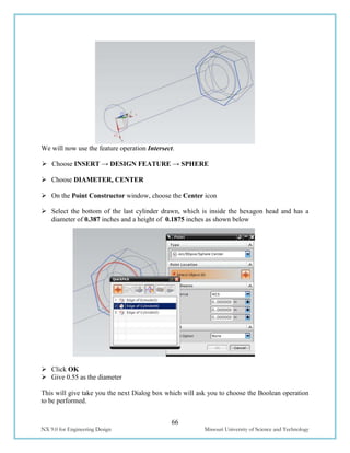
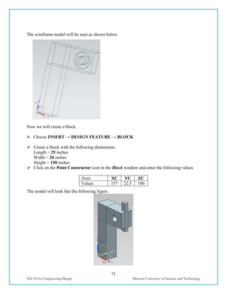
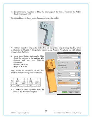
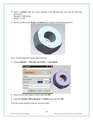
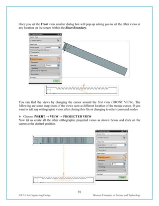
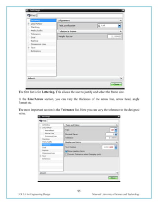
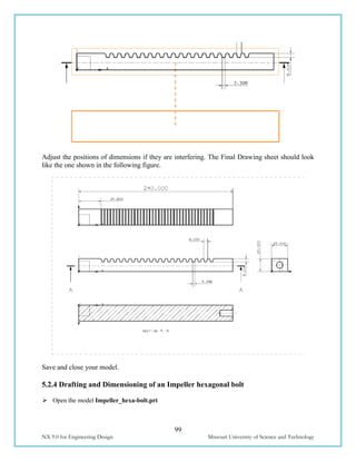
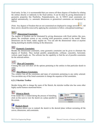
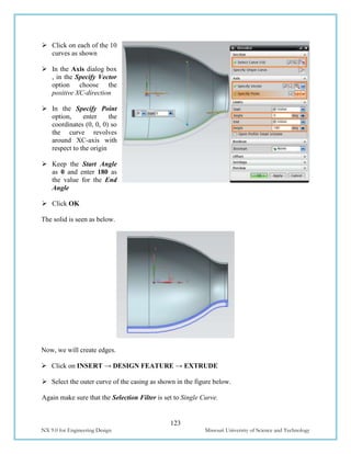
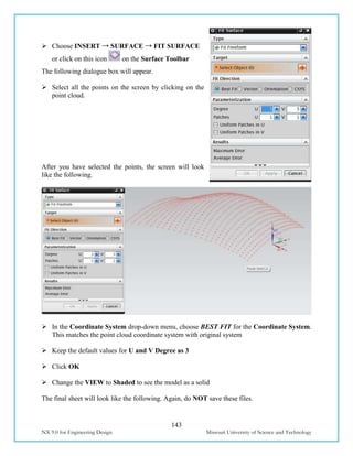
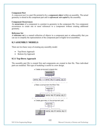
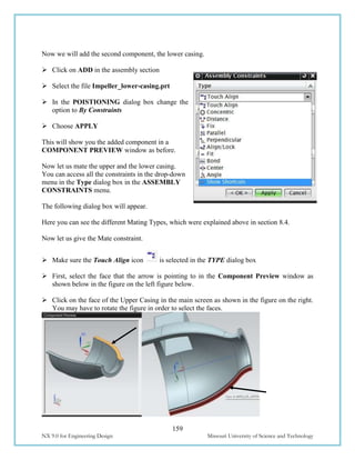
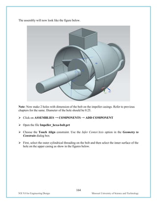
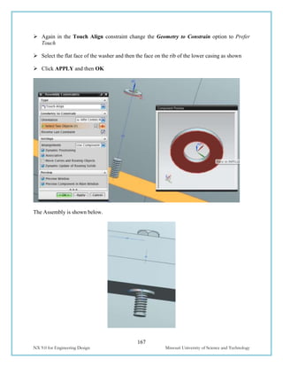
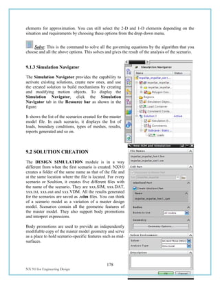
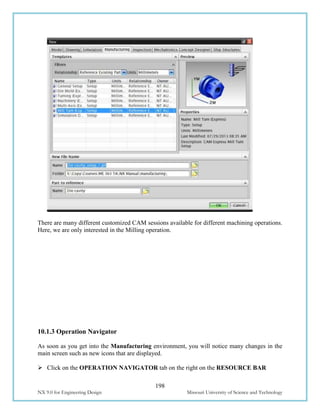
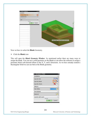
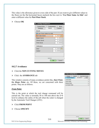
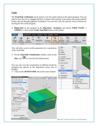
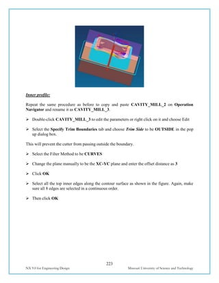
The assembly is shown below.
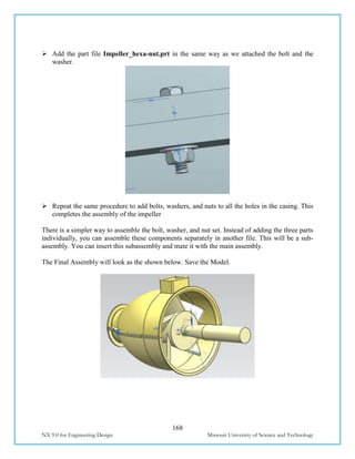
Repeat the same procedure as before to add the part file Impeller_washer.prt [create a
washer of inner diameter 0.25 and outer diameter 0.75]
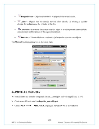
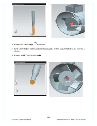
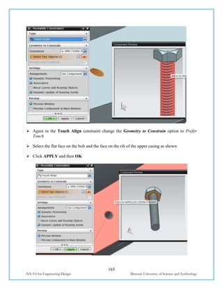
Choose the Touch Align constraint. Use the Infer Center/Axis option in the Geometry to
Constrain dialog box
Select the inner face of the washer and the cylindrical threading on the bolt as shown](https://image.slidesharecdn.com/nx9-160608102546/85/NX9-for-Engineering-Design-172-320.jpg)
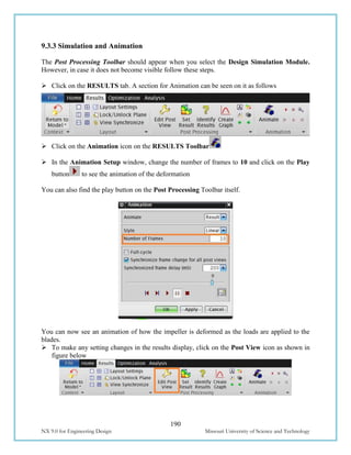
![169
NX 9.0 for Engineering Design Missouri University of Science and Technology
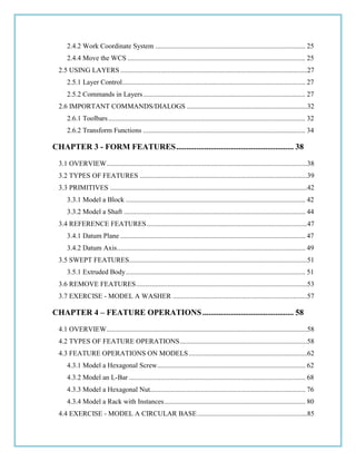
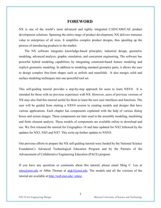
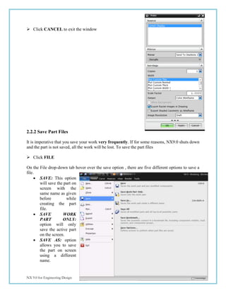
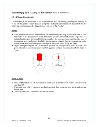
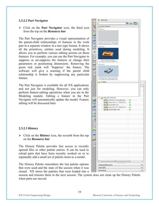
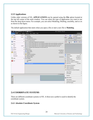
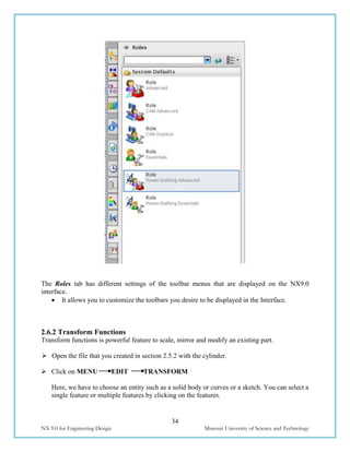
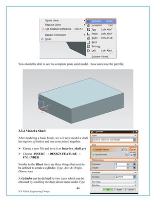
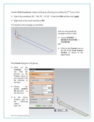
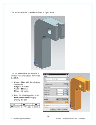
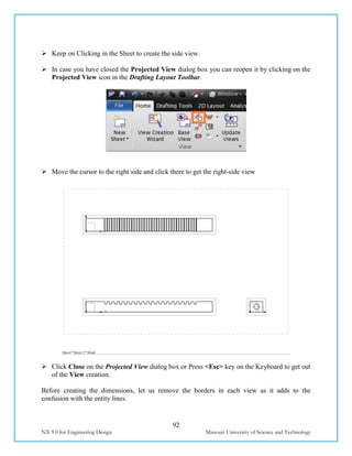
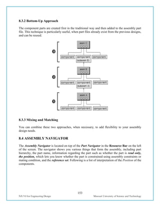
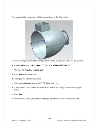
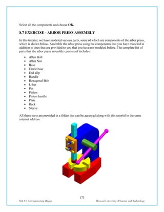
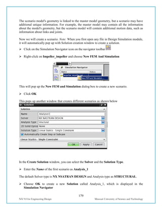
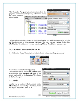
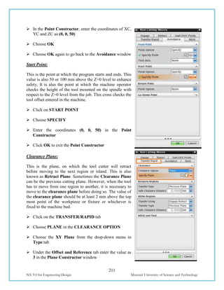
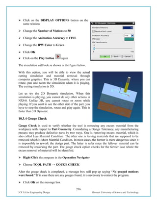
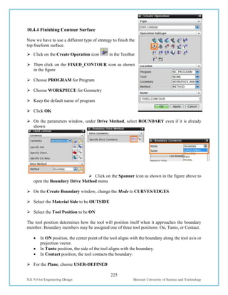
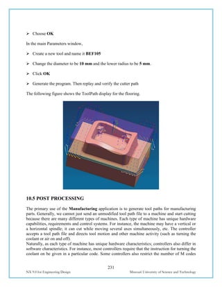
8.7 EXPLODED VIEW OF IMPELLER ASSEMBLY
In this section, we are going to create an Exploded view of the Assembly to show a separated
part-by-part picture of the components that make the assembly. In today’s industrial practice,
these kind of views are very helpful on the assembly shop floor to get a good idea of which item
fixes where. The user should understand that exploding an assembly does not mean relocation of
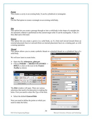
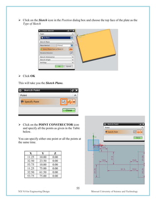
the components, but only viewing the models in the form of disassembly. You can ‘Unexplode’
the view at any time you want to regain the original assembly view. Let us explode the Impeller
Assembly.
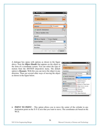
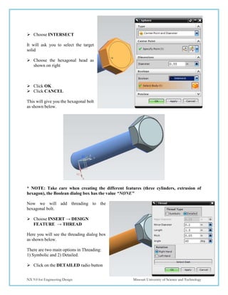
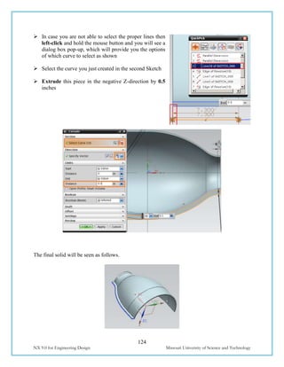
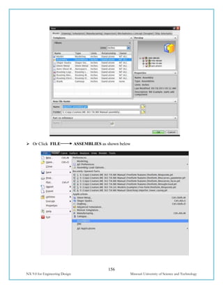
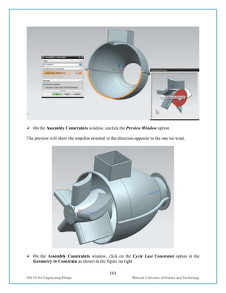
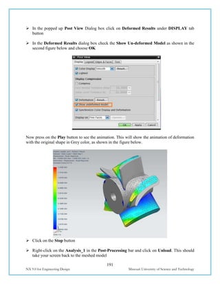
Choose MENU ASSEMBLIES→
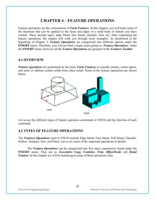
EXPLODED VIEWS → NEW EXPLOSION
This will pop a Dialog box asking for the name of the
Explosion view to be created. You can leave name as
the default name and choose OK
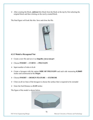
Now the UG environment is in Exploded view environment though you do not find any
difference. When we start exploding some assembly, we should decide upon a component to
keep that component as the reference. This component should not be moved from its original
position. In the case of the impeller assembly, the impeller will be the right option as it is central
to the entire assembly. Now let’s start exploding the components.
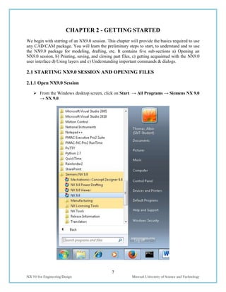
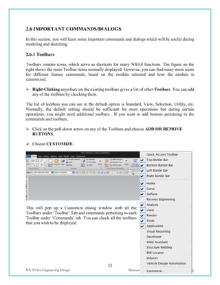
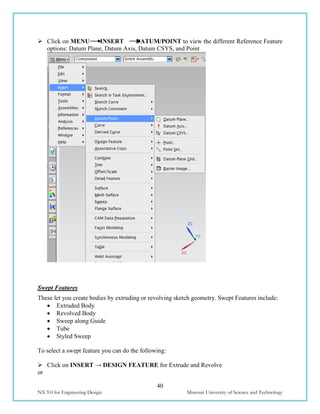
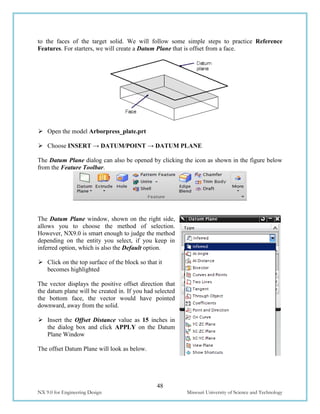
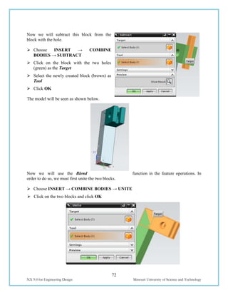
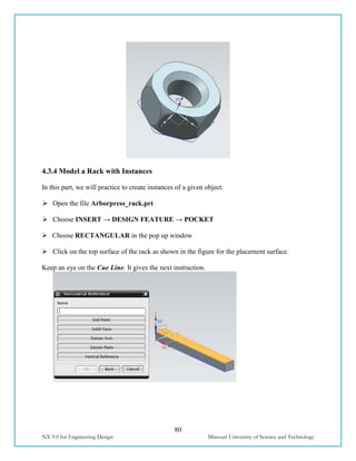
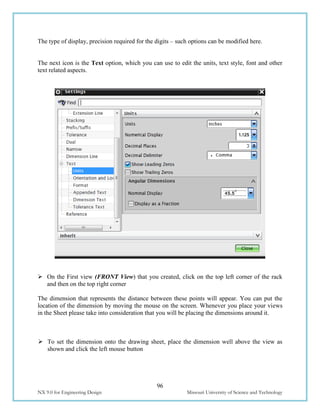
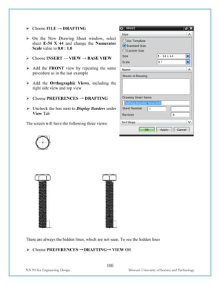
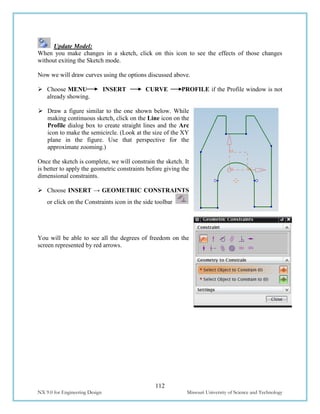
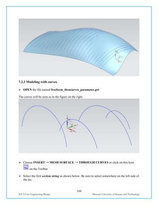
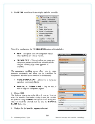
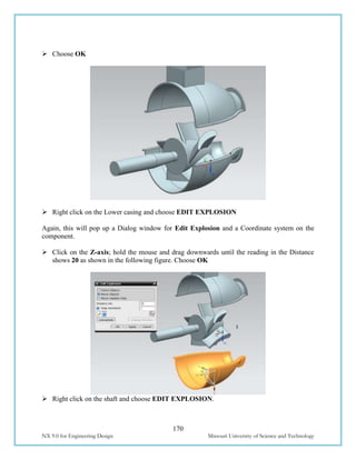
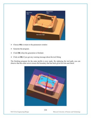
Right Click on the Upper casing and choose EDIT EXPLOSION
The Edit Explosion window will pop up along with a Coordinate system on the component.
Click on the Z axis; hold the mouse and drag upwards until the reading in the Distance
shows -20 [substitute +20 if you have designed in opposite direction] as shown in the
following figure.](https://image.slidesharecdn.com/nx9-160608102546/85/NX9-for-Engineering-Design-175-320.jpg)
![212
NX 9.0 for Engineering Design Missouri University of Science and Technology
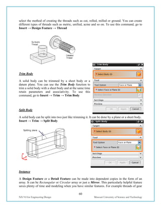
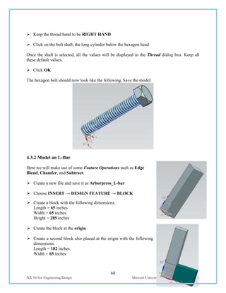
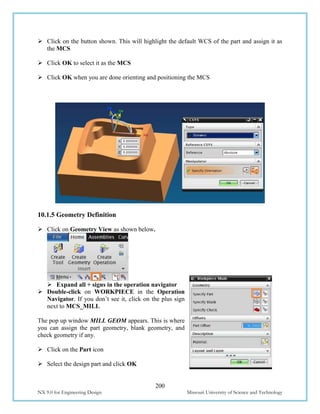
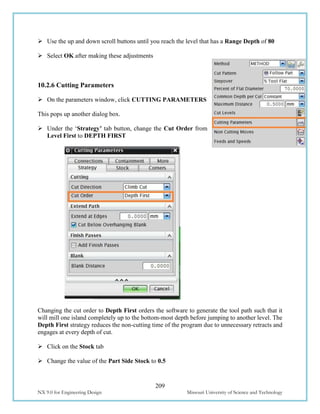
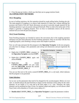
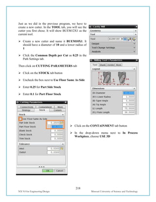
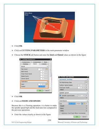
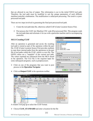
Click OK twice to go back to the CAVITY_MILL parameters window
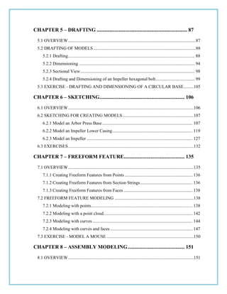
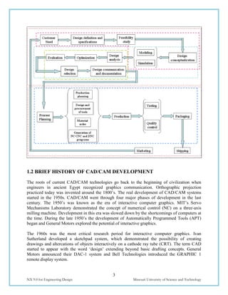
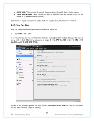
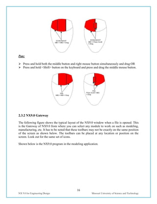
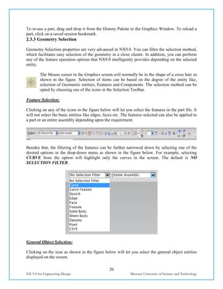
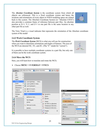
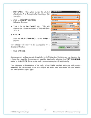
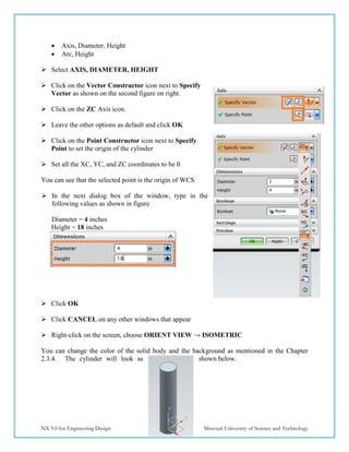
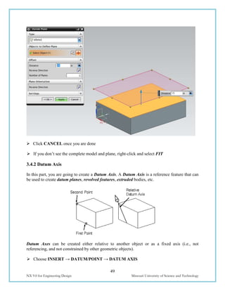
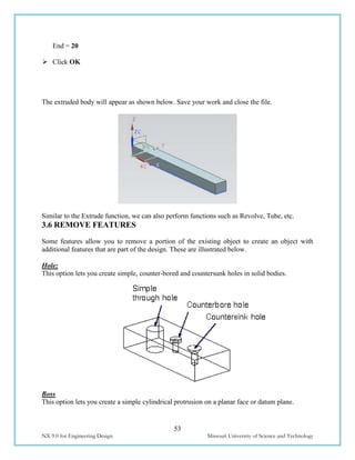
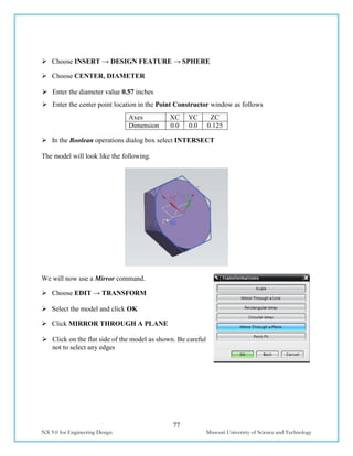
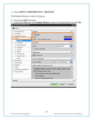
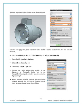
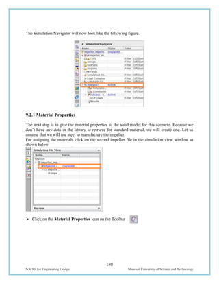
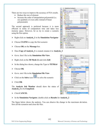
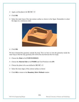
10.2.8 Speeds and Feeds
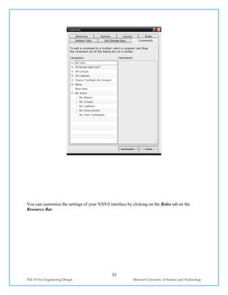
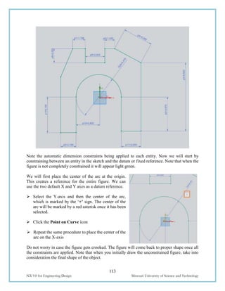
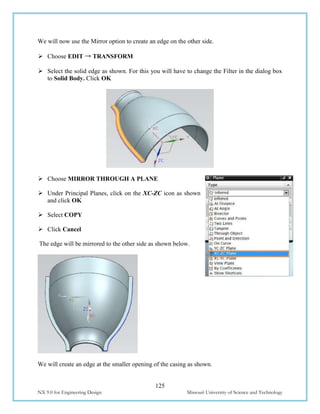
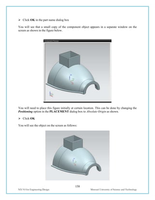
Choose FEEDS AND SPEEDS to enter the feed and speed
parameters
Speed:
Speed normally specifies the rpm of the spindle (spindle
speed). However, technically the speed refers to the cutting
speed of the tool (surface speed). It is the linear velocity of
the cutting tip of the cutter. The relative parameters
affecting this linear speed are rpm of the spindle and the
diameter of the cutter (effective diameter).
Enter the Spindle Speed value as 4500 rpm
For the Surface Speed and the Feed per Tooth, you should enter the recommended values given
by the manufacturers of the cutter [for this example click on the calculator button near spindle
speed]. By entering these values, the software will automatically calculate the cutting feed rate
and spindle speed. You can also enter your own values for feed rates and spindle speeds.
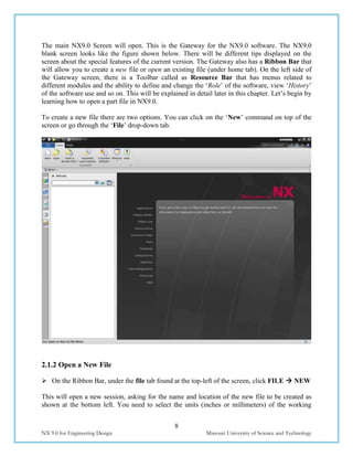
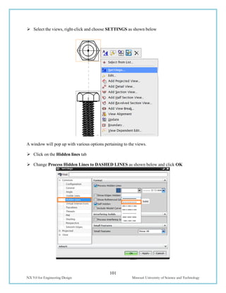
Feeds:
There are many feeds involved in a single program. The
most important is the Cutting feed. This is the feed at
which, the tool will be in engagement with the raw work-
piece and actually cutting the material off the work-piece. It
is the relative linear velocity, at which the cutter moves with
respect to the job.
The other feeds are optional. Some machine control systems
use their default retracts and traverse feed. In those cases,
even if you do not enter the values of other feeds, there
would not be any problems. Some control systems may look
for these feed rates from the program. It can be slightly less
than the machine’s maximum feed rate.
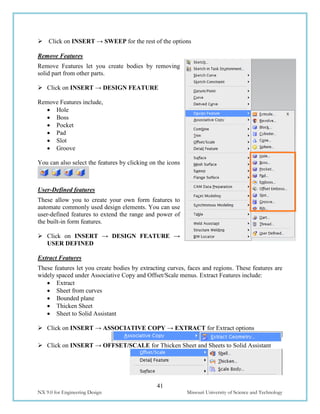
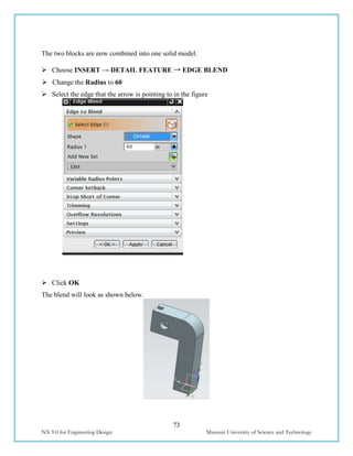
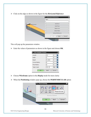
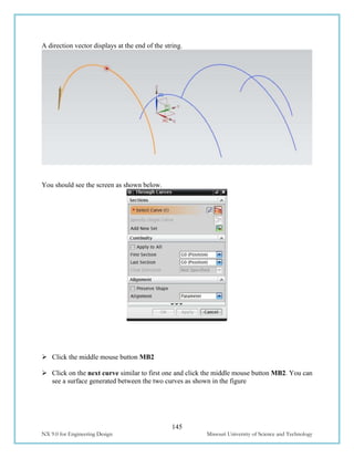
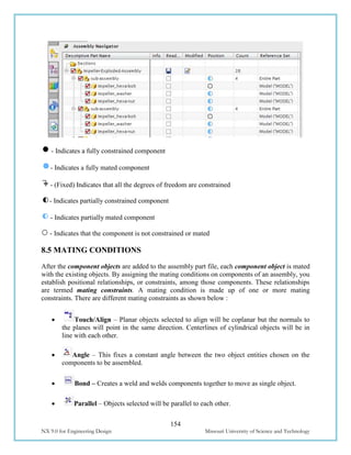
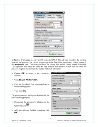
For this exercise, enter the values as shown in the figure.
Make sure to enter the Cut value as 1200 mmpm.
Click OK](https://image.slidesharecdn.com/nx9-160608102546/85/NX9-for-Engineering-Design-218-320.jpg)


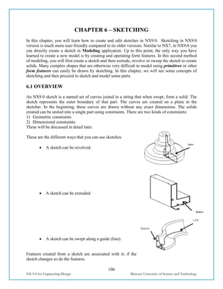
![Caterpillar Diesel Engine Control Systems [PDF, ENG, 588 KB].pdf](https://cdn.slidesharecdn.com/ss_thumbnails/caterpillardieselenginecontrolsystemspdfeng588kb-220908204320-d8164ccc-thumbnail.jpg?width=640&height=640&fit=bounds)