Download to read offline
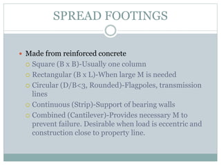
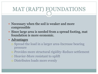


The document provides a detailed overview of shallow and deep foundation designs, including various types of shallow foundations like spread footings and mat foundations, highlighting their construction and applications based on soil conditions. It outlines the calculation methods for bearing capacities, including both gross and net pressures, and differentiates between cohesive and cohesionless soils in foundation design. Additionally, it covers critical factors affecting foundation design, such as groundwater tables and safety factors for various foundation types.


