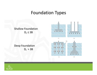
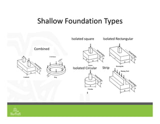
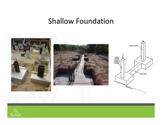
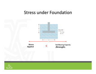
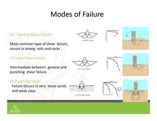
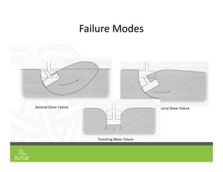
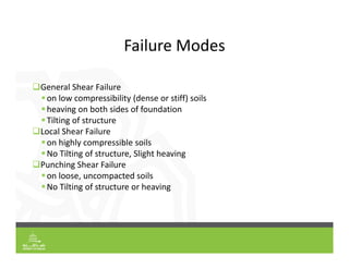
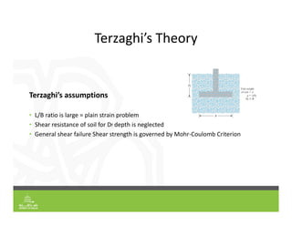
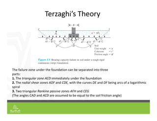
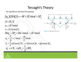
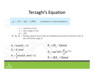
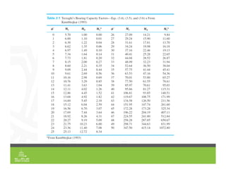
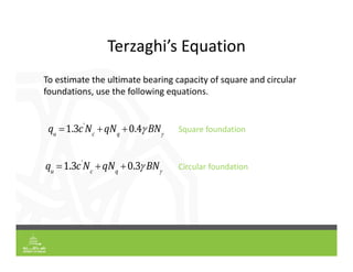
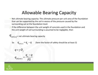
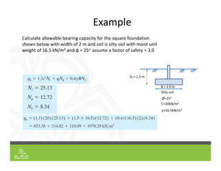
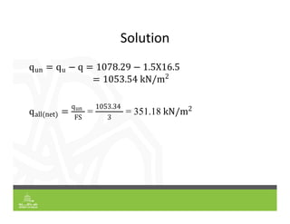
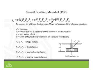
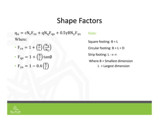
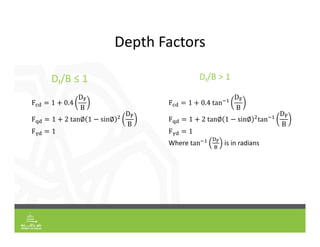
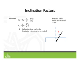
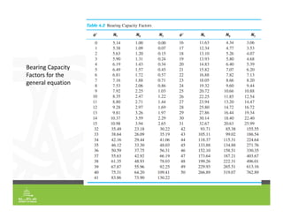
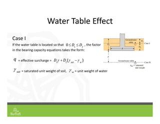
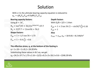
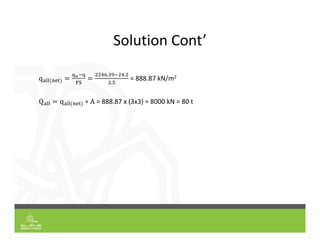
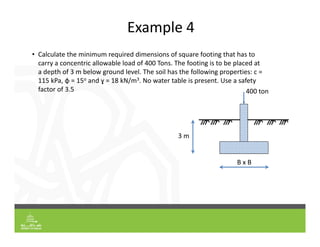
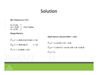
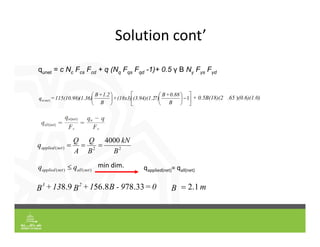
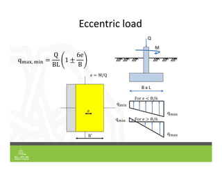
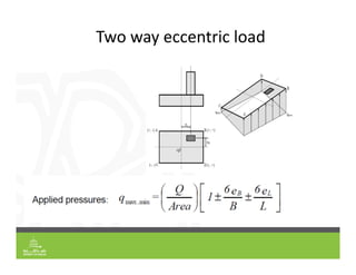
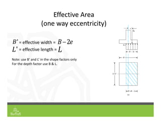
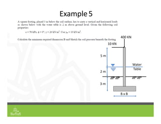
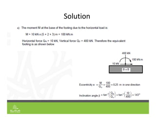
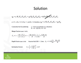
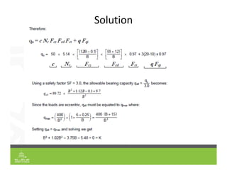
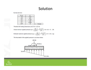
Foundation Engineering
Fall 2020/2021
Soil Bearing Capacity
Mohamed G. Arab, Ph.D.
Assistant Professor
Civil & Environmental Engineering
Agenda
 Shallow Foundation Types
 Soil Bearing Capacity Shallow Foundation
 Shallow Foundation Failure Modes
 Shallow Foundation Bearing Capacity Estimation
Foundation Types
Shallow Foundation
Df ≤ 3B
Deep Foundation
Df > 3B
Shallow Foundation Types
Strip
Isolated square
Combined
Isolated Rectangular
Isolated Circular
Role of Foundation
Stresses !!!!
σ = P/A
Shallow Foundation
Shallow Foundation Construction
Stress under Foundation
≤
Gross Applied Stress
𝒒𝒈𝒓𝒐𝒔𝒔
𝑷 𝜸𝒇𝒊𝒍𝒍∗𝒉𝒇 𝑾𝒇
𝑨
P
q
P B
L
𝜸𝒇𝒊𝒍𝒍
𝒉𝒇
𝑾𝒇= weight of the foundation
𝒒𝒈𝒓𝒐𝒔𝒔
𝑷 𝜸𝒇𝒊𝒍𝒍∗𝒉𝒇 𝜸𝑹𝑪 ∗𝒕𝒓𝒄
𝑨
𝒕𝒓𝒄
Net applied stress
P B
L
q
𝜸𝒇𝒊𝒍𝒍
𝒉𝒇
𝒕𝒓𝒄
𝒒𝒏𝒆𝒕 𝒂𝒂𝒑𝒍𝒊𝒆𝒅
𝑷 𝜸𝒇𝒊𝒍𝒍∗𝒉𝒇 𝑾𝒇 𝑾𝒔
𝑨
𝒒𝒏𝒆𝒕 𝒂𝒑𝒑𝒍𝒊𝒆𝒅
𝑷 𝜸𝒇𝒊𝒍𝒍∗𝒉𝒇 𝜸𝑹𝑪 𝜸𝒔 ∗𝒕𝒓𝒄
𝑨
𝑾𝒇= weight of the foundation
𝑾𝒔= weight of the soil replaced by Foundation
Modes of Failure
(1) General Shear Failure:
Most common type of shear failure;
occurs in strong soils and rocks
(2) Local Shear Failure:
Intermediate between general and
punching shear failure
(3) Punching Shear:
Failure Occurs in very loose sands
and weak clays
Failure Modes
General Shear Failure Local Shear Failure
Punching Shear Failure
Failure Modes
General Shear Failure
on low compressibility (dense or stiff) soils
heaving on both sides of foundation
Tilting of structure
Local Shear Failure
on highly compressible soils
No Tilting of structure, Slight heaving
Punching Shear Failure
on loose, uncompacted soils
No Tilting of structure or heaving
Terzaghi’s Theory
Terzaghi’s assumptions
• L/B ratio is large = plain strain problem
• Shear resistance of soil for Df depth is neglected
• General shear failure Shear strength is governed by Mohr‐Coulomb Criterion
Terzaghi’s Theory
The failure zone under the foundation can be separated into three
parts:
1. The triangular zone ACD immediately under the foundation
2. The radial shear zones ADF and CDE, with the curves DE and DF being arcs of a logarithmic
spiral
3. Two triangular Rankine passive zones AFH and CEG
(The angles CAD and ACD are assumed to be equal to the soil friction angle)
Terzaghi’s Theory
For equilibrium we have the equation
(qu
)(2b)(1) W 2Csin'
2Pp
b  B /2
 b2
tan'
W=
c'
b/(cos')
C=
2bqu
2Pp
2bc'
tan'
 b2
tan'
' 2 ' ' '
1
( tan ) ( tan ) ( tan )
2

   
  
p c q
P b K c b K q b K
qu
 c'
Nc
qNq

1
2
 BN
qu

Pp
b
c'
tan'

 b
2
tan'
Terzaghi’s Equation
Nc
 tan'
(Kc
1)
Nq
 Kq
tan'
N

1
2
tan'
(K
tan'
1)
Nq
 tan2
(45
'
2
)e tan'
Nc
(Nq
1)cot'
N
 2(Nq
1)tan'
Terzaghi’s Equation
 To estimate the ultimate bearing capacity of square and circular
foundations, use the following equations.
Square foundation
Circular foundation
qu
1.3c'
Nc
qNq
0.4 BN
qu
1.3c'
Nc
qNq
0.3 BN
Allowable Bearing Capacity
• Net ultimate bearing capacity: The ultimate pressure per unit area of the foundation
that can be supported by the soil in excess of the pressure caused by the
surrounding soil at the foundation level.
• If the difference between the unit weight of concrete used in the foundation and
the unit weight of soil surrounding is assumed to be negligible, then
= net ultimate bearing capacity
So (here the factor of safety should be at least 3)
qnet(u)
 qu
q
qnet(u)
q  Df
qall(net )

qu
q
FS
Example
Ø=25o
Silty soil
Df = 1.5 m
C=20kN/m2
γ=16.5kN/m3
Calculate allowable bearing capacity for the square foundation
shown below with width of 2 m and soil is silty soil with moist unit
weight of 16.5 kN/m3 and φ = 25o assume a factor of safety = 3.0
B= 2.0 m
Solution
un u
2
all net
qun
FS
=
1053.34
3
= 351.18 2
 To account for all those shortcomings, Meyerhof suggested the following equation:
c‘ = cohesion
q = effective stress at the lever of the bottom of the foundation
γ = unit weight of soil
B = width of foundation (= diameter for a circular foundation)
 = shape factors

 = depth factors

 = load inclination factors
 = bearing capacity factors
General Equation, Meyerhof (1963)
qu
 c'
Nc
Fcs
Fcd
Fci
qNq
Fqs
Fqd
Fqi

1
2
 BN
F s
F d
F i
Fcs
,Fqs
,F s
Fcd
,Fqd
,F d
Fci
,Fqi
,F i
Nc
,Nq
,N
Shape Factors
q cN F qN F 0.5γBN F
Where:
• F 1
• F 1 tan∅
• F 1 0.4
Note:
Square footing: B = L
Circular footing: B = L = D
Strip footing: L  
Where B = Smallest dimension
L = Largest dimension
Depth Factors
Df/B ≤ 1 Df/B > 1
F 1 0.4
D
B
F 1 2 tan∅ 1 sin∅
D
B
F 1
F 1 0.4 tan
D
B
F 1 2 tan∅ 1 sin∅ tan
D
B
F 1
Where tan is in radians
Inclination Factors
β
Bearing Capacity
Factors for the
general equation
Water Table Effect
Case I
If the water table is located so that , the factor
in the bearing capacity equations takes the form:
= effective surcharge =
= saturated unit weight of soil, = unit weight of water
0 D1
 Df
q D1
 D2
( sat
 w
)
 sat  w
Water Table Effect
 Case II
 For a water table located so that ,
 In this case, the factor in the last term of the bearing capacity equations must be
replaced by 𝛾
 𝛾 𝛾 𝛾 𝛾
 where, 𝛾𝑠𝑢𝑏 𝛾𝑠𝑎𝑡 ‐ 𝛾𝑤
𝛾 is the unit weight at the foundation level
0 d  B q Df
Example 3
• A square footing 3m x 3m carries a vertical load Q and is constructed on a
sandy soil. The depth of the footing below ground level is 2 m and water
table is present at 1 m below the surface. The soil has the following
properties: c = 0, φ = 36°, ɣmoist = 16 kN/m3 and ɣsat = 18 kN/m3. Using a
safety factor of 2.5, calculate the maximum allowable load the footing can
carry.
1 m
1 m
3 m
3 m
Solution
With c= 0, the ultimate bearing capacity equation is reduced to
q qN F F +0.5γBN F F
Bearing capacity factors:
Using ∅ 36°
,
N tan 45 36/2 e =37.7
N 2 37.7 1 𝑡𝑎𝑛36 56.3
Shape Factors:
F 1 1/1 tan 36 = 1.73
F 1 0.4 = 0.6
Depth Factors
With Df/B = 2/3 < 1 then
F 1 2 tan 36 1 sin36 =1.16
F 1
Also
𝛾 𝛾 ‐𝛾 = 18‐9.81 = 8.2 kN/m3
The effective stress, q, at the bottom of the footing is
q = 1 x 16 + 1 x 8.2 = 24.20 kPa
Substituting these values in B.C eq. we get
qu= 24.2 x 37.7 x 1.73 x 1.16 + (1/2) x 8.2 x 3 x 56.3 x 0.6 = 2246.39 kPa
Solution Cont’
q
. .
.
= 888.87 kN/m2
Q q ∗ A = 888.87 x (3x3) = 8000 kN = 80 t
Example 4
• Calculate the minimum required dimensions of square footing that has to
carry a concentric allowable load of 400 Tons. The footing is to be placed at
a depth of 3 m below ground level. The soil has the following properties: c =
115 kPa, φ = 15o and ɣ = 18 kN/m3. No water table is present. Use a safety
factor of 3.5
3 m
B x B
400 ton
Solution
Solution cont’



















1
)
(
B
0.88
+
B
7)
(3.94)(1.2
(18x3)
+
B
1.2
+
B
(1.36)
115(10.98)
=
q net
u
(0.6)(1.0)
.65
0.5B(18)(2
+ )
qunet = c Nc Fcs Fcd + q (Nq Fqs Fqd -1)+ 0.5 γ B Nγ Fγs Fγd
0
=
9
-
B
1
+
B
13
+
B
2
3
33
.
78
8
.
56
9
.
8
2
2
)
(
4000
B
kN
B
Q
A
Q
q net
applied 


)
(
)
( net
all
net
applied q
q 
m
B 1
.
2

min dim. qapplied(net)= qall(net)
Eccentric load
q ,
Q
BL
1
6e
B
B x L
Q
M
q
q
For e B/6
q
q For e B/6
Q
e
e M/Q
B′
Two way eccentric load
Effective Area
(one way eccentricity)
= effective width =
= effective length =
B 2e
L' L
B'
Note: use B’ and L’ in the shape factors only
For the depth factor use B & L.
Example5
Water
Table
400 KN
10 KN
5 m
2 m
3 m
B x B
Solution
Solution
Solution
Solution
Thank you
46
Mohamed G. Arab, Ph.D.
Assistant Professor,
Engineering College, Civil & Environmental Engineering Dept.

Lecture5-Chapter4_Soil_Bearing Capacity_fall21-nf(1) (2).pdf

  • 1.
    Foundation Engineering Fall 2020/2021 SoilBearing Capacity Mohamed G. Arab, Ph.D. Assistant Professor Civil & Environmental Engineering
  • 2.
    Agenda  Shallow FoundationTypes  Soil Bearing Capacity Shallow Foundation  Shallow Foundation Failure Modes  Shallow Foundation Bearing Capacity Estimation
  • 3.
    Foundation Types Shallow Foundation Df≤ 3B Deep Foundation Df > 3B
  • 4.
    Shallow Foundation Types Strip Isolatedsquare Combined Isolated Rectangular Isolated Circular
  • 5.
  • 6.
  • 7.
  • 8.
  • 9.
    Gross Applied Stress 𝒒𝒈𝒓𝒐𝒔𝒔 𝑷𝜸𝒇𝒊𝒍𝒍∗𝒉𝒇 𝑾𝒇 𝑨 P q P B L 𝜸𝒇𝒊𝒍𝒍 𝒉𝒇 𝑾𝒇= weight of the foundation 𝒒𝒈𝒓𝒐𝒔𝒔 𝑷 𝜸𝒇𝒊𝒍𝒍∗𝒉𝒇 𝜸𝑹𝑪 ∗𝒕𝒓𝒄 𝑨 𝒕𝒓𝒄
  • 10.
    Net applied stress PB L q 𝜸𝒇𝒊𝒍𝒍 𝒉𝒇 𝒕𝒓𝒄 𝒒𝒏𝒆𝒕 𝒂𝒂𝒑𝒍𝒊𝒆𝒅 𝑷 𝜸𝒇𝒊𝒍𝒍∗𝒉𝒇 𝑾𝒇 𝑾𝒔 𝑨 𝒒𝒏𝒆𝒕 𝒂𝒑𝒑𝒍𝒊𝒆𝒅 𝑷 𝜸𝒇𝒊𝒍𝒍∗𝒉𝒇 𝜸𝑹𝑪 𝜸𝒔 ∗𝒕𝒓𝒄 𝑨 𝑾𝒇= weight of the foundation 𝑾𝒔= weight of the soil replaced by Foundation
  • 11.
    Modes of Failure (1)General Shear Failure: Most common type of shear failure; occurs in strong soils and rocks (2) Local Shear Failure: Intermediate between general and punching shear failure (3) Punching Shear: Failure Occurs in very loose sands and weak clays
  • 12.
    Failure Modes General ShearFailure Local Shear Failure Punching Shear Failure
  • 13.
    Failure Modes General ShearFailure on low compressibility (dense or stiff) soils heaving on both sides of foundation Tilting of structure Local Shear Failure on highly compressible soils No Tilting of structure, Slight heaving Punching Shear Failure on loose, uncompacted soils No Tilting of structure or heaving
  • 14.
    Terzaghi’s Theory Terzaghi’s assumptions •L/B ratio is large = plain strain problem • Shear resistance of soil for Df depth is neglected • General shear failure Shear strength is governed by Mohr‐Coulomb Criterion
  • 15.
    Terzaghi’s Theory The failurezone under the foundation can be separated into three parts: 1. The triangular zone ACD immediately under the foundation 2. The radial shear zones ADF and CDE, with the curves DE and DF being arcs of a logarithmic spiral 3. Two triangular Rankine passive zones AFH and CEG (The angles CAD and ACD are assumed to be equal to the soil friction angle)
  • 16.
    Terzaghi’s Theory For equilibriumwe have the equation (qu )(2b)(1) W 2Csin' 2Pp b  B /2  b2 tan' W= c' b/(cos') C= 2bqu 2Pp 2bc' tan'  b2 tan' ' 2 ' ' ' 1 ( tan ) ( tan ) ( tan ) 2         p c q P b K c b K q b K qu  c' Nc qNq  1 2  BN qu  Pp b c' tan'   b 2 tan'
  • 17.
    Terzaghi’s Equation Nc  tan' (Kc 1) Nq Kq tan' N  1 2 tan' (K tan' 1) Nq  tan2 (45 ' 2 )e tan' Nc (Nq 1)cot' N  2(Nq 1)tan'
  • 19.
    Terzaghi’s Equation  Toestimate the ultimate bearing capacity of square and circular foundations, use the following equations. Square foundation Circular foundation qu 1.3c' Nc qNq 0.4 BN qu 1.3c' Nc qNq 0.3 BN
  • 20.
    Allowable Bearing Capacity •Net ultimate bearing capacity: The ultimate pressure per unit area of the foundation that can be supported by the soil in excess of the pressure caused by the surrounding soil at the foundation level. • If the difference between the unit weight of concrete used in the foundation and the unit weight of soil surrounding is assumed to be negligible, then = net ultimate bearing capacity So (here the factor of safety should be at least 3) qnet(u)  qu q qnet(u) q  Df qall(net )  qu q FS
  • 21.
    Example Ø=25o Silty soil Df =1.5 m C=20kN/m2 γ=16.5kN/m3 Calculate allowable bearing capacity for the square foundation shown below with width of 2 m and soil is silty soil with moist unit weight of 16.5 kN/m3 and φ = 25o assume a factor of safety = 3.0 B= 2.0 m
  • 22.
  • 23.
     To accountfor all those shortcomings, Meyerhof suggested the following equation: c‘ = cohesion q = effective stress at the lever of the bottom of the foundation γ = unit weight of soil B = width of foundation (= diameter for a circular foundation)  = shape factors   = depth factors   = load inclination factors  = bearing capacity factors General Equation, Meyerhof (1963) qu  c' Nc Fcs Fcd Fci qNq Fqs Fqd Fqi  1 2  BN F s F d F i Fcs ,Fqs ,F s Fcd ,Fqd ,F d Fci ,Fqi ,F i Nc ,Nq ,N
  • 24.
    Shape Factors q cNF qN F 0.5γBN F Where: • F 1 • F 1 tan∅ • F 1 0.4 Note: Square footing: B = L Circular footing: B = L = D Strip footing: L   Where B = Smallest dimension L = Largest dimension
  • 25.
    Depth Factors Df/B ≤1 Df/B > 1 F 1 0.4 D B F 1 2 tan∅ 1 sin∅ D B F 1 F 1 0.4 tan D B F 1 2 tan∅ 1 sin∅ tan D B F 1 Where tan is in radians
  • 26.
  • 27.
    Bearing Capacity Factors forthe general equation
  • 28.
    Water Table Effect CaseI If the water table is located so that , the factor in the bearing capacity equations takes the form: = effective surcharge = = saturated unit weight of soil, = unit weight of water 0 D1  Df q D1  D2 ( sat  w )  sat  w
  • 29.
    Water Table Effect Case II  For a water table located so that ,  In this case, the factor in the last term of the bearing capacity equations must be replaced by 𝛾  𝛾 𝛾 𝛾 𝛾  where, 𝛾𝑠𝑢𝑏 𝛾𝑠𝑎𝑡 ‐ 𝛾𝑤 𝛾 is the unit weight at the foundation level 0 d  B q Df
  • 32.
    Example 3 • Asquare footing 3m x 3m carries a vertical load Q and is constructed on a sandy soil. The depth of the footing below ground level is 2 m and water table is present at 1 m below the surface. The soil has the following properties: c = 0, φ = 36°, ɣmoist = 16 kN/m3 and ɣsat = 18 kN/m3. Using a safety factor of 2.5, calculate the maximum allowable load the footing can carry. 1 m 1 m 3 m 3 m
  • 33.
    Solution With c= 0,the ultimate bearing capacity equation is reduced to q qN F F +0.5γBN F F Bearing capacity factors: Using ∅ 36° , N tan 45 36/2 e =37.7 N 2 37.7 1 𝑡𝑎𝑛36 56.3 Shape Factors: F 1 1/1 tan 36 = 1.73 F 1 0.4 = 0.6 Depth Factors With Df/B = 2/3 < 1 then F 1 2 tan 36 1 sin36 =1.16 F 1 Also 𝛾 𝛾 ‐𝛾 = 18‐9.81 = 8.2 kN/m3 The effective stress, q, at the bottom of the footing is q = 1 x 16 + 1 x 8.2 = 24.20 kPa Substituting these values in B.C eq. we get qu= 24.2 x 37.7 x 1.73 x 1.16 + (1/2) x 8.2 x 3 x 56.3 x 0.6 = 2246.39 kPa
  • 34.
    Solution Cont’ q . . . =888.87 kN/m2 Q q ∗ A = 888.87 x (3x3) = 8000 kN = 80 t
  • 35.
    Example 4 • Calculatethe minimum required dimensions of square footing that has to carry a concentric allowable load of 400 Tons. The footing is to be placed at a depth of 3 m below ground level. The soil has the following properties: c = 115 kPa, φ = 15o and ɣ = 18 kN/m3. No water table is present. Use a safety factor of 3.5 3 m B x B 400 ton
  • 36.
  • 37.
    Solution cont’                    1 ) ( B 0.88 + B 7) (3.94)(1.2 (18x3) + B 1.2 + B (1.36) 115(10.98) = q net u (0.6)(1.0) .65 0.5B(18)(2 +) qunet = c Nc Fcs Fcd + q (Nq Fqs Fqd -1)+ 0.5 γ B Nγ Fγs Fγd 0 = 9 - B 1 + B 13 + B 2 3 33 . 78 8 . 56 9 . 8 2 2 ) ( 4000 B kN B Q A Q q net applied    ) ( ) ( net all net applied q q  m B 1 . 2  min dim. qapplied(net)= qall(net)
  • 38.
    Eccentric load q , Q BL 1 6e B Bx L Q M q q For e B/6 q q For e B/6 Q e e M/Q B′
  • 39.
  • 40.
    Effective Area (one wayeccentricity) = effective width = = effective length = B 2e L' L B' Note: use B’ and L’ in the shape factors only For the depth factor use B & L.
  • 41.
  • 42.
  • 43.
  • 44.
  • 45.
  • 46.
    Thank you 46 Mohamed G.Arab, Ph.D. Assistant Professor, Engineering College, Civil & Environmental Engineering Dept.