Download to read offline


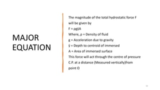
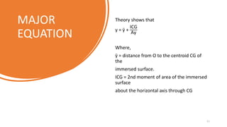
![MAJOR
EQUATION
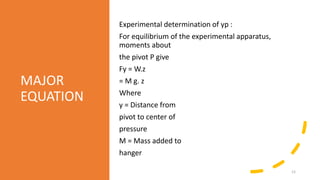
z = Distance from pivot to hanger
Therefore
y =
Mgz
F
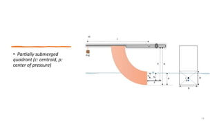
But y = yp + r - y1 [ full submerged ]
y = yp = r + y1 [ partially submerged ]
Therefore
yp = y - (r - y1) [ fully submerged ]
yp = y - (r + y1) [ partially submerged ]
Where
r = Distance from pivot to top of
rectangular surface
y1 = Distance from water surface to top of
rectangular surface
In Fig
y2 = Distance from water surface to
bottom of rectangular surface
Fully submerged quadrant (c: centroid, p: center of pressure)
13](https://image.slidesharecdn.com/fluidsessinalpresentation-210823120121/85/Fluid-sessinal-presentation-13-320.jpg)

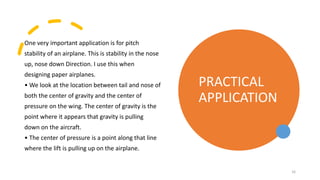


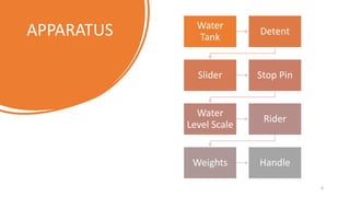
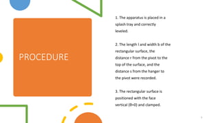
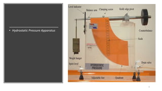
This presentation discusses the center of pressure in hydrostatic systems. It is introduced by Sumaiya Tabassum from the Department of Civil Engineering at Stamford University Bangladesh. The presentation is supervised by six individuals and presented by two others. The document defines the center of pressure as the point where the total sum of a pressure field acts on a body, causing an equivalent force. It then describes the experimental apparatus and procedures for determining the center of pressure of partially and fully submerged surfaces. Major equations are provided relating the center of pressure to factors like density, depth, and mass. Practical applications are mentioned in aircraft aerodynamics and stability.


![Chapter 3 static forces on surfaces [compatibility mode]](https://cdn.slidesharecdn.com/ss_thumbnails/chapter-3-static-forces-on-surfaces-compatibility-mode-160214035852-thumbnail.jpg?width=640&height=640&fit=bounds)


