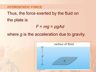
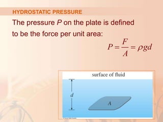
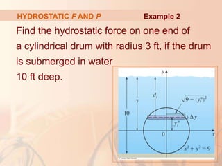
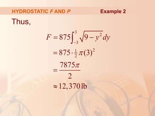
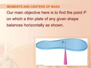
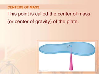
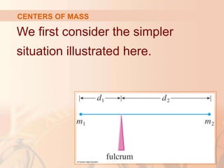
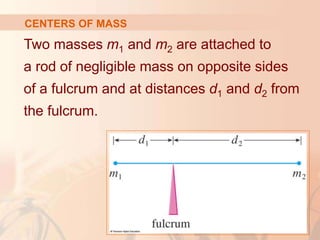
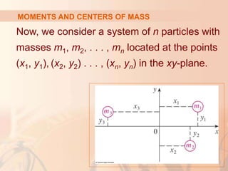
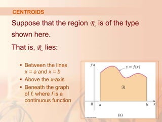
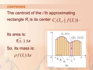
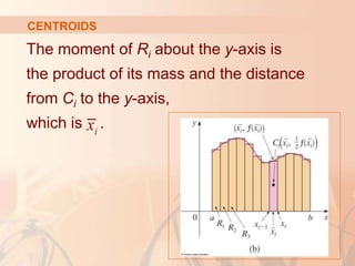
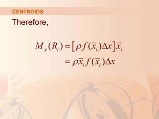
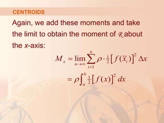
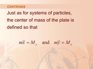
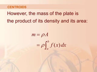
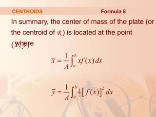
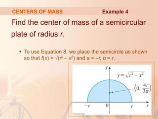
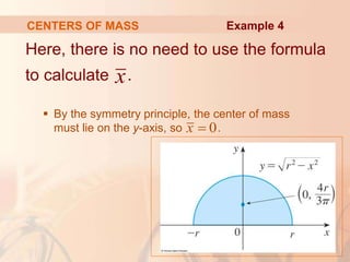
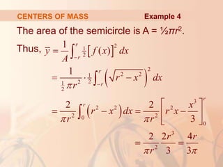
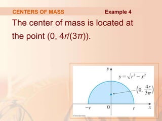
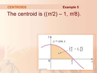
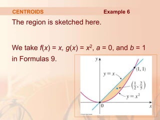
This document discusses applications of integral calculus to physics and engineering problems involving force, pressure, and centers of mass. It provides examples of using integrals to calculate the hydrostatic force on structures like dams and cylinders submerged in water. It also explains how to find the center of mass of an object or system of point masses by taking moments about axes and dividing by total mass. Formulas are given for calculating hydrostatic pressure, moments, and centers of mass in one and two dimensions.


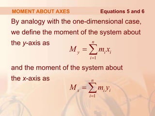
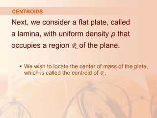
![The depth of the water is 16 m.
So, we divide the interval [0, 16] into subintervals
of equal length with endpoints xi.
We choose
xi* [xi–1, xi].
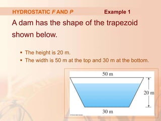
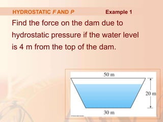
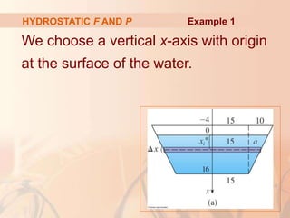
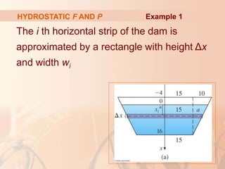
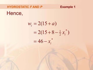
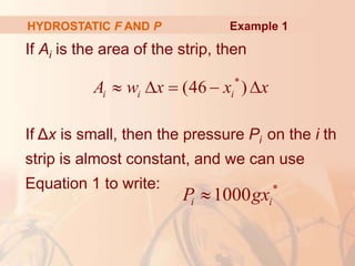
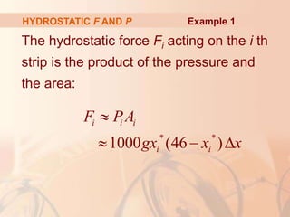
HYDROSTATIC F AND P Example 1
](https://image.slidesharecdn.com/chap8sec3-220829135656-7db0b0cd/85/Chap8_Sec3-ppt-17-320.jpg)
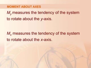
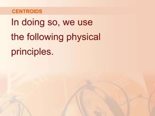


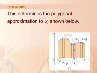
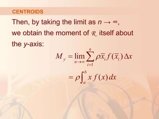
![We divide the interval [a, b] into n subintervals
with endpoints x0, x1, . . . , xn and equal width
∆x.
We choose the
sample point xi
* to
be the midpoint
of the i th
subinterval.
That is,
= (xi–1 + xi)/2
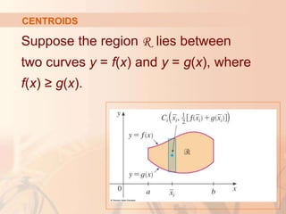
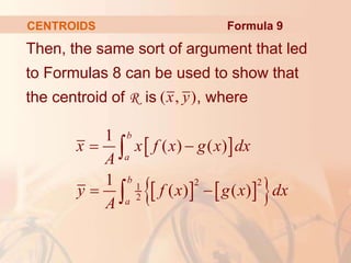
CENTROIDS
i
x
i
x](https://image.slidesharecdn.com/chap8sec3-220829135656-7db0b0cd/85/Chap8_Sec3-ppt-63-320.jpg)


![Chapter 3 static forces on surfaces [compatibility mode]](https://cdn.slidesharecdn.com/ss_thumbnails/chapter-3-static-forces-on-surfaces-compatibility-mode-160214035852-thumbnail.jpg?width=640&height=640&fit=bounds)


