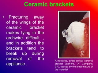
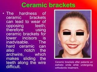
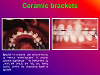
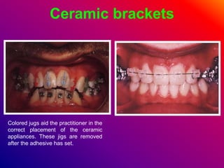
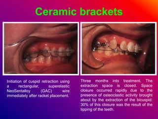
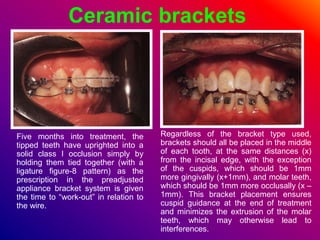
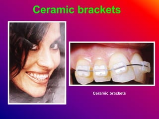
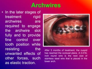
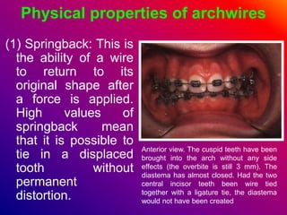
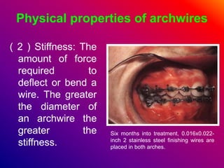
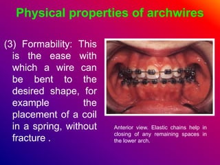
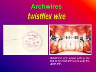
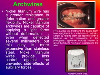
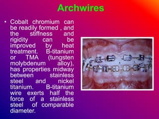
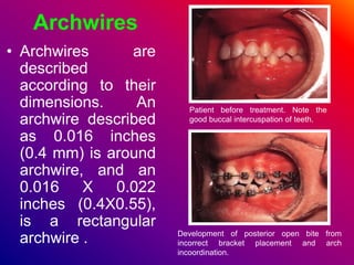
2. Ceramic brackets
⢠Fracturing away
of the wings of the
ceramic bracket
makes tying in the
archwire difficult ,
and in addition the
brackets tend to
break up during
removal of the
appliance .
A fractured, single-crystal ceramic
bracket (star-fire, âAâ Company,
CA), caused by the brittle nature of
the material.
3. Ceramic brackets
⢠The hardness of
ceramic brackets
can lead to wear of
opposing teeth;
therefore using
ceramic brackets for
lower incisors is
inadvisable. The
hard ceramic can
also notch the
archwire, which
makes sliding the
teeth along the wire
difficult.
Ceramic brackets after patients an
esthetic smile while undergoing
orthodontic treatment.
4. Ceramic brackets
Special instruments are recommended
by various manufacturers to debond
ceramic appliances. This instrument, by
Unitek/3M should be fully and firmly
seated before the debonding force is
applied.
5. Ceramic brackets
Colored jugs aid the practitioner in the
correct placement of the ceramic
appliances. These jigs are removed
after the adhesive has set.
6. Ceramic brackets
Initiation of cuspid retraction using
a rectangular, superelastic
NeoSentalloy (GAC) wire
immediately after racket placement.
Three months into treatment. The
extraction space is closed. Space
closure occurred rapidly due to the
presence of osteoclastic activity brought
about by the extraction of the bicuspid:
30% of this closure was the result of the
tipping of the teeth.
7. Ceramic brackets
Five months into treatment, the
tipped teeth have uprighted into a
solid class I occlusion simply by
holding them tied together (with a
ligature figure-8 pattern) as the
prescription in the preadjusted
appliance bracket system is given
the time to âwork-outâ in relation to
the wire.
Regardless of the bracket type used,
brackets should all be placed in the middle
of each tooth, at the same distances (x)
from the incisal edge, with the exception
of the cuspids, which should be 1mm
more gingivally (x+1mm), and molar teeth,
which should be 1mm more occlusally (x â
1mm). This bracket placement ensures
cuspid guidance at the end of treatment
and minimizes the extrusion of the molar
teeth, which may otherwise lead to
interferences.
9. Ceramic brackets
The rectangular superelastic
NeoSentalloy (GAC) archwire provides
the greatest archwire flexibility
available today, as well as control of
torque from the onset of treatment.
The same patient after 1 month. Note
that the cuspid has almost reached the
occlusal plane (5 mm movement). No
patient discomfort was expressed.
10. Orthodontic adhesives
⢠The most popular
cement for
cementing bands is
glass ionomer
mainly because of
its fluoride
releasing potential
and affinity to
stainless steel and
enamel .
Glass ionomer cement.
11. Orthodontic adhesives
⢠Glass ionomer
can also be used
for retaining
bonded
attachments, but
unfortunately the
bracket failure
rate with this
material is greater
than that with
composite .
Glass ionomer cement.
12. Orthodontic adhesives
⢠Use of the acid-
etch technique with
a composite
produces clinically
acceptable bonded
attachment failure
rates of the order
of 5 â 10 per cent
for both self and
light cured
materials.
After isolation with cheek retractors (for
both arches) or cotton rolls (for single-
tooth procedures), the teeth are pumiced
and adequately rinsed, followed by acid
etching with a disposable brush for 15
seconds.
13. Orthodontic adhesives
⢠Although conventional
self cured composite
can be used for
bonding, a
modification has been
manufactured
specially for
orthodontics to
circumvent the
problem of air bubbles
which would
compromise bond
retention .
Thorough rinsing and drying are
absolutely necessary in order to
obtain the chalky-white etched tooth
surface that allows for a good bond.
At this point, the tooth is ready to
receive the bracket.
14. Orthodontic adhesives
⢠No â mix orthodontic
composites comprise
an activator which is
painted onto both the
bracket base and the
tooth surface ( after
etching) . Following this
, a small amount of the
composite itself is
applied to the bracket
which is then placed on
the tooth surface under
pressure .
Most adhesives come with two parts: a
liquid form and a paste form.
15. Orthodontic adhesives
⢠Squeezing the
sandwich of
composite and
catalyst into a thin
layer mixes the
two components,
and the material
usually sets within
few minutes .
The liquid part is applied onto the
tooth surface with a brush by the
clinician.
16. Orthodontic adhesives
⢠Whatever material
is used , any
excess should be
cleared from the
perimeter of the
bracket before the
final set to reduce
plaque retention
around the bonded
attachment .
The paste is placed onto the bracket
base by the chairside assistant.
17. Orthodontic adhesives
The bracket is then placed on the
center of the tooth with a special
holding plier or even a pair of cotton
pliers.
The clinician then aligns the
bracket along the long axis of the
tooth at a specific distance from the
incisal edge.
18. Orthodontic adhesives
This is more easily done for the twin
and deltoid brackets with the perio
probe, due to the convenient shape of
these appliance.
At the end, as a final check, the
bracket is checked with a mouth mirror
to ensure that it is aligned properly.
22. Auxiliaries
⢠Very small elastic bands,
often described as
elastomeric modules, or wire
ligatures are used to secure
the archwire into the
archwire slot. Elastic
modules are quicker to
place and are usually more
comfortable for the patient,
but wire ligatures are often
preferred, particularly in the
later stages of treatment, as
they can be tightened to
maximize contact between
the wire and the bracket. Intra-oral elastics.
24. Intraoral elastics
Cut from pure surgical latex tubing
for the highest elasticity and
resistance to oral liquid. All
packages indicate the diameter size
and the elastic pull which comes
into force when the elastic is
stretched to the three times its
diameter.
All packages are differently color
coded for easy reference.
Box of 10 bags, 100 elastics each
bag.
Intraoral colored elastic
High elasticity and fatigue
resistance
Extraoral elastics
Cut from pure surgical latex.
Prepackaged in bags of 100
Extraoral elastics kit
Assorted box of 10 bags, 1 each diameter and
pull force, 100 elastics each bag.
26. Power chain
Elastic chains kit
K6429-93 transparent
K6469-93 grey
K6489-93 Ivory
Prepackaged with 6 spools of
assorted elastic chains, three
short, two closed and one long,
conveniently organized on a
plexyglass rack. Available in
three colors.
27. Auxiliaries
⢠Intra â oral ( latex )
elastics for traction
are commonly
available in 2 oz
and 3.5 oz
strengths and a
variety of sizes ,
ranging from 1/8
inch to ž inch .For
most purposes they
should be changed
every day.
28. Auxiliaries
⢠Palatal or lingual
arches: they can be
used to reinforce
anchorage or to
achieve expansion
(the quadhelix
appliance). Some
designs have the
additional advantage
of being removable,
thus facilitating
adjustment .
Brackets bonded to palatally placed
canines, allowing the application of
orthodontic forces to the teeth.
The circle hook in the sectional buccal
archwire acts as a guide for the elastic thread
and ensures the correct application of the
force to bring the canine buccally.
29. Auxiliaries
A palatal arch, called a Nance bulb,
which is used to help provide
additional anchorage in the upper
arch by helping to resist forward
movement of the molars.
A proprietary removable quadhelix.
The distal aspect of the arms of the
helix slot into the lingual sheaths (also
shown) which are welded onto the
palatal surface of bands on the upper
molars.
30. Archwires
⢠In the initial stages
of treatment a wire
which is flexible
with good
resistance to
permanent
deformation is
desirable , so that
displaced teeth can
be aligned without
the application of
excessive forces .
A Sentalloy (GAC) round NiTi wire is placed
as the initial archwire in the maxillary arch. A
0.012-inch, round, stainless steel wire is
placed in the lower arch. The upper lateral
incisors and bicuspids were not incorporated
in this alignment phase in order to avoid
unnecessary tipping of these teeth.
32. Archwires
⢠In the later stages of
treatment rigid
archwires are
required to engage
the archwire slot
fully and to provide
fine control over
tooth position while
resisting the
unwanted effects of
other forces, such
as elastic traction.
After 3 months of treatment, the cuspid
has reached the occlusal plane. A 0.016-
inch round wire is the next size of
stainless steel wire that is placed in the
lower arch.
33. Physical properties of archwires
(1) Springback: This is
the ability of a wire
to return to its
original shape after
a force is applied.
High values of
springback mean
that it is possible to
tie in a displaced
tooth without
permanent
distortion.
Anterior view. The cuspid teeth have been
brought into the arch without any side
effects (the overbite is still 3 mm). The
diastema has almost closed. Had the two
central incisor teeth been wire tied
together with a ligature tie, the diastema
would not have been created
34. Physical properties of archwires
( 2 ) Stiffness: The
amount of force
required to
deflect or bend a
wire. The greater
the diameter of
an archwire the
greater the
stiffness.
Six months into treatment, 0.016x0.022-
inch 2 stainless steel finishing wires are
placed in both arches.
35. Physical properties of archwires
(3) Formability: This
is the ease with
which a wire can
be bent to the
desired shape, for
example the
placement of a coil
in a spring, without
fracture .
Anterior view. Elastic chains help in
closing of any remaining spaces in
the lower arch.
36. Physical properties of archwires
(4) Resilience: This
is the stored
energy available
after deflection of
an archwire without
permanent
deformation
(5) Biocompatibility.
Eight months into treatment, a figure-8
configuration of ligature wire (from the left
first molar to the right one) consolidates
and keeps the teeth in contact after
space closure.
37. Physical properties of archwires
(6) Joinability: This is
whether the material
can be soldered or
welded
(7)Frictional
characteristics: If
tooth movement is to
proceed quickly a
wire with low surface
friction is preferable.
Initiation of cuspid retraction using a
rectangular, superelastic NeoSentalloy
(GAC) wire immediately after bracket
placement.
38. Archwires
Properties of some of the more commonly used archwire materials
SS. stainless steel: NiTi, nickel titanium: TMA, β-titanium: CoCr, cobalt chromium.
CoCr wires can be manipulated in the softened state and then heat-treated to
increase resistance to deformation.
SS NiTi TMA CoCr*
Springback Low High Medium Low
Stiffness High Low Medium High
Formability Good Poor Good Good
Resilience Low High Medium Low
Biocompatibility Good ? Good Good
Friction Low Medium High Medium
39. Archwires
⢠The most popular wire is
stainless steel because it is
inexpensive, easily formed and
exhibits good stiffness. Because
of these characteristics,
stainless steel is particularly
useful in the later stages of
treatment. More flexible
stainless steel wire have been
developed which consist of
three or more strands of fine
stainless steel wire twisted or
braided together. There are
known as multistrand or
twistflex wire and they are more
flexible than a solid stainless
steel wire of comparable
diameter. Multistrand wires can
exert too high a force , and be
distorted if tied into a markedly
displaced tooth.
The most popular archwire material is stainless
steel which is available in straight lengths, as a coil
on a spool or pre-formed into archwires.
Three months into treatment. The extraction space is
closed. Space closure occurred rapidly due to the
presence of osteoclastic activity brought about by the
extraction of the bicuspid; 30% of this closure was
the result of the tipping of the teeth.
41. Archwires
⢠Nickel titanium wire has
a greater resistance to
deformation and greater
flexibility. Nickel titanium
archwires are capable of
applying a light force
without deformation ,
even when deflected
several millimeters, but
this alloy is more
expensive than stainless
steel. Nickel titanium
wires provide less
control against the
unwanted side-effects of
auxiliary forces .
Nickel titanium wire.
Five months into treatment, the tipped teeth
have uprighted into a solid class I occlusion
simply by holding them tied together (with a
ligature) as the prescription in the
preadjusted appliance bracket system is
given the time to âwork-outâ in relation to the
wire.
42. Archwires
⢠Cobalt chromium can
be readily formed , and
the stiffness and
rigidity can be
improved by heat
treatment. B-titanium
or TMA (tungsten
molybdenum alloy),
has properties midway
between stainless
steel and nickel
titanium. B-titanium
wire exerts half the
force of a stainless
steel of comparable
diameter.
43. Archwires
⢠Archwires are
described
according to their
dimensions. An
archwire described
as 0.016 inches
(0.4 mm) is around
archwire, and an
0.016 X 0.022
inches (0.4X0.55),
is a rectangular
archwire .
Patient before treatment. Note the
good buccal intercuspation of teeth.
Development of posterior open bite from
incorrect bracket placement and arch
incoordination.
44. Archwires
⢠Archwires are
available in
straight
lengths, as
coils, or as
performed
archwires
which is more
costly to buy
but saves
chairside time.
Patient in fixed appliances during
45. Archwires
⢠There are a wide
variety of archform
shapes ; however ,
regardless of what
design is chosen .
Some adjustment
of the archwire to
match the
pretreatment
archform of the
patient will be
required . The amount of adjustment required to a pre-
formed lower archwire, as taken from the packet,
to ensure that it conforms to the patientâs
pretreatment archform and width.
Incorrect bracket placement, lack of
coordination in the archwires, and lingual
tipping of teeth during space closure led to
the development of this open-bite situation.
46. Ready-made Archwires
Preformed round and rectangular archwires:
Standard preformed. Made out of extra spring
hard wire for higher resiliency. Marked at the
midline, black for upper and red for lower.
Marking pencils for arches, bite
planes, etc.
Standard arches holder
47. Archwires
⢠The force exerted by a
particular archwire
material is given by the
formula :
Where d is the distance
that the spring / wire is
deflected ,r is the
radius of the wire , and
l is the length of the
wire .
Archwire âskewedâ to the left.
48. Ligation of Archwires
The placement of the elastomeric modules (âOâ rings) over the bracket is done
with a hemostat. The module is hooked around one wing and then with the
baseball âhorme-runâ twisting motion, all four rings of the twin bracket are
engaged.
51. Ligation of Archwires
For the hook-up of the elastic chains, the procedure is quite similar: on insertion of
one of the loops, the chain is stretched and the rest is tied in a similar manner.
52. Ligation of Archwires
To secure the archwire in the bracket slot
tightly, a ligature wire-tie is used. It is
placed beneath first the mesial wings of
the bracket and then the distal ones while
sliding along the main archwire. At this
point, the two legs are crossed over,
twisted by hand a few times, and then
securely tightened with a hemostat. The
excess ligature is cut off and the
remaining 3-mm twisted part is placed
beneath the main arch wire.
When removal of a ligature wire-tie is
desired, a ligature-cutter plier may be
used to cut the wire and, without letting
go of it, the ligature the is removed with
the same plier.
54. Metal ligatures for securing the
archwire into the bracket slot.
This patientâs upper archwire has been
tied into place with wire ligatures in the
upper arch and with elastomeric
modules in the lower arch.
55. Archwires
⢠Increasing the
diameter of the
archwire will affect
the force applied to
the teeth.
⢠Increasing the
length or span of
wire between the
brackets will
inversely affect the
applied force . Deactivated coil spring after
significant distal molar movement.
56. Archwires
⢠The distance between the brackets can be
increased by reducing the width of the brackets, but
the interbracket span can also be increased by the
placement of loops in the archwire .
Starting 0.016-inch stainless steel
archwires. A maxillary looped archwire
was used to bring down the canine. A
molar stop preserved arch length. Light (2
oz) class II elastics helped open the bite
and corrected the class II interarch
relationship.
A mandibular preformed looped 0.016-
inch, stainless steel archwire, alleviated
crowding. A âplainâ maxillary 0.016-inch
archwire with molar stops preserved
space for canines.
57. Archwires
⢠Prior to the introduction of the newer more flexible alloys,
multilooped stainless steel arhwires were used in the
initial stages of treatment. Loops are still utilized in
retraction archwires and where a combination of a rigid
archwire (to resist unwanted forces) with localized
flexibility is required .
Lack of space for the second mandibular
premolar Nickel-Titanium wire in a bell
shape curve note the position of the
stops.
Note the space opening amount after 8
weeks with a single activation. The Nickel-
Titanium wire is flat and enough space is
created for the un-erupted premolar.
58. Archwires
⢠When a fixed appliance is first placed a flexible
archwire is advisable to avoid applying excessive
forces to displaced teeth , which can be painful for
the patient and result in bond failure.
The coil spring can be easily reactivated without
taking out the main archwire, simply by compressing
it distally with a sealer and adding the residual
springs from the adjacent interbracjet area. The
clinician should try to avoid cutting the springs in a
way that may impringe on the soft tissue. As soon as
all posterior teeth and the cuspid have been
sequentially brought back with the coil springs, the
four incisor teeth can then be retracted with
elasiomeric chains.
The distal movement of the bicuspid teeth can be
reinforced with a sentalloy (GAC) closed coil spring
that extends from the first molar hook to a hook on
the bicuspid bracket. The stop in the archwire right in
front of the first molar prevents its movement
mesially.
59. Archwires
⢠Either a multistrand
stainless steel archwire or
a preformed nickel titanium
archwire is used to
achieve initial alignment.
Alternatively , loops can be
placed in a stainless steel
archwires, to increase the
span of wire between
brackets and thus increase
flexibility. This approach is
useful if a rigid archwire is
desirable in other areas of
the arch .
60. Archwires
Anterior view. Compare the vertical
activation of more than 7 mm of the
Sentalloy (GAC) round wire in the maxillary
arch to the 0-5 mm of activation of the
0.012-inch stainless steel wire in the
mandibular arch.
Move on from the initial
aligning archwires as soon
as alignment is achieved, as
by virtue of their flexibility
they do not afford much
control of tooth position .
After 1 month of treatmen. The cuspid tooth
has come down 3 mm. A 0.014-inch rounf
wire is placed in the lower arch as the next
step of stainless steel mechanotherapy.
Full bracket engagement should
be achieved before proceeding
to a more rigid archwire. It is
usual to progress through round
archwires of increasing diameter
to achieve progressively better
intra-arch alignment .
61. Archwires
If tooth alignment alone is required, for example in a Class I malocclusion
with rotations, a stiff round archwire which nearly fills the bracket slot will
suffice. Correction of inter-arch relationships and space closure is best
carried out using rectangular wires for apical control. The exact archwire
sequence will depend upon the dimensions of the archwire slot and
operator preference.
Anterior wire. Note that there is a slight
diastema that has opened between the
central incisors as these teeth moved
slightly mesially from the reaction to the
cuspid movement.
After 2 months of treatment. The
initial activation of the upper wire has
brought the cuspids 5mm more
occlusally.
62. Mesiodistal tooth movement
⢠Mesiodistal tooth
movement cab be
achieved by:
(1) Moving teeth with
the archwire by
incorporating loops
into the archwire,
which, when
activated, move a
section of the
archwire and the
attached teeth.
A traction ligature to apply a force
from the molar hook to the archwire.
A sectional archwire to retract /3.
63. Mesiodistal tooth movement
(2) Sliding teeth along the archwire under the influence of
elastic force. A greater force is required to overcome friction
between the bracket and the wire, and therefore places a
greater strain on anchorage. This type of movement is
known as sliding mechanics .
Sliding teeth along the archwire
using a nickel titanium coil spring.
Compressed coil spring to open
space.
64. Mesiodistal movement
⢠Sliding mechanics is
more applicable to
preâadjusted
appliances where a
straight wire is used. In
the edgewise
appliance the first-
second- and third
order bends necessary
in the archwire make
sliding teeth along it
difficult .
After only 5 weeks, on return of the patient for
her first adjustment appointment. the molar
had moved distally more than 4 mm! The
cuspid was still in a class I occlusion and the
overjet was the same as before, thus
emphasizing that the adverse effects of this
system (increase in the overjet, flaring of the
anterior teeth) are kepi to a minimum or that
they do not have the time to express
themselves before the desired distal molar
movement takes place.
65. Adjustment of fixed appliance
⢠Adjustment to the appliance
need to be made on a
regular basis , usually every
four to six weeks. Once
space closure is complete
and incisor position
corrected, a more flexible
fullâsized archwire is tied on
in conjunction with vertical
elastic traction to help
sockâin the buccal
occlusion. In order to
overcome the tendency for
relapse of rotational and
apical movements,
overcorrection should done.
Anterior view. The overbite has
decreased by 1 mm due to the patientâs
slight vertical growth pattern.
66. Fixed appliance system
⢠Preadjusted appliances:
The need for first, second
and third order bends in the
archwire during treatment
is reduced because the
brackets are manufactured
with the slot cut in such a
way that these movements
are built in. Therefore plain
preformed archwires can
be used so that the teeth
are moved progressively
from the very start of
treatment to their ideal
position. Hence they are
also known as the straight
wire appliance.
Upper right canine ovation bracket.
Compond contour base and slot aligment
with reference point on the tooth crown.
67. Pre â adjusted fixed appliances
⢠As individual tooth positions are built into the
bracket , it is necessary to produce a bracket
for each tooth , but the time saved in wire
bending and the superior results achieved
compensate for the cost of brackets .
Difference between preadjusted edgewise (A) and fully adjusted appliances (B).
68. Pre â adjusted fixed appliance
⢠The preâadjusted bracket system will not
eliminate the need for wire bending as only
average values are built into the appliance, and
often additional individual bends need to be
placed in the archwire.
Original Roth Rx appliance (1975) (left) and Andrews standard straight wire
appliance (right).
69. Pre â adjusted fixed appliance
⢠There are many different opinions as to the
correct position of each tooth, the result is several
pre â adjusted systems, all with slightly differing
degrees of torque and tip. Of these the best
known is the Andrewsâ system.
Right side of patientâs mouth with
Ormco/âAâ Co. appliance with Roth
Rx.
Left side of patientâs mouth with GAC
Roth Rx appliance.
70. Looped archwire
Space-holding loop, which may be adjusted
for vertical or horizontal movements.
Box loop, activated. Vertical arms may also
be formed to engage the brackets of
adjacent teeth for space opening.
An inverted box loop will provide light, well-
controlled buccolingual force. The wire shown is
.018 inch (.45 mm), with the base tightly
wrapped with ,020-inch (.5-mm) soft brass wire
to provide stiffness for arch form control across
the loop. This loop will move a single tooth out of
crossbite with minimum adjustments and good
vertical control.
A delta-shaped loop, with or without the
helices shown here, provides good
flexibility in all vertical and horizontal
directions.
71. Pre â adjusted fixed appliance
Mesh base on Ovation bracket (left)
and Ormco/âAâ Co, bracket (right).
Ovation bracket (left) and
Ormco/âAâ Co, appliance (right),
both with Roth Rx.
GAC maxillary premolar
Ovation bracket (top)
and Ormoc/âAâ Co.
bracket (bottom), both
with Roth Rx.
74. Begg fixed appliance
⢠Named after its
originator , the Begg
appliance is based on
the use of round wire
which fits fairly loosely
into a channel at the
top of the bracket .
Apical and rotational
movement is achieved
by means of auxiliary
springs or by loops
placed in the archwire .
Three stage begg bracket
75. Begg fixed appliance
⢠Begg used âdifferential force systemsâ to accomplish tooth
movement, claiming that the intraâoral forces were adjusted
so that they were optimal for movement of the anterior
segment teeth whilst ensuring that the posterior segment
teeth acted as an anchorage unit .
Transfer patient. The small button on
the upper right cuspid will not retain a
class II or horizontal elastic and
should be replaced by a cleat.
Elastic thread attached to lingual
cleats for rotation.
76. Begg fixed appliance
⢠The Begg appliance was often used in conjunction with extractions to
provide intraâoral anchorage so that reliance was not placed on the
patientâs wearing headgear. However, patient compliance with wearing
elastics for the duration of treatment was required.
Combining anterior and horizontal
elastics. A, Anterior elastic placed
from the lock pin of the upper right
central to the helical intermaxillary
hook on the left side for space closure
of the upper incisors. B, Horizontal
elastic placed from the buccal tube to
the intermaxillary hook to complete
space closure in the upper buccal
segment and assure that the anterior
elastic force will move the upper
centrals to the patientâs left in order to
correct the midline relationship. Note:
A class II elastic was also placed to
complete closure of the lower first
molar extraction space and also to
help assure midline correction. C,
Overcorrection of midline relationship
at band removal. D, Midline
relationship at time of final records.
77. Begg fixed appliance
⢠Apart from the
problems
experienced by
patients cleaning
around the auxiliary
springs favoured in
the Begg technique,
the main drawback to
this appliance is that
it is difficult to
position the teeth
precisely at the end
of treatment .
78. Begg fixed appliance
⢠Ahybrid between the
Begg appliance and a
preâadjusted bracket
was introduced to
overcome incorrect
positioning of teeth at
the end of treatment.
This hybrid is called
Tip â edge appliance
which serves to
highlight the
advantages of the pre
â adjusted systems .
Begg appliance-uprighting
springs on the canines and
torqucing auxillary on the
incisors.
79.
80. Decalcification and fixed appliances
⢠Placement of a fixed
appliance upon a tooth
surface leads to plaque
accumulation. In addition,
if a diet rich in sugar is
consumed this results in
demineralisation of the
enamel surrounding the
bracket and occasionally
frank cavitation. The
incidence of
decalcification with fixed
appliances has been
variously reported as
between 15 and 85 per
cent .
Decalcification after fixed appliance treatment,
which is particularly marked around the gingival
margins of 2/
4/
Decalcification associated with a loose molar
band.
81. Decalcification and fixed appliances
⢠Reducing decalcification can be
attained by:
(1) Fluoride mouth rinses for the
duration of treatment.
(2) Local fluoride release from
fluoride â containing cements
and bonding adhesives. Glass
ionomer cements have been
shown to be effective at
reducing the incidence of
decalcification around bands,
whilst achieving equal or better
retention than conventional
cements .Although glass
ionomer cements appear
effective at reducing
decalcification around bonded
attachments, this is at the
expense of poorer retention
rates.
82. Decalcification and fixed appliances
Plaque accumulation around the direct bonded
orthodontic bracket visualized by disclosing solution.
a,b,c,: Successive degrees of hampering of the oral
hygiene around the direct bonded orthodontic bracket.
d: Red coloring of the border composite-enamel.
86. Plak control-Battery (D4)
â˘9.600 Oscillating per
minute.
â˘1 EB4 brush head with
interdental tips.
â˘Travel cap for bursh head.
â˘Supplied with two duracell
batteries giving 3 months
use when used twice a day.
Plak control Ultra
Rechanrgable (D9)
â˘7.600 Oscillating
movements per minute.
â˘New green flexisoft
bristles with a unique dual
structure, bend when in
contact with water.
3D Rechanrgable (D15)
â˘Supplied with 1 EB15
flexisoft brush head.
â˘7.600 Oscillation
movements per minute.
â˘20.000 pulsating
movements per minute.
â˘Pressure sensor system.
â˘2 minute memory timer.
3D excel Rechanrgable (D17)
â˘Stoarge tower for 4 brush
heads.
â˘Supplied with 2 EB17 flexisoft
brush heads and 2 IP17
interspace brush head.
â˘2 speeds.
â˘7.600 Oscillation movements
per minute.
â˘20.000 pulsating movements
per minute.
â˘Pressure sensor system.
â˘2 minute memory timer.
â˘Travel case for handle and two
brush heads.
87. Oral care centre (OC15)
â˘Combines Bran oral-B trush and Oxyjet oral
irrgator technology.
â˘A complete oral care solution in s ingle
appliance.
OxyJet (MD15)
â˘Micro bubble technology (mixes air and water
using an air filter to form microbubbies).
â˘Multi-function jets producing two different water
streams.
â˘Adjustable water pressure control.
â˘Wall mounting bracket.
88. Reducing enamel decacification
(4) Dietary advice.
⢠Patients are advised to avoid chewy sweets
during treatment. They should be also
advised avoiding sugared beverages and
fizzy drinks between meals .
A persistent rough enamel surface after
a terminated orthodontic treatment with
fixed bonded appliances.
Discoloration of the enamel surface due
to diffusion of corrosion products from
the bracket base into the tissue.
89. Reducing enamel decacification
Damage to the labial surface contour
of the central incisors after debonding
plastic brackets.
White spot formation around the direct
bonded bracket caused by inadequate
oral hygiene.
90. Reducing enamel decacification
Caries and cavity formation around the
direct bonded bracket in a case of
extremely neglected oral hygiene.
Disclosing solution identifies the plaque
retention at the edge of the resin adhesive,
where cleaning is difficult.
91.
92.
93.
94.
95. Hyrax ÂŽ
Expansion screws
For mid-palatal suture separations by means of fixed
appliances without the need for acrylic plates. Metal
frame-work used in combination with preformed bands
which are soldered to the retention arms. The appliance
works quickly and is easy to keep clean.
Laser marked arrow, indicating the opening
direction.
Expansion:
602-807 = 7 mm 602-813 = 11 mm 1 x = 0.90 mm
Laser marked arrow, indicating the opening direction.
Safetly key for hyrax ÂŽ
Expansion screws
Because of its size the key is not likely to be swallowed.
Included with every Hyrax ÂŽ expansion screw.
SPECIAL EXPANSION SCREWS
All expansion screws are marked with an arrow indicating the opening direction
Locking device for a removable palatal arch. Quahelix
97. Mandibular advancer. It is sometimes more effective to rotate a tooth into
alignment in successive in successive stages, rather
attempt to force it bough it broadside through a limited
space.
A delta-shaped loop, with or without the helices
shown here, provides good flexibility in all vertical
and horizontal directions.
98. The Jones jig appliance, start of
treatment.
Maxillary molars distalized with Jones
jip appliance.
99. The light labial arch appliance (2-by-4 appliance) with adjustment loop can be
used for labial repositioning of the maxillary as well as mandibular incisors. (A)
Right and (B) buccal views.
100. (A) An 8-year-old child with anterior crossbite of the maxillary left lateral incisor. (B) Light
labial arch (2-by-4) appliance was used to reduce the anterior crossbite. (C) Sometimes an
open coiled spring and a posterior bite plane may be added to facilitate the crossbite
correction. (D) An anterior inclined plane in combination with the light labial arch for correction
of more than one incisor in crossbite.
101. (A) An 11-year-old child with a class II division 2 malocclusion. The maxillary incisors are
retroclined, causing interferences on closure. The mandible is shunted backward causing the
condyles to seat distally in the fossae. This child also exhibits signs of early
temporomandibular joint dysfunction. (B) treatment of vertically inclined maxillary incisors with
utility arches. (C) lateral cephalogram showing the deep bite.
102. Modification of the Andresen activator after Bjork. The lingual wings have been
reduced for patient comfort. The appliance is anchored to the teeth by modified ball
clasps at the first molars. The advantage of this modification is that the appliance is
fixed to the teeth and does not fall down during speech. The disadvantage is that
some patients do not hold their mandible forward in the appliance during sleep.
103. The function regular (FR2) by Frankel. (A) The appliance has large shields to keep the cheeks, with the
buccal musculature, away from the dental arches in order to promote transverse arch development. The
buccal shields are extended maximally into the mucobuccal fold to stretch the periosteum and promote bone
development in this area. (B) Lateral view of the appliance showing the extension of the buccal shield. The
lower labial lip pads are placed as deep as possible in the sulcus to stretch the tissues and help in stabilizing
the appliance. (C) Lingual view of the appliance with the lower lingual pad that is placed below the teeth and
the marginal gingiva. The intention with the lingual pad is to exert pressure on the sensitive mucosa if the
patient brings the lower jaw back from the postural position. The cross-over wires connect the lingual pad
with the buccal shields without contacting the lower teeth. (D) palatal view of the function regulator. The
transpalatal wire stabilizes the appliance against the first molars and adds strength to the appliance to
minimize breakages. There are occlusal stops at the maxillary first molars to control their eruption ad stabilize
the appliance vertically. Notice the heavy crossover wires at the first bicuspids. Lingual to the maxillary
incisors, a palatal wire prevents the eruption of these teeth and supports them against lingual tipping.
104. The pfeiffer-Grobety appliance. (A) frontal view of the appliance showing acrylic coverage of the
lower incisors to prevent proclination. (B) The lateral view shows a posterior bite opening of 3 to
4 mm and the Dominique retention springs. The springs are extended forward to facilitate
appliance insertion and removal. (C) lateral view showing the deep lingual wings and the
Dominique springs. The areas where acrylic is trimmed away to permit eruption are indicated on
the appliance. (D) Palatal view showing the expansion screw often used to increase the arch
widths and eliminate minor crowding.