Downloaded 178 times
![Logo
Bibliography
[1] C.L Chan, Y.A Khalid, B.B Sahari, A.M.S. Hamouda. Finite element analysis of
corrugated web beams under bending. Department of Mechanical and Manufacturing
Engineering, Universiti Putra Malaysia, Malaysia. 2002
[2] Elgaaly M, Seshadri A, Hamilton RW. Beams with corrugated webs, research to practice.
In: Proceedings of the Jun 14-16 1995 NSF Research Transformed into Practice:
implementation Conference.VA (USA): Arlington; 1995, p. 603–12.
[3] Elgaaly M, Hamilton RW, Seshadri A. Shear strength of beams with corrugated webs.
Journal of Structural Engineering ASCE 1996;122(4):390–8.
[4] Elgaaly M, Seshadri A, Hamilton RW. Bending strength of steel beams with corrugated
webs. Journal of Structural Engineering ASCE 1997;123(6):772–82.
[5] Elgaaly M, Seshadri A. Girders with corrugated webs under partial compressive edge
loading. Journal of Structural Engineering ASCE 1997;123(6):783–91.](https://image.slidesharecdn.com/finiteelementpresentation-121127052546-phpapp01/85/Finite-Element-Analysis-13-320.jpg)


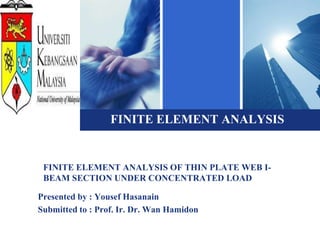
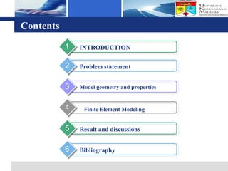
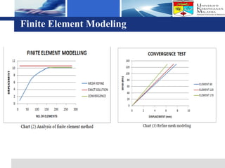
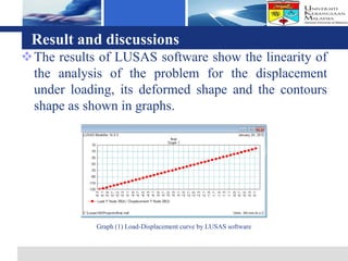
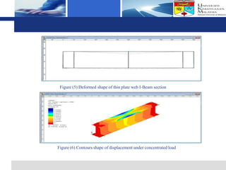
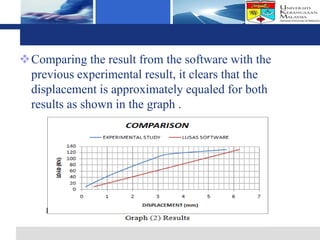
The document presents a finite element analysis of thin plate web I-beam sections under concentrated loads, focusing on modeling, results, and discussions related to displacement and stress. The study utilized LUSAS software to compare the results of numerical analysis with previous experimental findings, revealing that the finite element method accurately reflects the load-displacement behavior. The conclusions indicate that the model's outcomes align closely with experimental results, demonstrating the effectiveness of the software for precise analyses in engineering applications.