Downloaded 1,092 times


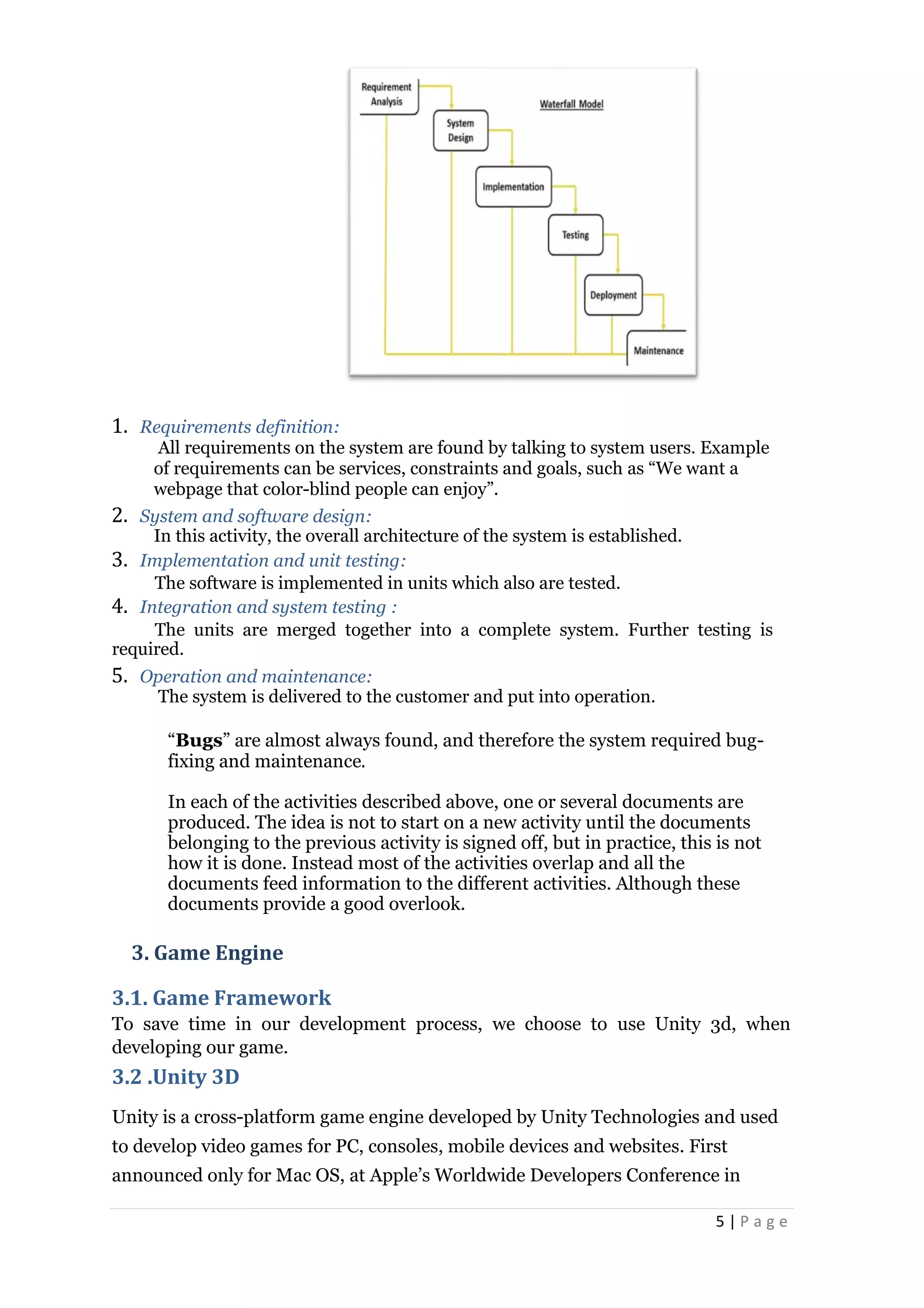


![36 | P a g e
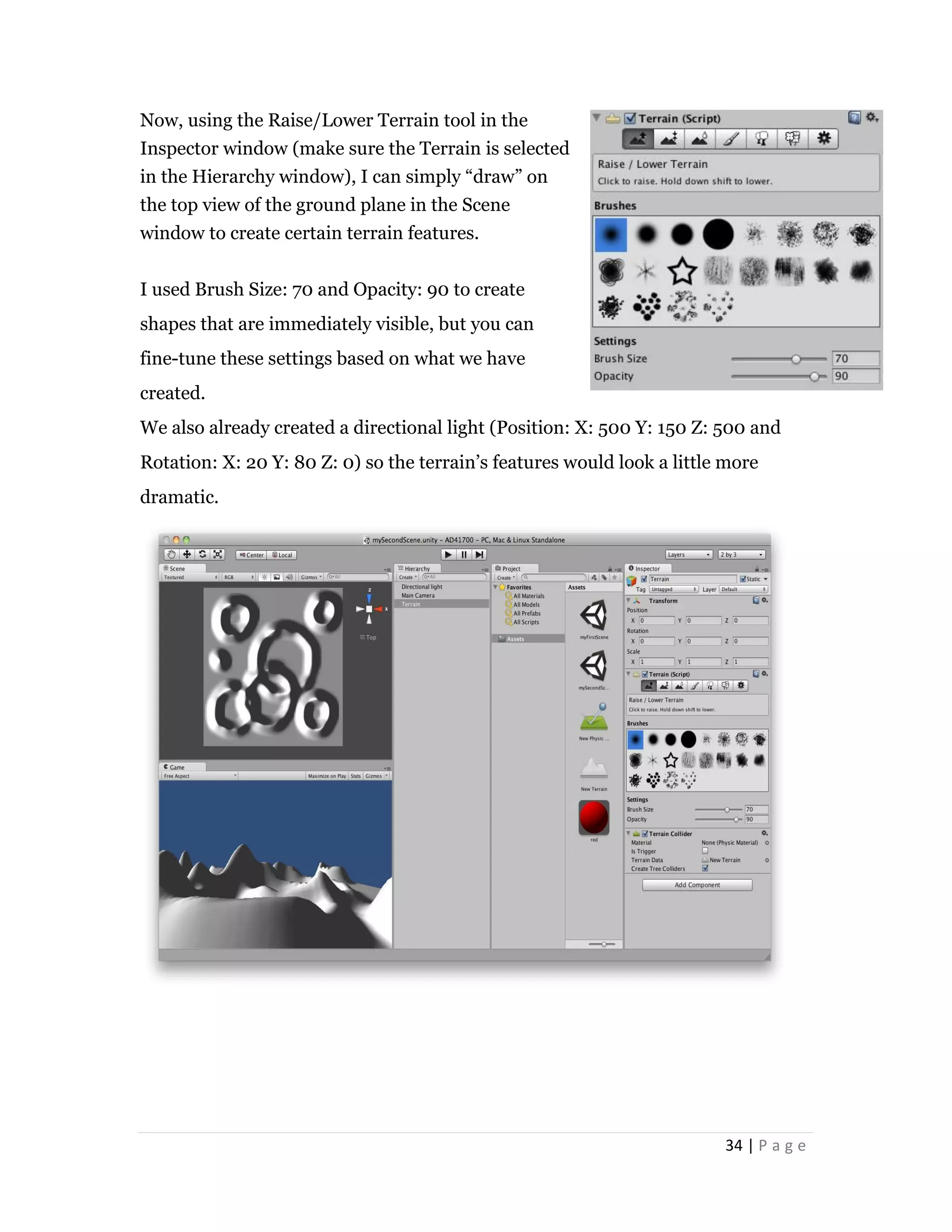
In the property Inspector you will
see the EasyRoads3D toolbar:
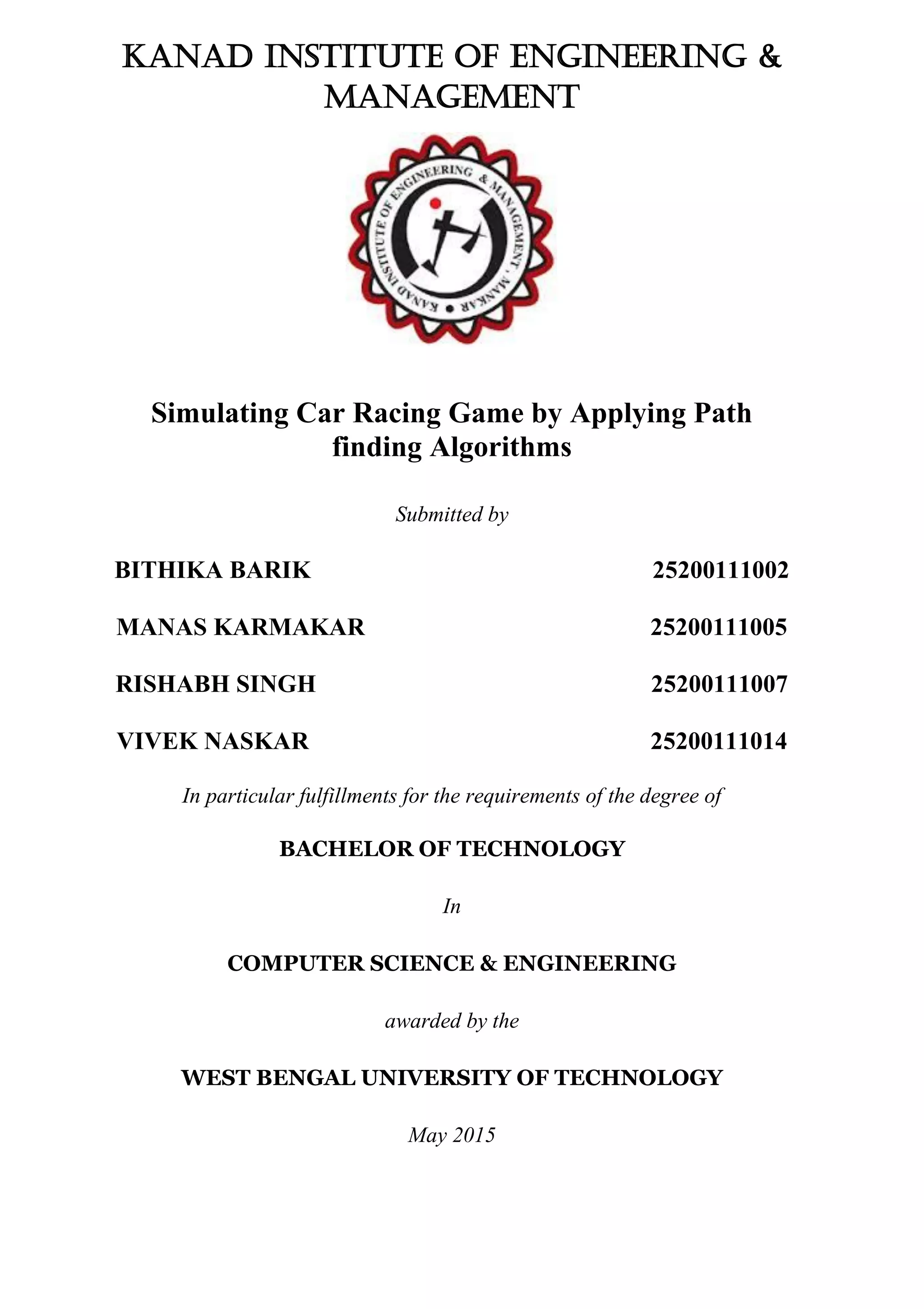
9.1. Add Road Markers
Add road markers by activating the Add Markers toolbar tab. Move the mouse to
the position where you want the road to start and click the left mouse button
while holding the [shift] key.
Continue adding markers according the shape of the desired road. We will see
that the road system will create surfaces representing the road and the affected
surrounding which are configurable in General Settings.
9.2. Insert Road Markers
Insert road markers works similar as adding road markers but instead of adding
the marker at the end of the road, it will insert the marker between the 2 closest
markers to the mouse position. Make sure you are in Insert Markers mode by
activating the Insert Markers toolbar tab!
NOTE: In order to add or insert markers make sure is active!
Additional Marker Functions
When two markers are selected you will see the below buttons in the Inspector:](https://image.slidesharecdn.com/ee4a397e-b027-448a-bf85-91df7e1c3093-150609150151-lva1-app6892/75/Car-Game-Final-Year-Project-41-2048.jpg)

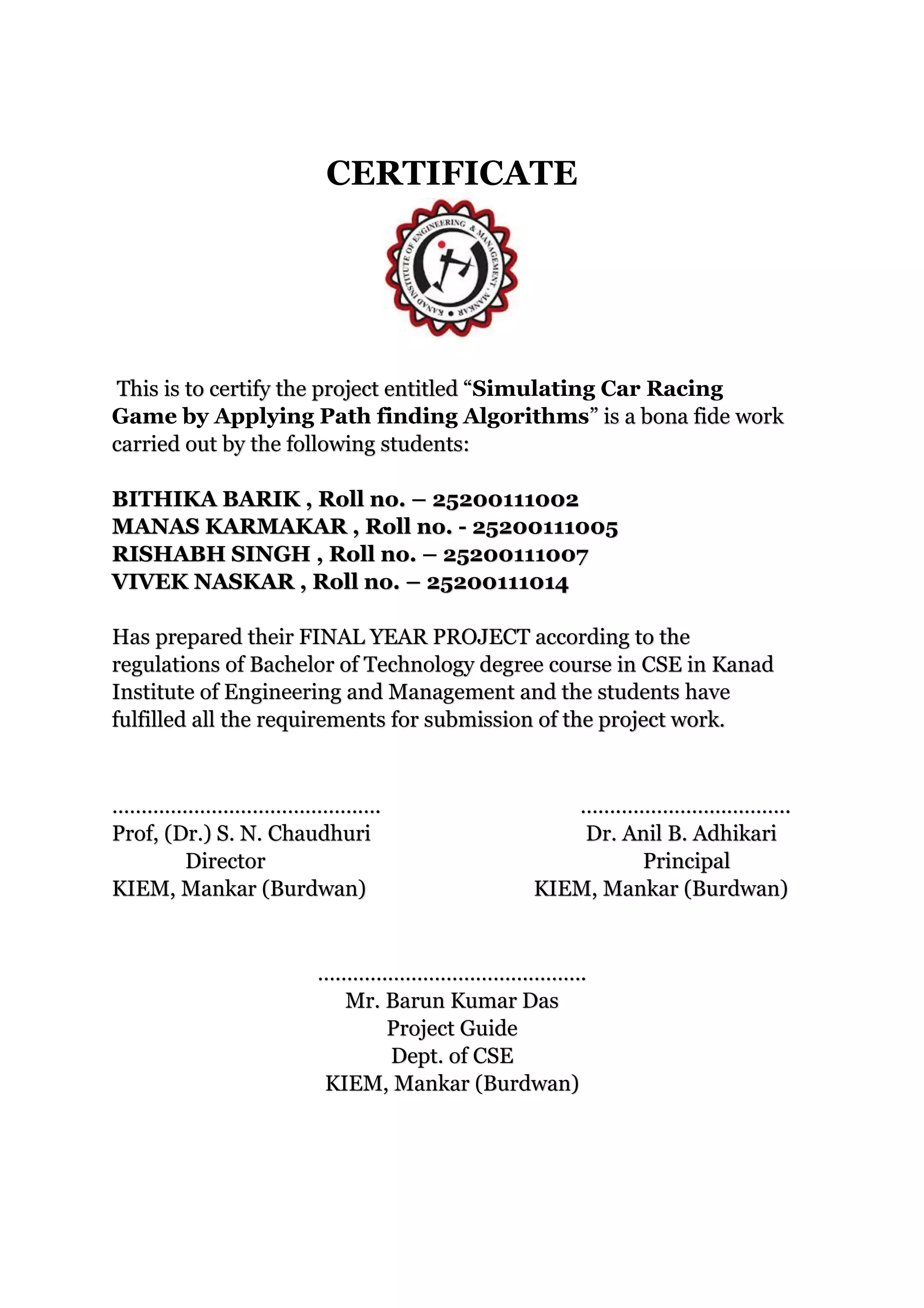
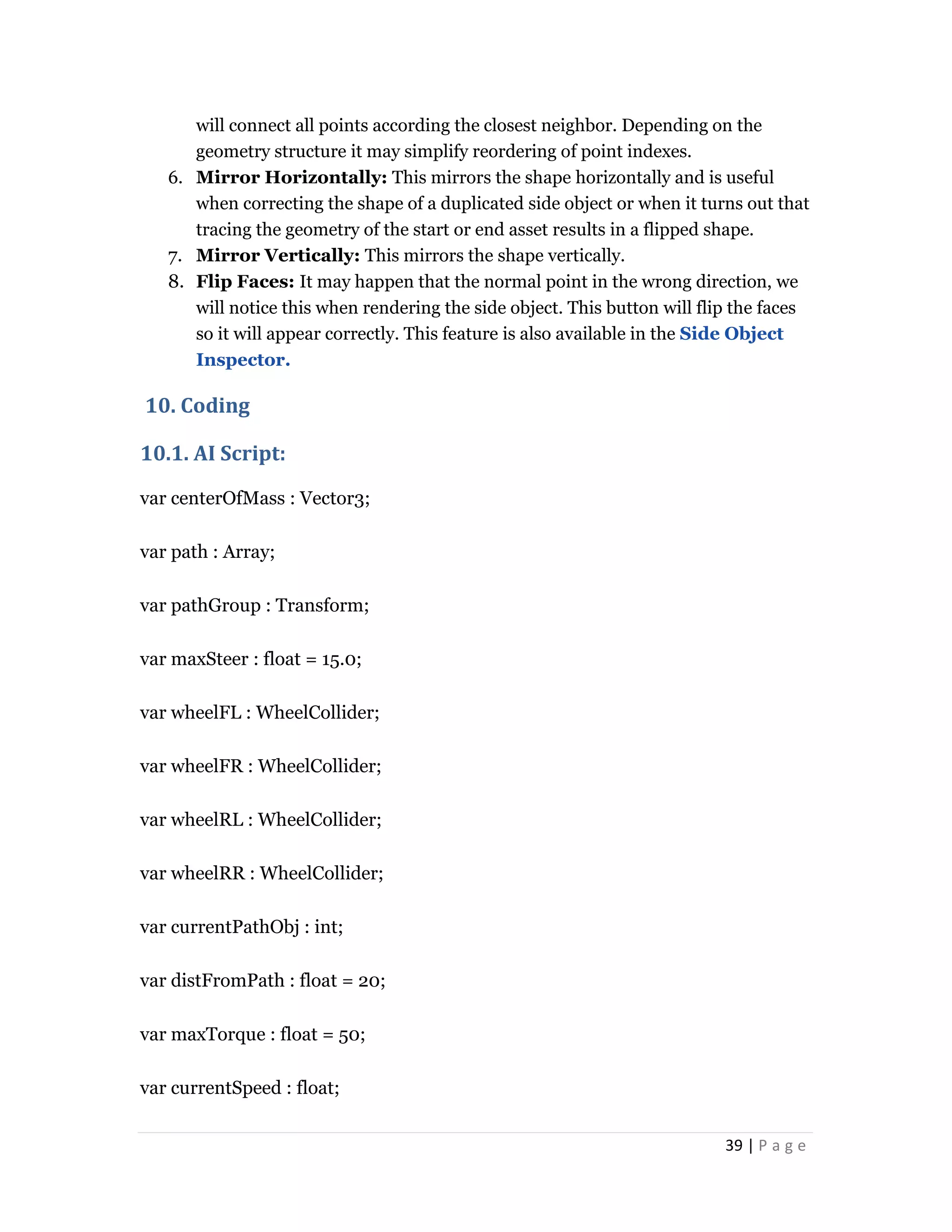
![38 | P a g e
The editor window gives a 2D representation of the shape of the procedural
geometry. We can define any shape we want:
1. Add new vertical positions by double clicking on the stage there where we
want to position the new point. Points will be connected to give a clear idea of
the shape.
2. Move points by selecting them (the point turns red) and dragging it while
keeping the mouse down.
3. Delete points with the "Backspace" or "Delete" key.
Controls / Hot Keys:
[Shift] click: Select and drag or delete multiple points
[Control] double click: Insert a point between the two closest points
Z key: Zooms the grid so all the points are clearly visible
R key: Resets the zoom and positioning to the original values
Mouse down: and drag, will move the grid
[alt] drag stage on Y-axis, Mouse scroll, [Command] & drag, right mouse
button & drag: Zooms in / out on the grid.
Side Object Geometry Controls:
1. Selected Index: When we select a point the associated index value will be
displayed in the ComboBox. The purpose of this is become explained in the
NOTE here below.
2. Close Geometry: When checked, the first and last point will connect.
3. Trace Object: if we added a Start or / and End object to the associated slots
in the Object Manager this object will appear here. It can be used to
analyze the geometry and automatically define the shape of the procedural
geometry accordingly. Make sure that those vertices used to connect the start
and end assets with the procedural with each other are at position 0 on,
depending on our modeling application, the y-axis or z-axis.
4. Trace On: Depending on the rotation of the asset we may have to switch
between x-axis, y-axis and z-axis until we clearly see the shape that the
procedural geometry should have. By default objects are traced on the z-axis
when opening the editor window and no points are stored yet for this side
object.
5. Auto Connect: Below the situation is described where we can clearly see
that the dots are positioned correctly but they do not connect in the right
order. Auto Connect will be enabled when we select the first point, from this it](https://image.slidesharecdn.com/ee4a397e-b027-448a-bf85-91df7e1c3093-150609150151-lva1-app6892/75/Car-Game-Final-Year-Project-43-2048.jpg)
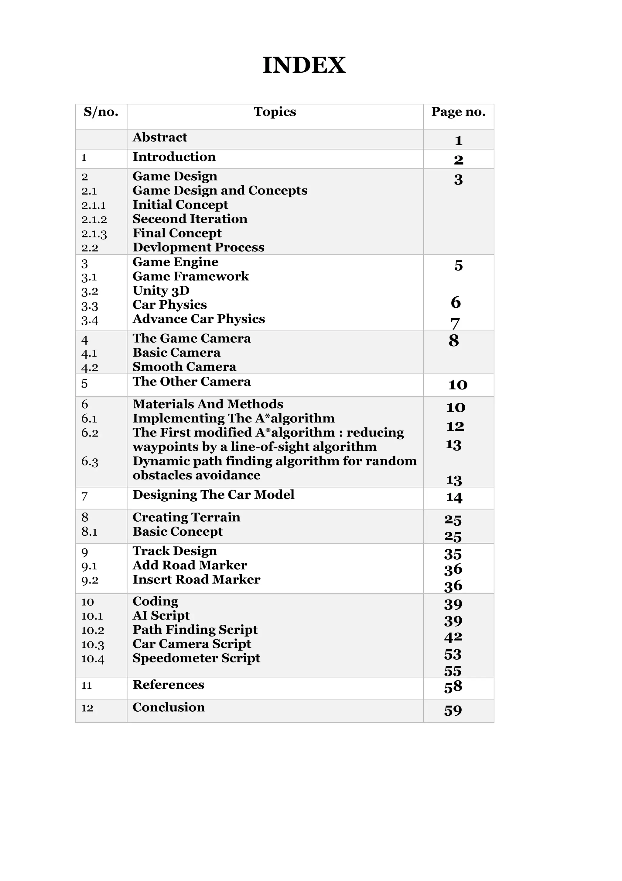
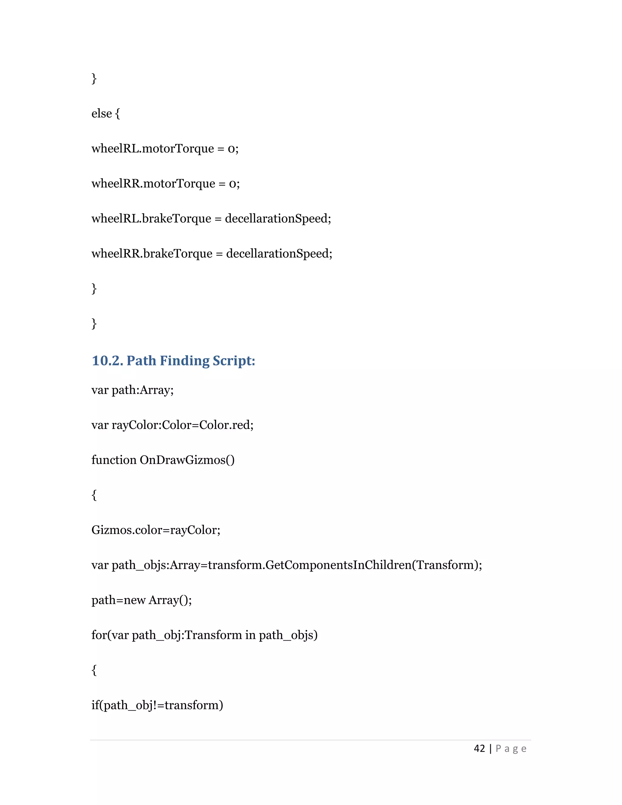
![40 | P a g e
var topSpeed : float = 150;
var decellarationSpeed : float = 10;
function Start () {
rigidbody.centerOfMass = centerOfMass;
GetPath();
}
function GetPath (){
var path_objs : Array = pathGroup.GetComponentsInChildren(Transform);
path = new Array();
for (var path_obj : Transform in path_objs){
if (path_obj != pathGroup)
path [path.length] = path_obj;
}
}
function Update () {
GetSteer();
Move();
}
function GetSteer(){](https://image.slidesharecdn.com/ee4a397e-b027-448a-bf85-91df7e1c3093-150609150151-lva1-app6892/75/Car-Game-Final-Year-Project-45-2048.jpg)
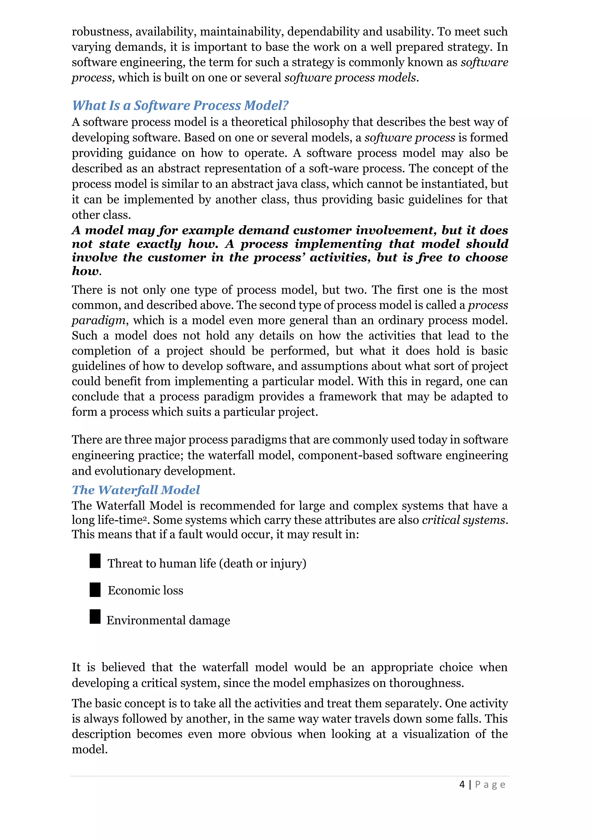
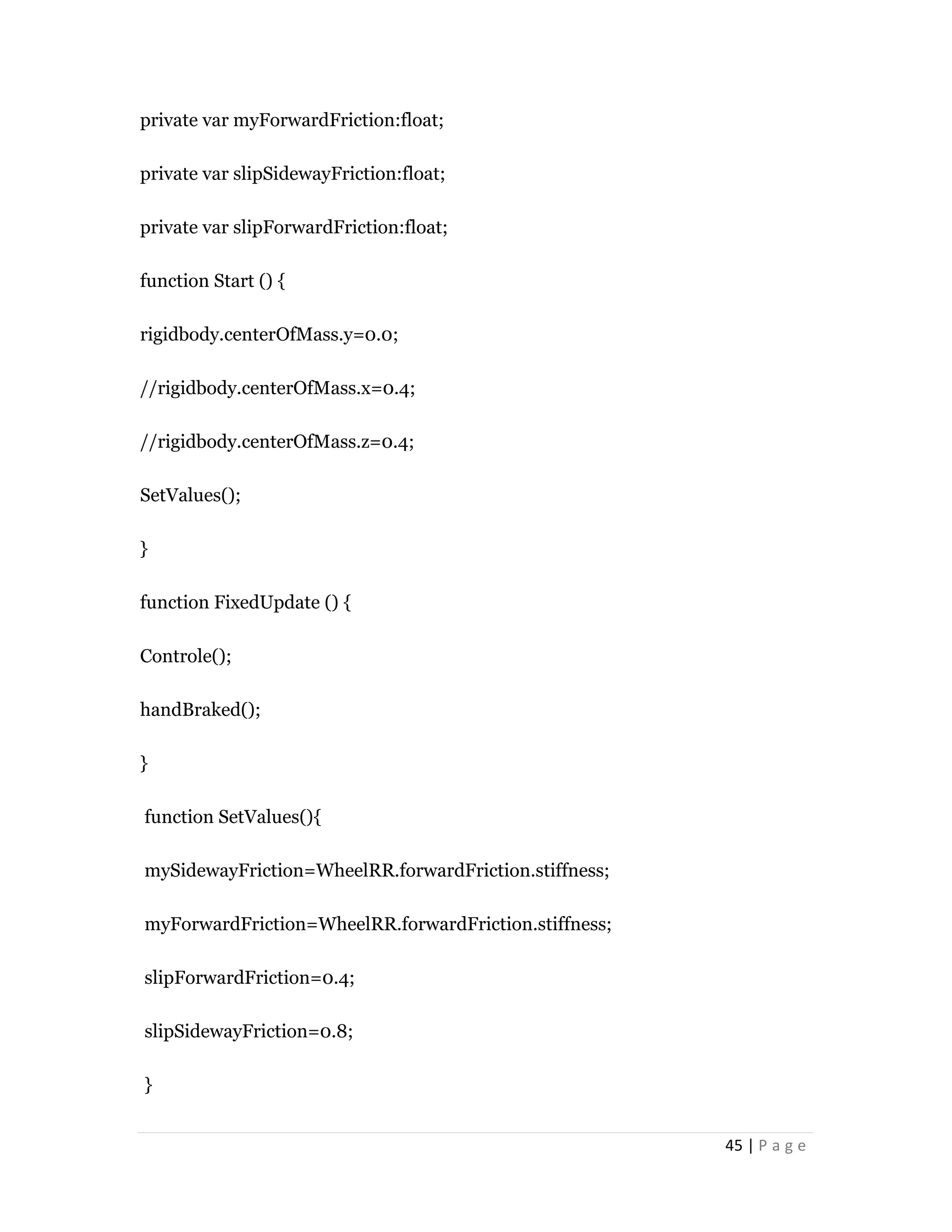
![41 | P a g e
var steerVector : Vector3 =
transform.InverseTransformPoint(Vector3(path[currentPathObj].position.x,tran
sform.position.y,path[currentPathObj].position.z));
var newSteer : float = maxSteer * (steerVector.x / steerVector.magnitude);
wheelFL.steerAngle = newSteer;
wheelFR.steerAngle = newSteer;
if (steerVector.magnitude <= distFromPath){
currentPathObj++;
if (currentPathObj >= path.length)
currentPathObj = 0;
}
}
function Move (){
currentSpeed = 2*(22/7)*wheelRL.radius*wheelRL.rpm * 60 / 1000;
currentSpeed = Mathf.Round (currentSpeed);
if (currentSpeed <= topSpeed){
wheelRL.motorTorque = maxTorque;
wheelRR.motorTorque = maxTorque;
wheelRL.brakeTorque = 0;
wheelRR.brakeTorque = 0;](https://image.slidesharecdn.com/ee4a397e-b027-448a-bf85-91df7e1c3093-150609150151-lva1-app6892/75/Car-Game-Final-Year-Project-46-2048.jpg)
![43 | P a g e
path[path.length]=path_obj;
}
for(var i:int=0;i<path.length;i++)
{
var pos:Vector3=path[i].position;
if(i>0)
{
var prv=path[i-1].position;
Gizmos.DrawLine(prv,pos);
Gizmos.DrawWireSphere(pos,0.3);
}
}
}
Car control script:
#pragma strict
var WheelFL : WheelCollider;
var WheelFR : WheelCollider;
var WheelRL : WheelCollider;
var WheelRR : WheelCollider;](https://image.slidesharecdn.com/ee4a397e-b027-448a-bf85-91df7e1c3093-150609150151-lva1-app6892/75/Car-Game-Final-Year-Project-48-2048.jpg)


This document describes the development of a 3D racing car game using an agile evolutionary development process. The game was created using Unity 3D for the engine. Over multiple iterations, the game concept evolved from a deathmatch-style racing game to a kart racing game where players collect coins and powerups. Pathfinding algorithms were implemented to control the AI. Advanced car physics were added using forces and torques rather than direct position and rotation control. Terrain, tracks, and 3D car models were designed and created in modeling programs then imported. Scripts were written for the AI, pathfinding, cameras, and HUD elements.


![+Game dev vs traditional software engineering [recovered]](https://cdn.slidesharecdn.com/ss_thumbnails/gamedevvstraditionalsoftwareengineeringrecovered-161026235746-thumbnail.jpg?width=640&height=640&fit=bounds)


