Downloaded 24 times

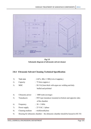
![SURFACE TREATMENT OF AEROSPACE COMPONENTS 2014
DSCE, CHEMICAL ENGINEERING DEPARTMENT Page 25
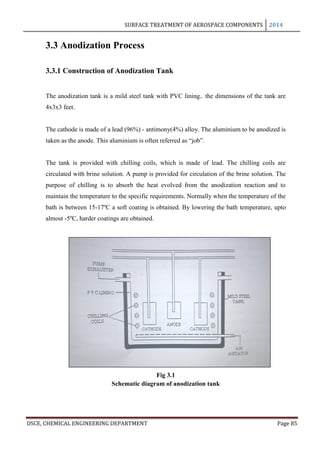
and decorations, while corrosive sea water may enter the boilers of a power station if the
condenser tubes perforate.
7. Loss of technically important surface properties of a metallic component. These could
include frictional and bearing properties, ease of fluid flow over a pipe surface, electrical
conductivity of contacts, surface reflectivity or heat transfer across a surface.
8. Mechanical damage to valves, pumps, etc, or blockage of pipes by solid corrosion products.
9. Added complexity and expense of equipment which needs to be designed to withstand a
certain amount of corrosion, and to allow corroded components to be conveniently replaced.
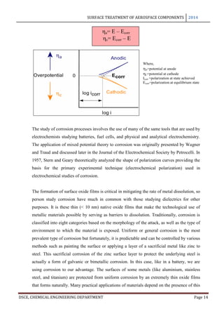
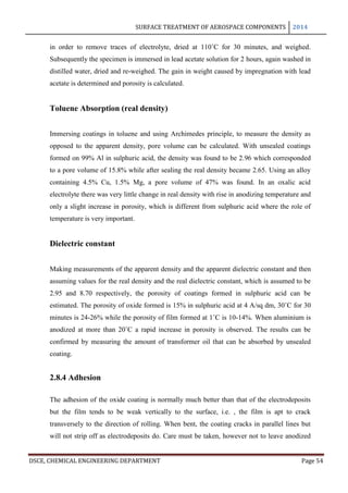
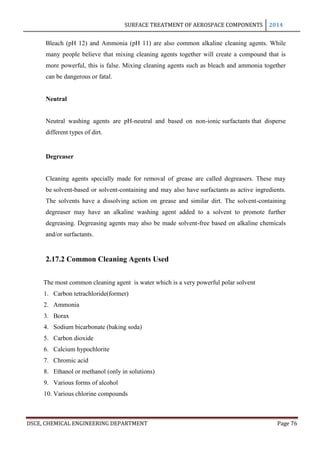
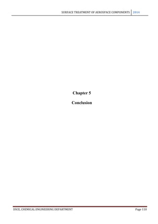
In light of the thermodynamic basis for corrosion it is not surprising that costs associated
with corrosion are high.
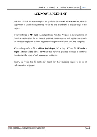
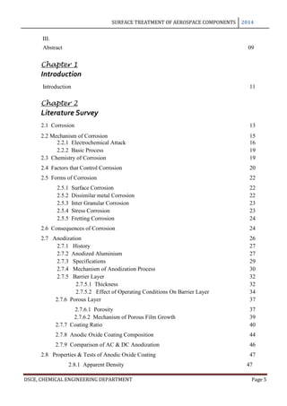
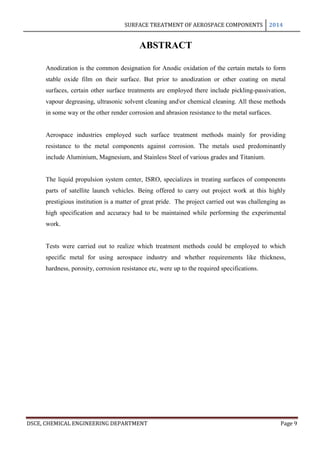
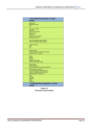
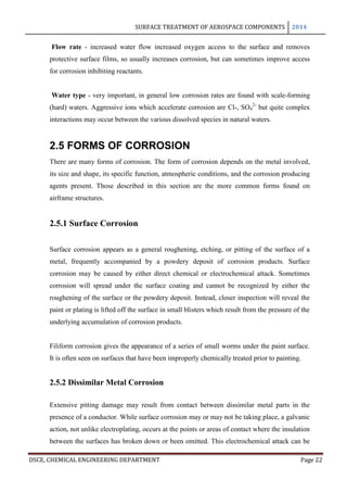
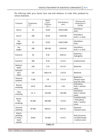
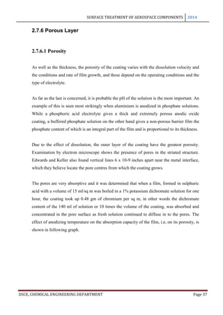
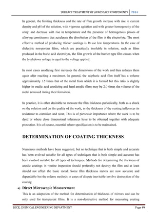
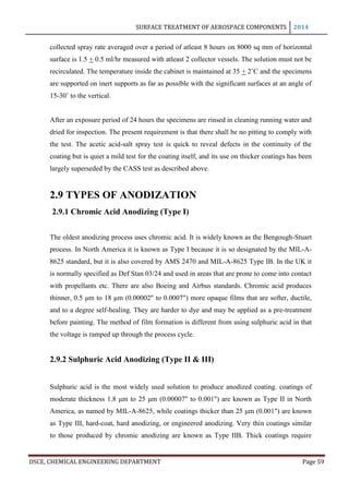
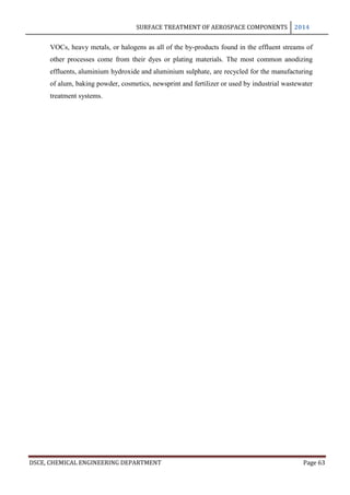
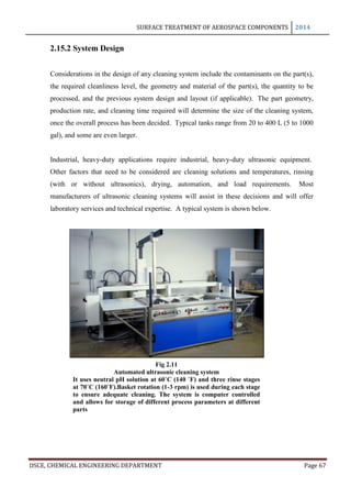
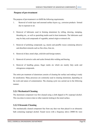
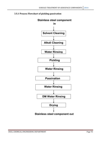
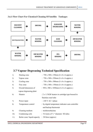
Several studies over the past 30 years have shown that the annual direct cost of corrosion to
an industrial economy is approximately 3.1% of the country’s Gross National Product
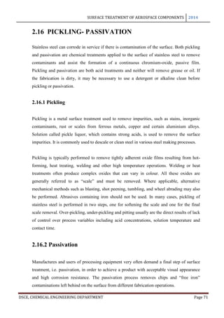
(GNP). In the United States, this amounts to over $276 billion per year. It is revealed that
the highest segments of the cost of corrosion are associated with utilities, transportation, and
infrastructure. The Department of Defence alone has corrosion costs of $20 billion [6]
.
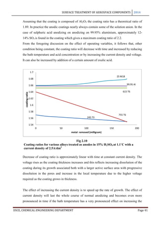
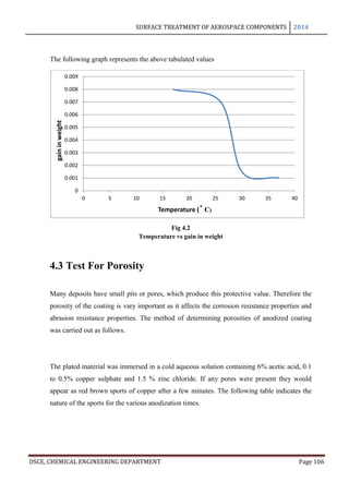
Fig 2.2
Cost of corrosion in the US](https://image.slidesharecdn.com/617f112a-6fc3-4626-9ccd-362dc8008591-150414151719-conversion-gate01/85/final-report-edit-25-320.jpg)
![SURFACE TREATMENT OF AEROSPACE COMPONENTS 2014
DSCE, CHEMICAL ENGINEERING DEPARTMENT Page 31
the resistance of the film prevents the current from reaching the anode. They can be formed
in a number of electrolytes of which borate or tartarate solutions are the most common
examples. Such films, formed at high voltage, find application in the production of the
electrolytic condensers and for protection for very thin aluminium coating, example, those
applied by vacuum deposition.
3. The reaction products may be sparingly soluble in the electrolyte and form a strongly
adherent film that is non-conducting when dry, over the anode.
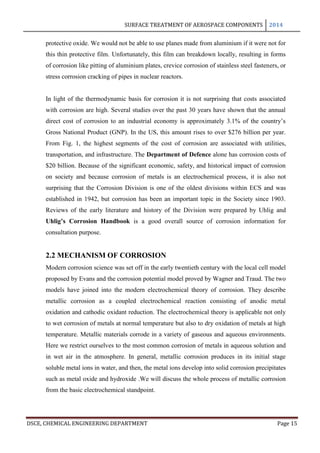
In this case film growth takes place as above but is accompanied by dissolution of film at the
surface. Pores are thus formed in the coatings that are wide enough to allow continuous
access of the current to the metal. Film growth continues while the electrical resistance
increases. When the rate of film growth has decreased until it is equal to the rate of
dissolution of the film in the electrolyte, the film thickness remains constant.
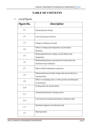
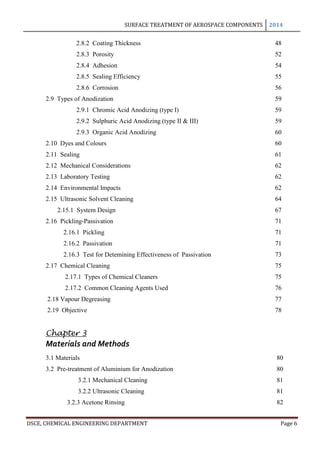
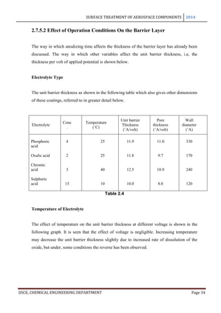
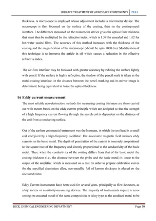
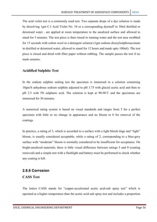
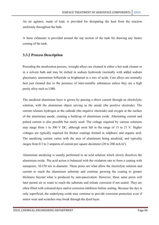
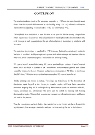
The maximum film thickness varies with the electrolyte and the operating conditions,
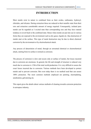
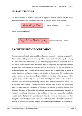
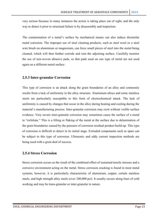
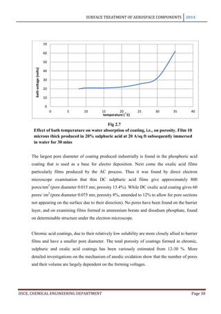
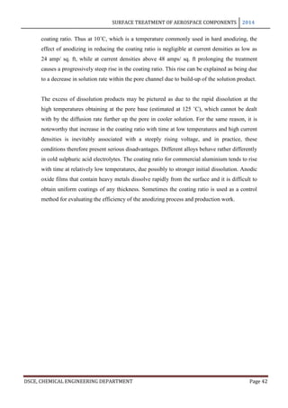
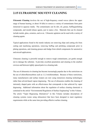
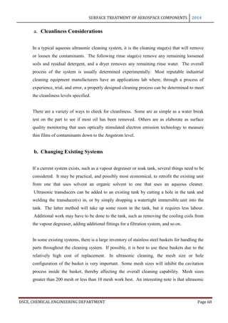
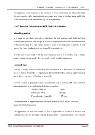
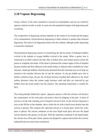
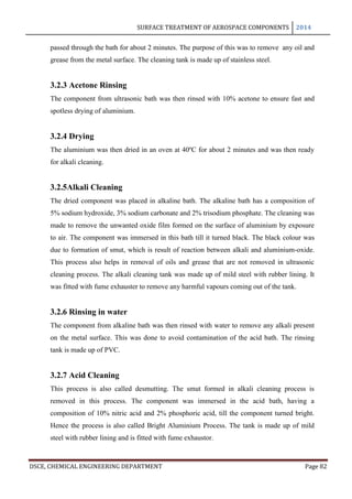
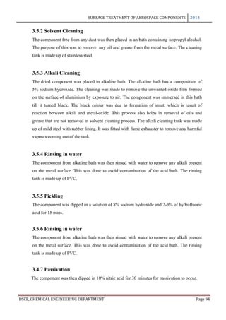
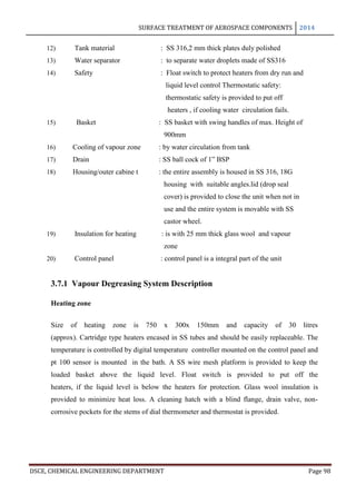
especially the temperature which affects the dissolution velocity. The way in which the film
thickness and thickness of the basic sheet vary with time is shown in the following figure.
The curve A refers to the total increase in thickness of a sheet anodized on both sides to the
coating thickness indicated by curve B, while the curve A’ refers to the dimensional change
of a single surface. The coating reaches its maximum thickness in just almost 2 hours and it
may be seen that upto this point, for every 3 microns of coating formed the metal surface
retreats approximately to 2 microns and the exterior surface advances 1 micron.
These are the conditions of industrial anodization process that are based chiefly on chromic,
sulphuric or oxalic acid.
4. The reaction products may be moderately soluble. Under these conditions electro-polishing
may be possible if a suitable electrolyte is used. Apart from the reactions considered there
are a variety of less important possibilities, for example, where the reaction products may
form loosely adherent, spongy or powdery deposits, as when the anodizing solutions become
contaminated or when anodizing under special operations. A continuous adherent insoluble
film, a few molecules thick, may render the metal passive [7]
.](https://image.slidesharecdn.com/617f112a-6fc3-4626-9ccd-362dc8008591-150414151719-conversion-gate01/85/final-report-edit-31-320.jpg)
![SURFACE TREATMENT OF AEROSPACE COMPONENTS 2014
DSCE, CHEMICAL ENGINEERING DEPARTMENT Page 32
2.7.5 Barrier Layer
2.7.5.1 Thickness
It was shown as early as 1932 by Steoh and Miyata that the anodic oxide film consists of
two layers, the porous thick outer layer growing on an inner layer which is thin, dense and
dielectrically compact, and usually called the active layer, barrier layer or dielectric layer.
This layer is very thin, i.e, usually between 0.1 and 2.0% of the total film, and its thickness
depends on the composition of the electrolyte and the operating conditions. It has been
established that the barrier layer formed in anodizing is of the nature of the natural oxide
film formed in the atmosphere and that the barrier layer and porous films can also be
distinguished coatings and on electro polished surfaces.
In anodizing, the barrier layer is formed first and its thickness varies directly with the
forming voltage. The barrier layer is non porous and conducts current only due to its
thinness and faults in its skeleton. The outer layer, on the other hand, is micro porous and
built upon a columnar structure. As long as no dissolution occurs in the electrolyte, the
barrier layer is formed in a thickness of 14 A per volt. This is the theoretical maximum
approached only in solutions in which little or no solvent occurs: thus, Holland and
Sutherland obtained film thicknesses of 13 A per volt in 3% ammonium tartarate solution
used in the protection of vacuum coated aluminium mirrors. Capacity measurements of
barrier layers by Ginsberg and Kadan have given values of 14 A per volt for films formed in
barrier layer electrolytes and 11.5 A per volt for barrier layers for porous anodic coatings [8]
.](https://image.slidesharecdn.com/617f112a-6fc3-4626-9ccd-362dc8008591-150414151719-conversion-gate01/85/final-report-edit-32-320.jpg)


![SURFACE TREATMENT OF AEROSPACE COMPONENTS 2014
DSCE, CHEMICAL ENGINEERING DEPARTMENT Page 113
[1] Sheas by & Pinner 2001, pp. 427–596.
[2] Sheas by & Pinner 2001, pp. 597–742.
[3] Davis 1993, p. 376.
[4] Sheasby & Pinner 2001, p. 5.
[5] Sheasby & Pinner 2001, p. 9.
[6] Edwards, Joseph (1997). Coating and Surface Treatment Systems for Metals. Finishing
Publications Ltd. (pp. 34–38).
[7] Kutz, Myer. "Protective coatings for aluminum alloys". Handbook of Environmental
Degradation of Materials. Norwich, NY: William Andrew. p. 353.
[8] Sheasby & Pinner 2001, pp. 327–425.
[9] US Military Specification MIL-A-8625, ASSIST database
[10] http://www.ecmjournal.org/journal/supplements/vol005supp01/pdf/vol005supp01a18.df
[11] Edwards, Joseph (1997). Coating and Surface Treatment Systems for Metals. Finishing
Publications Ltd. pp. 39–40. .
[12] ANODIZING OF ZINC FOR IMPROVED SURFACE PROPERTIES M. A.
[13] Biason Gomes, M. A.; S. Onofre, S. Juanto, L. O. de S. Bulhões (1991). "Anodization
of niobium in sulphuric acid media". Journal of Applied Electrochemistry 21 (11
[14] Chiou, Y. L. (1971). "A note on the thicknesses of anodized niobium oxide films". Thin
Solid Films 8 (4): R37–R39.
[15] "Anodizing and the environment". Archived from the original on 8 September Retrieved
2008-09
[16] Davis, Joseph R. (1993). Aluminum and Aluminum Alloys (4th ed.). ASM International.
[17] Sheasby, P. G.; Pinner, R. (2001). The Surface Treatment and Finishing of Aluminum
and its Alloys 2 (sixth ed.). Materials Park, Ohio & Stevenage, UK: ASM International &
Finishing Publications.
[18] Wisniewski, Karen (2007). "All-Purpose Cleaners and their Formulation". In Tsoler,
Uri. Handbook of detergents, Part 2. Surfactant science series.
[19] Corrosion in aerospace industry. Pdf
[20] Corrosion protection- basic corrosion theory and methods by Dr. Thomas J. Langill
[21] What is Corrosion? Pdf by Barbara A. Shaw and Robert G. Kelly
[22] Durability Of Concrete Structures ch – 2 Mechanism Of Corrosion
[23] Anodizing Aluminum By Ron Newman](https://image.slidesharecdn.com/617f112a-6fc3-4626-9ccd-362dc8008591-150414151719-conversion-gate01/85/final-report-edit-113-320.jpg)
![SURFACE TREATMENT OF AEROSPACE COMPONENTS 2014
DSCE, CHEMICAL ENGINEERING DEPARTMENT Page 114
[24] Stereometry specification of anodization surface of casting aluminium alloys J.
Konieczny , K. Labisz a, J. Wieczorek , L. A. Dobrzański
[25] TECHNICAL BULLETIN Anodize & Hardcoat Anodize ALUMINUM PROTECTION
FROM WITHIN (Type II Sulfuric Acid & Type III Sulfuric Acid) MIL-A-8625
[26] 204-R1 Anodized Finish
[27] HM wire international Inc.pdf
[28] INFORMATION SHEET anodizing. Pdf
[29] Anodising.pdf
[30] Aluminum Anodizingby AACOA, Inc.
[31] Weatherfoerd process chemical cleaning and flushing
[32] Chemical Surface Treatment of Stainless Steel Types of Process,
[33] A designers handbook cleaning and descaling of stainless steel
[34] Tech tips: Passivation of Stainless Steel. Pdf
[35] FUNDAMENTALS OF ULTRASONIC CLEANING By James R Heson
[36] Ultrasonic Vapor Degreaser](https://image.slidesharecdn.com/617f112a-6fc3-4626-9ccd-362dc8008591-150414151719-conversion-gate01/85/final-report-edit-114-320.jpg)

This document provides an overview of surface treatment methods for aerospace components, including anodization, ultrasonic solvent cleaning, pickling-passivation, chemical cleaning, and vapour degreasing. It acknowledges those who helped with the project work. Tables of contents and figures/tables are included. The abstract indicates that tests were conducted to determine which surface treatment methods are suitable for different metals used in aerospace and whether thickness, hardness, porosity, and corrosion resistance met specifications.


