1. Surface Science and Engineering
(Subject Code , No. of Credits: 4)
Syllabus:
Introduction, structure and types of interfaces, surface energy and related equations, classification, definition, scope and
general principles of surface engineering, surface engineering by material removal, surface engineering by material addition, surface
modification of steel and ferrous components, surface modification of ferrous and non-ferrous components, surface modification using
liquid/molten bath, surface engineering by energy beams and spray techniques, characterization of surface microstructure and
properties, evaporation, sputter deposition of thin films and coatings, hybrid/modified PVD coating processes, CVD and PECVD,
plasma and ion beam assisted surface modification, surface modification by ion implantation and ion beam mixing, measurement of
coating thickness, porosity, adhesion of surface coatings, residual stress and stability, surface microscopy and topography by scanning
probe microscopy, spectroscopic analysis of modified surfaces, functional and nano structured coatings and their applications, surface
passivation of semiconductors and effect on electrical properties, surface engineering of polymers and composites, thin film
technology for multi-layers and super lattices for electronic, optical and magnetic devices.
References:
1. K.G. Budinski, Surface Engineering for Wear Resistance, Prentice Hall, Englewood Cliffs, 1988.
2. M. Ohring, The Materials Science of Thin Films, Academic Press Inc, 2005.
2. Surface Science and Engineering
(Subject Code: , No. of Credits: 4)
Detailed Syllabus:
Unit-I: Introduction: Fundamentals of surface engineering, Importance of Surface engineering, Evolution and Significance of
Surface engineering, Classification of Surface engineering process, Surface Energy, The significance of surface, treatment of metals,
Surface preparation techniques.
Unit-II: Conventional surface engineering 1: Surface, Surface engineering metal removal techniques, Surface engineering by Metal
addition, Electro deposition/Plating, Surface modification of Ferrous and Non-ferrous alloys, Carburizing, Nitriding, Cyaniding etc.,
Unit-III: Conventional surface engineering 2: High temperature corrosion followed by protective coating, passivity, Pilling-
Bedworth ratio, Oxidation rates, Conversion coating, Phospating, Chromating, Hydrogen Attack, Anodizing,
Unit-IV: Advanced Surface engineering practices 1: Surface treatment Methods, Flame hardening, Induction hardening, Laser
beam Hardening, Plasma spraying, Sputter deposition, Physical vapor deposition (PVD), Chemical vapor deposition (CVD), Ion-
implation.
Unit-V: Advance Surface engineering practices 2: Thermal spraying, Classification of Thermal spraying, Flame spraying
techniques, Electric Arc spraying, Cold spraying.
Unit-VI: Characterization of Coatings: Measurements of Coating thickness, Evolution of Mechanical properties, Evolution of
coating Adhesion, Hardness Test, Evolution of Crystallographic structure of Surface by X-RD, Evolution of Surface morphology &
Microstructural properties by (SEM&TEM).
Resources:
(1) K.G. Budinski, Surface Engineering for Wear Resistance, Prentice Hall, Englewood Cliffs, 1988.
2) M. Ohring, The Materials Science of Thin Films, Academic Press Inc, 2005.
3) Surface engineering of Metals principles, Equipments, Technologies by T.Burakowski, T. Wierzchon( Poland ),Washington
CRC press 2009.
3. 4) Surface treatment of metals for Adhesive bonding second eddition by Sina Ebnesajjad, USA, 2006&2014.
5) Advance thermally Assisted Surface Engineering Processes by Ramnarayan Chattopadhyay India.,Kluer Acedamic
Publishers.,2004.
Units of
syllabus
Study Material
by Dr. P. Justin
Video Lectures
Prof. A.K.
Chattopadhyay, IIT-
kharagpur
Assignments Examination details
Unit-I
&
Unit-II
Lecture 1: Introduction to
Surface Engineering (9 Pages)
Video lecture 1: Surface
Coating (57:39min)
Assignment-1
Assignment-2
Assignment-3
Mid 1
(20 Marks
Descriptive)
Syllabus
covered within
first 25 days of
instruction
period
EST
(20 Marks Objective
& 40 Marks
Descriptive)
Syllabus covered in
total 80 days of
instruction period in
a semester
Module 2: Surface and Surface
Energy (11 Pages)
Lecture 3: Surface Engineering
by Metal removal (24 Pages)
Lecture 4: Surface Engineering
by Metal addition(Electro
plating)
(19 Pages)
Video lecture 2 : Electro
plating ( 58 min )
Lecture 5: Surface Alloying
(9 Pages)
Lecture 6: Nitriding (11 Pages)
Lecture 7: Carburizing (9
Pages)
Lecture 8 : Other hardening
techniques(Boriding,
Aluminizing, Cyaniding) (8
Pages)
4. Unit-III
&
Unit-IV
Lecture 9 : Surface engineering
by Passivity (30 Pages)
Assignment-4
Assignment-5
Assignment-6
Assignment-7
Assignment-8
Assignment-9
Mid 2
(20 Marks
Descriptive)
Syllabus
covered within
second 25 days
of instruction
period
Lecture 10 : Hydrogen Attack
(17 Pages)
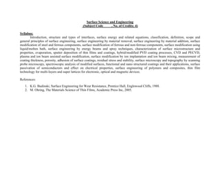
Lecture 11 : High temperature
Corrosion(27 Pages)
Lecture 12 : Conversion coating
by Anodizing (31 Pages)
Video lecture 16 :
Anodizing
( 59 min )
Lecture13 :Conversion coating
Followed by Phosphate,
Chromate& Oxide (15 Pages)
Lecture 14 : Surface Hardening
Techniques (74 Pages)
Lecture 15 : Flame Hardening
(49 Pages)
Lecture 16 : Induction
Hardening (33 Pages)
Lecture 17 : Surface
engineering by Plasma spray
Technique
(11 Pages)
Video Lecture 22 : Plasma
Spray technique ( 59 min )
Lecture 18 : Sputter Deposition
of Thin films (12 Pages)
Video Lectures
20,21,22,23,24,25,26 :
Sputter Deposition ( 1:00:00
hr each)
Lecture 19 : Physical Vapor
Deposition Technique (26
Video Lecture 6 : PVD
( 59:45 min )
5. Unit-V
&
Unit-VI
Pages)
Lecture 20 : Ion-Implantation
(47 Pages)
Lecture 21 : Chemical Vapor
Deposition _ CVD (26 Pages)
Video Lectures :
7,8,9,10,11,12,13,14,15
(1:00:00hr each)
Lecture 22 : Thermal Spray
coating by Flame Spray
technique (15 Pages)
Video Lecture 17 : Thermal
Spray Process ( 57:30 min)
Lecture 23 : Cold Spray
Technique (22 Pages)
Lecture 24 : Introduction to
Surface Characterization
Techniques (6 Pages)
Video Lecture 27&28 :
Characterization of Surface
coatings ( 59 min each)
Lecture 25 : Surface
Characterization Techniques
(17 Pages)
Video Lecture 29&30 :
Characterization of Surface
coatings ( 58 min each)
7. 2
Definition
Modification of near-surface structure, chemistry or property of a
substrate in order to achieve superior performance and/or durability. It is
an enabling technology and can impact a wide range of industrial sectors.
Surface Engineering is the
“The treatment of the surface
and near surface regions of a
material to allow the surface to
perform functions that are
distinct from those functions
demanded from the bulk of the
material.
Surface science is a branch of physical
organic chemistry that studies the
behavior and characteristics of molecules
at or near a surface or interface
8. It is an enabling technology for which the participating research
groups and industry have outstanding positions.
Products for tomorrow require thin film materials based on the
processes that we are currently exploring.
These may be flat panel displays, DVD’s, bio implants, precision
bearings, high-frequency filters, magnetic memories and sensors, durable light
metal alloy components for engines, x-ray mirrors, chemical- and biosensors,
and optical coatings. In particular, our research caters directly to the tooling,
automotive, electro technical, biomedical, energy, and electronic industry
sectors.
3
Importance
It can be done on a given surface by Metallurgical, mechanical, physical, and
chemical means, or by producing a thick layer on a thin coating
Both metallic and non-metallic surfaces can be engineered to provide
improved property or performance.
9. 4
Wear, friction, corrosion, fatigue, reflectivity, emissivity,
color, thermal/electrical conductivity, bio-compatibility, etc.
Benefits
Extend product life (durability)
Improve resistance to wear, oxidation and corrosion
(performance)
Satisfy the consumer's need for better and lower cost
components
Reduce maintenance (reliability and cost)
Reduce emissions and environmental waste
Improve the appearance; visually attractivity
Improve electrical conductivity
Improve solderability
Metallize plastic component surfaces
Provide shielding for electromagnetic and radio frequency
radiation.
Specific properties rely on Surface
10. 5
Evolution and Significance of Surface engineering
It is an enabling technology
It can combine various surface
treatments with thin film and
coating deposition.
It can substantially improve wear
and corrosion resistance of
structural components.
It increases component lifetime
and resistance to aggressive
environments.
It can produce functional coatings
that modify biocompatibility and
optical and electrical properties of
critical components
By improving durability, it reduces waste of natural resources and energy.
Surface engineered automotive parts and components can extend warranties and
reduce emissions. For example: A hardened engine valve will last a minimum of
five years without replacement.
12. 7
Types of Surface engineering
Coatings
Passivation
Chemical treatment
Plasma treatment
Techniques of manufacture of surface layers
13. 8
Classification of Surface Engineering
Surface properties can be enhanced metallurgically, mechanically,
chemically, or by adding a coating through various surface treatment/coating
techniques. In this course, only the following processes are included.
Changing surface
metallurgy
Laser transformation Hardening
Laser surface melting
Shot peening(Laser shock peening)
Changing surface
Chemistry
Chemical conversion coating
Anodising
Ion Implantation
Laser surface alloying
16. 2
The significance of the surface
The surface of living organisms limits them and protects them from the
environment. Similarly, in technology, the surface limits structural materials,
separates them from the surrounding medium or the environment, but, at the
same time, establishes contact with surrounding medium.
The surface of a solid is usually characterized by a structure and properties which
differ from that of the core of the material. This difference stems predominantly
from the following :
A distinct energy condition, causing a state of elevated energy and
enhanced adsorption activity
combination of mechanical, thermal, electrical, physical and chemical
effects at the surface during processing of the object,
cyclic or continuous: mechanical, thermal, chemical or physical action of
the environment of the object on its surface during service
The surface exerts a fundamental influence on the usable properties of
objects and solids. Several physico-chemical effects, such as chemical catalysis,
corrosion, wear (abrasive, adhesive, combined abrasive-adhesive, erosion,
clotting, cavitation, fatigue, oxidation or flaking), adhesion, adsorption
(physical and chemical), flotation, diffusion and passivation all depend on
and occur at the material surface or with its participation
17. 3
The sum of all the excess energies of the surface atoms is called Surface
energy
Surface energy is the work per unit area done by the force that creates the
new surface
It determines the equilibrium shape of mezoscopic crystals, it plays an
important role in faceting, roughening, and crystal growth phenomena, and
may be used to estimate surface segregation in binary alloys.
The surface energy is often referred to as a surface tension, a term which an
image of force per length, or surface stress. For a liquid surface stress,
tension and energy are the same thing, but for a solid, the surface stress
differs from surface energy.
Surface energy is the difference between the total energy of all atoms
or surface molecules and the energy which they would have if they were
situated inside the solid.
18. 4
Pattern representation of “hanging
bonds” of a surface with atomic (covalent)
bonds.
Representation of forces
acting on particles situated inside the
solid and at its surface.
Share of energy by atoms of the
subsurface layer in the total energy of the
surface.
19. 5
Atoms at the surfaces of solids have a very limited freedom of movement.
Saturation of forces of adhesion between them depends on other atoms in their
vicinity.The smaller their number in direct proximity of a given atom, the lower the
degree of saturation of adhesion forces and hence, the higher the surface energy.
Schematic representation of field of forces on
surface of different shapes: a) plane surface;
b) edge; c) corner.
20. 6
Consider the atoms in the bulk and surface regions of a crystal:
Surface: atoms possess higher energy since they are less tightly bound.
Bulk: atoms possess lower energy since they are much tightly bound.
Surface energy is of the essence of “energy”, and can be defines in term of Gibbs free energy:
dG ≡ −SdT +VdP + γdA
Criterion at equilibrium:
System tends to reduce its free energy as it is reaching the equilibrium state. In some
cases, this stable state can be achieved by the reduction of the surface energy of system.
E.g. a. Smaller drops aggregate into larger ones.
b. Sintering of small metal or ceramic particles under high temperature.
21. 7
Consider the atoms in the surface regions of a crystal:
Surface energy~ sublimation energy
The breaking of bonds of atoms of surface.
The energy of one bond for atoms.
We could then define the energy of one bond for atoms in crystal through the concept
of sublimation energy.
For one-mole crystal, there are NA atoms and at least 0.5NA bonds will
form among them. Take the coordination number into account, there
will be (0.5NA*Z) bonds in one-mole crystal.
Surface energy for solid:
27. 2
Surface preparation is defined as one or a series of operations
including cleaning, removal of loose material, and physical or chemical
modification of a surface to which an adhesive is applied for the purpose
of bonding.
Surface preparation is intended to enhance the bonding strength
to metal surfaces And also to improve the durability of the bond,
especially when exposed to humid environments.
To remove or prevent the later formation of a weak layer on the
surface of the substrate.
To maximize the degree of molecular interaction between the adhesive
and the substrate surface.
To optimize the adhesion forces which develop across the interfaces
and therefore ensure sufficient joint strength, initially and during the
service life of the bond.
To create specific surface microstructure on the substrate.
Definition:
28. 3
SURFACE TREATMENT OF METALS
Preparing the surface of a metallic sample involves multiple steps, all of
which are not always applied.
It is impossible to obtain a quality adhesive bond without cleaning (and
abrading) the metal surface.
Metals have high energy surfaces and absorb oils and other contaminants
from the atmosphere
Metal surfaces are best cleaned by vapor degreasing with effective aqueous
systems
The key to good surface pretreatment of many metallic adherends is to
generate stable, controlled oxide growth on their surfaces.
30. 5
1.Cleaning
Cleaning is a removal of oxide layer from the metal surface.
It is a mechanical cleaning technique used to reduce superficial soil, dust, grime,
insect droppings, accretions, or other surface deposits.
Why ?
The purpose of surface cleaning is to reduce the potential for damage to paper
artifacts by removing foreign material which can be abrasive,
acidic,hygroscopic, or degradative.
Before adhesive bonding, it is essential to thoroughly clean the adherends.
Unclean adherends will be unreceptive to optimal adhesion regardless of the
quality of materials used, or the stringent control of the application process.
Proper surface preparation is extremely important in assuring strong and
lasting bonds. For many adherends, surface preparation requirements go far
beyond simple cleanliness.
31. 6
Cleaning Operations
1.Solvent Cleaning
Solvent cleaning is the process of removing soil from a surface with an
organic solvent without physically or chemically altering the material being
cleaned.
The four basic solvent cleaning procedures are :
1. Vapor degreasing
2. Ultrasonic vapor degreasing
3. Ultrasonic cleaning with liquid rinse
4. Solvent wipe, immersion or spray.
Vapor Degreasing. Vapor degreasing is a solvent cleaning procedure for the
removal of soluble soils, particularly oils, greases, and waxes, as well as chip
sand particulate matter adhering to the soils, from a variety of metallic and
nonmetallic parts. The principle of vapor degreasing is scrubbing the part
with hot solvent vapors.
32. 7
Vapor
degreasing requires both the proper type of solvent and degreasing
equipment.
The solvents used must have certain properties, including the following
1. High solvency of oils, greases, and other soils.
2. Nonflammable, nonexplosive, and nonreactive under conditions of
use.
100 PART | II Surface Treatment Methods and Techniques
3. High vapor density compared to air and low rate of diffusion into air
to
reduce loss.
4. Low heat of vaporization and specific heat to maximize condensation
and
minimize heat consumption.
5. Chemical stability and noncorrosiveness.
6. Safety in operation.
7. Boiling point low enough for easy distillation and high enough for
easy
condensation (for recycling and reuse of dirty solvent or regeneration
of
clean solvent from used solvent).
8. Conformance to air pollution control legislation.
33. 8
The eight common vapor degreasing solvents have been:
1. Methyl chloroform (1,1,1-trichloroethane)
2. Methylene chloride (dichloromethane)
3. Perchloroethylene (tetrachloroethylene)
4. Trichloroethylene
5. Trichlorotrifluoroethane
6. Trichlorotrifluoroethaneacetone azeotrope
7. Trichlorotrifluoroethaneethyl alcohol azeotrope
8. Trichlorotrifluoroethanemethylene chloride azeotrope.
Ultrasonic Vapor Degreasing: Vapor degreasers are available with
ultrasonic transducers built into the clean solvent rinse tank.
• The parts are initially cleaned either by the vapor rinse or by immersion in
a boiling solvent. They are then immersed for ultrasonic scrubbing,
followed by rinsing with vapor or spray plus vapor.
• During ultrasonic scrubbing, high-frequency inaudible sound waves (over
18,000 cycles per second) are transmitted through the solvent to the
part, producing rapid agitation and cavitation.
Some ultrasonic degreasers have variable frequency and power controls.
The most common frequency range for ultrasonic cleaning is from 20,000 to
50,000 cycles per second. Power density may vary widely, but 2, 5, and 10
watts per square inch are common.
34. 9
The process is not as efficient as vapor rinse, solvent wipe, immersion,
or spray, but is suitable for many surface preparation applications and
pretreatments.
Ultrasonic Cleaning with Liquid Rinse. Ultrasonic cleaning is a common
procedure for high-quality cleaning, utilizing ultrasonic energy to scrub the
parts and a liquid solvent to rinse away the residue and loosened particulate
matter.
The process is not limited to any particular solvents; organic solvents
need not be used. It is widely applied with aqueous solutions: surfactants,
detergents, and alkaline and acid cleaners. The only real limitations are that the
cleaning fluid must not attack the cleaning equipment, fluids must not foam
excessively, and the fluids must cavitate adequately for efficient cleaning.
Safety Four safety factors must be considered in all solvent cleaning
operations: toxicity, flammability, hazardous incompatibility, and equipment.
35. 10
2.Intermediate Cleaning
Intermediate cleaning is the process of removing soil from a surface by
physical, mechanical, or chemical means without altering the material cleaning.
This includes grit blasting, wire brushing, sanding, abrasive scrubbing, and
alkaline or detergent cleaning.
36. 11
3.Chemical Cleaning
Chemical treatment is the process of treating a clean surface by chemical
means.
The chemical nature of the surface is changed to improve its adhesion
qualities.
Solvent cleaning should always precede chemical treatment and, frequently,
intermediate cleaning should be used in between.
37. 12
1.Manual Cleaning
Here Pads, brushes and brooms are
used should be Optimizes cleaning
effectiveness and Minimizes cross-
contamination between areas of the
plant.
Equipment manually disassembled, hand
scrubbing and washing
2.High Pressure Cleaning
Useful for walls, floors, large equipment
and tables
Pressures used:
Low Pressure: <15 bar
Medium Pressure: 15 to 3 bar
High Pressure: 30 to 150 bar
Recommended: < 45 bar.
38. 13
3.Foam Cleaning
Work in small sections. Pre-rinse to
remove loose soil and residues.
Foam up, rinse down. Allow foam to
remain on surface 10 to 15 min.
4.Automated Cleaning
Clean-in-place: Cleaning internal
surfaces of production equipment
without disassembly.
Cleaning solutions contact the surfaces
by pumped circulation and automatic
spraying.
Opposite to manual cleaning, can use
high chemical concentration and
temperature.
Use to clean tanks, heat exchangers,
pumps, valves, pipelines, and other
enclosed surfaces.
40. 15
2.Pickling
Pickling is the removal of a thin layer of a metal from the surface of the
stainless steel.
Pickling is a process used to remove weld heat tinted layers from the surface
of stainless steel fabrications, where the steel’s surface chromium content has
been reduced.
41. 16
1.Tank immersion Pickling
Tank immersion usually involves off-site
pickling at the fabricator or pickling
specialists plants.
It has the advantage of treating all the
fabrication surfaces for optimum
corrosion resistance and uniformity of
pickled finish.
2.Spray Pickling
Spray pickling can be done on-site , but
should be done specialists with the
appropriate safety and acid disposal
procedures and equipment.
3.Circulation Pickling
In the case pipework intended to carry
corrosive liquids, circulation pickling is
required. It involves circulating the
mixture through the system.
42. 17
3.Etching
The removal of material from substrate by reaction or by ion bombardment is
called as Etching process.
There are two types of etching mechanisms are there…Physical etching or
sputter etching and relies momentum transfer from particles hitting and
eroding the surface.
Wet/Dry chemical etching where reaction products are either soluble in the
solution or volatile at low pressures.
43. 18
4.Grinding
Grinding is a material removal process in which abrasive particles arc contained
in a bonded grinding wheel that operates at very high surface speeds.
The grinding wheel is usually disk shaped and is precisely balanced for high
rotational speeds.
44. 19
1.Surface Grinding
2.Cylindrical Grinding
In external cylindrical grinding(center-
type grinding) the work piece rotates
and reciprocates along its axis,
although for large and long work parts
the grinding wheel reciprocates.
Surface grinding is an abrasive machining
process in which the grinding wheel
removes material from the plain flat
surfaces of the work piece.
In internal cylindrical grinding, a small
wheel grinds the inside diameter of
the part. The work piece is held in a
rotating chuck in the headstock and
the wheel rotates at very high
rotational speed. In this operation,
the work piece rotates and the
grinding wheel reciprocates.
45. 20
3.Centerless Grinding
Centerless grinding is a process for continuously grinding cylindrical surfaces in which
the work piece is supported not by centers or chucks but by a rest blade.
The work piece is ground between two wheels. The larger grinding wheel does
grinding, while the smaller regulating wheel, which is tilted at an angle i, regulates the
velocity V of the axial movement of the work piece.
Centerless grinding can also be external or internal, traverse feedor plunge grinding.
46. 21
5.Polishing
Polishing is the removal of material to produce a scratch-free, specular surface
using fine (<3µm) abrasive particles.
Polishing is typically done at very low speeds using either polishing cloths,
abrasive films, or specially designed lapping plates.
Polishing with a cloth requires the use of free abrasive, and is a very low
damage process when performed properly.
Polishing using copper composite plates or tin / lead lapping plates can produce
high quality surface finishes with high removal rates.
47. 22
1.Mechanical Polishing
This mechanical polishing which uses a
polishing cloth and it is by this
mechanical rubbing. This polishing is
done by softening and smearing of the
surface.
2.Electro Polishing
This is electro-polishing, Just by
having the electrochemical dissolution,
by having the electrochemical
dissolution over the work piece, a
mirror finish can be obtained on the
metal surface.
48. 23
Sl.No
.
Mechanical Polishing Electro Polishing
1 Softening and smearing of layer
during polishing
A process of reverse electroplating
2 Produces a smooth lustrous surface Mirror like finish can be obtained on metal
surface
3 Disc or belt coated with fine abrasive
powder is used
Electrolyte attacks picks o the work
surface at a higher rates than on the rest
resulting in smoother surface
4 Smoother surface cannot be obtained
quickly than electro polishing
Smoother surface can be obtained quickly
than mechanical polishing
5
49. 24
6.Buffing
Buffing is just and extension of polishing. This is also mechanical action as
like polishing
Fine abrasives are used on soft disc made of cloth
Abrasive is supplied externally in the form of abrasive compound
51. 2
Introduction to Electro deposition/Plating
In most cases, the metallic deposit thus obtained is crystalline; this process can
therefore be called also electro crystallization.
Definition: Electro deposition refers to a film growth process which
consists in the formation of a metallic coating onto a base material occurring
through the electro chemical reduction of metal ions from an electrolyte. The
corresponding technology is often known as electroplating.
The electrolyte is an ionic conductor, where chemical species containing the
metal of interest are dissolved into a suitable solvent or brought to the liquid
state to form a molten salt.
The solvent is most often water, but recently various organic compounds and
other ionic liquids are being used for selected electroplating processes
52. 3
Procedure:
The electro deposition process
consists essentially in the immersion of the
object to be coated in a vessel containing the
electrolyte and a counter electrode, followed
by the connection of the two electrodes to an
external power supply to make current
flow possible.
The object to be coated is connected
to the negative terminal of the
power supply, in such a way that the metal
ions are reduced to metal atoms, which
eventually form the deposit on the surface.
53. 4
An example of electroplating of copper
Main reaction
Cu2+ + 2e- Cu
54. 5
Other possible electrochemical reactions
Electro deposition of copper Cu2+ + 2e- Cu
Hydrogen evolution 2H+ + 2e- H2
At the cathode
Soluble anode
Dissolution of copper Cu 2e- Cu2+
Insoluble anode
Oxygen evolution H2O 2e- 2H+ + 0.5 O2
At the anode
Overall reaction
Cu2+ + H2O Cu + 2H+ + 0.5 O2
55. 6
3. Electroforming of nickel by means of electro deposition of nickel metal from
a neutral solution based on nickel sulfamate
Ni(NH2SO3)2 + 2e → Ni + 2NH2SO3−
Examples of Electro crystallization
1. Electro deposition of a zinc coating onto a low carbon steel sheet for
corrosion protection; this process may occur for example through the
following reaction: Na2ZnO2 + H2O + 2e → Znmet + 2Na+ + 4OH−
The Zn-containing salt is dissolved in water to form an aqueous solution and
the electrons for the reaction are provided by the external power supply.
2. Copper powder production through copper electro deposition from dilute
acidified solutions of copper sulfate: CuSO4 + 2e → Cu+ SO4
2−
In this case, the Cu salt is first dissolved in an aqueous solution.
All electro deposition processes have in common the transfer of one or more
electrons through the electrode/solution interface, resulting in the formation
of a metallic phase
56. 7
Definition: Electron transfer reactions
• Oxidizing agent + n e- = Reducing agent
• Oxidizing agents get reduced
• Reducing agents get oxidized
• Oxidation is a loss of electrons (OIL)
• Reduction is a gain of electrons (RIG)
57. 1. Cleaning with organic solvent or aqueous alkaline; to remove
dirt or grease.
2. Is the surface is covered by oxides as a result of corrosion,
clean with acid.
3. Rinse with water to neutralise the surface.
4. Electroplate metals under controlled condition.
5. Rinse with water and dry.
6. Additional step: heat treatment in air or vacuum environment
Typical steps in the electroplating of metals
58. 9
What is the Job of the Bath?
Provides an electrolyte
to conduct electricity, ionically
Provides a source of the metal to be plated
as dissolved metal salts leading to metal ions
Allows the anode reaction to take place
usually metal dissolution or oxygen evolution
Wets the cathode work-piece
allowing good adhesion to take place
Helps to stabilise temperature
acts as a heating/cooling bath
59. 10
Current efficiency
pH changes accompany electrode reactions wherever H+ or OH-
ions are involved.
In acid, hydrogen evolution occurs on the surface of cathode.
This will result in a localised increase in pH near the surface of
the electrode.
In acid, oxygen evolution occurs on the surface of anode.
This will result in a drop of pH near the surface of the
electrode.
pH buffer stops the cathode getting too alkaline.
Boric acid (H3BO3)
2H+ + 2e- H2
H2O 2e- 2H+ + 0.5 O2
H2O H+ + OH
Cathode
H2
H+
OH
60. 11
Is the ratio between the actual amount of metal deposit, Ma to that calculated
theoretically from Faradays Law, Mt.
Current efficiency
%
100
M
M
efficiency
Current
t
a
An example of Current
vs. Potential Curve for
electroplating of metal
61. Parameters that may influence the quality of electrodeposits
Current density (low to high current)
The nature of anions/cations in the solution
Bath composition, temperature, fluid flow
Type of current waveform
the presence of impurities
physical and chemical nature of the substrate surface
Faraday’s Laws of Electrolysis
Amount of material = amount of electrical energy
zF
q
n
]
mol
C
[
]
C
[
]
mol
[ 1
n = amount of material
q = electrical charge
z = number of electrons
F = Faraday constant
62. Faraday’s Laws of Electrolysis: Expanded
Relationship
zF
q
n
zF
It
M
w
n = amount of material
w = mass of material
M = molar mass of material
I = current
t = time
z = number of electrons
F = Faraday constant
63. 14
Current, Current density, Surface area
A
I
j
j = current density [mA cm-2]
I = current [A]
A = surface area of the electrode [cm2]
jelectroplate = electroplating current density (metal electroplate)
jcorrosion = corrosion current density (metal corrosion/dissolution)
64. Faraday’s Laws of Electrolysis: Average thickness
F
.
z
t
.
I
.
M
w
w = weight (mass) of metal
M = molar mass of metal
I = current
t = time
z = number of electrons
F = Faraday constant
x = thickness of plating
F
.
z
.
A
.
t
.
I
.
M
x
Faraday’s Laws of Electrolysis: Average deposit thickness
F
.
z
.
A
.
t
.
I
.
M
x
The thickness of plate depends on:
- the current (I)
- the time for which it passes (t)
- the exposed area of the work-piece(A)
- a constant (M/AzF)
which depends on the metal and the bath
70. -the driving force of a any chemical reaction
We know that for any reversible reaction,
At standard state,
2
A chemical reaction at constant temperature and pressure will takes place only if
there is an decrease in the over all free energy of the system during the reaction.
71. The tendency for any chemical reaction to go, including the reaction of a metal
with its environment, is measured by the Gibbs free - energy change, ΔG .
3
The large negative value of ΔG indicates a pronounced
tendency for magnesium to react with water and oxygen.
The reaction tendency of cu is less when compared to Mg, i.e., the
corrosion tendency of copper in aerated water is not as pronounced as
that of magnesium.
72. The free energy is positive, indicating that the reaction
has no tendency to go at all; and gold, correspondingly,
does not corrode in aqueous media to form Au(OH)3
It should be emphasized that the tendency to corrode is not a measure of
reaction rate.
4
If ΔG is negative, the corrosion rate may be
rapid or slow, depending on various factors
If ΔG is positive, corrosion will not go at all
under the particular conditions described
It should be emphasized that the tendency to corrode is not a measure of
reaction rate.
73. Electrochemical cells generate an electrical energy due to electrochemical reactions.
In any electrochemical reaction, there exists an integer correspondence between the
moles of chemical species reacting and number of moles of electrons (n) transferred. To
5
moles of chemical species reacting and number of moles of electrons (n) transferred. To
convert this molar quantity of electrons to a total charge (Q), we must multiply the
number of electrons (n) with Avogadro’s number (NA=6.022 × 10²³ electron mol-1) and the
charge per atom (q =1.602 × 10⁻¹⁹ C electron-1).
From combining equation 3 and 4,
74. Here, F, is the Faraday’s constant and it is really the product of NA × q (6.022 × 10²³
electron mol-1 × 1.602 × 10-19 C electron-1 = 96500 C mol-1). Since is F large, a little
chemistry produces lot of electricity.
This maximum electrical work can be done only through a decrease in Gibbs free
energy at constant temperature and pressure.
6
75. Nernst equation express the emf of a cell in terms of activities of
products and reactants of the cell.
Let us consider a reversible cell reaction of type
When ‘n’ faraday of electricity is passed through the cell, the decrease in free
energy is given by
7
energy is given by
Where k is called equilibrium constant and at any arbitrary condition is given by
76. Now, at any arbitrary condition is
arbitrary condition
standard state
Divide equation 5 by nF
8
Divide equation 5 by nF
The equation 6 and 7 is called as Nernst equation
77. To construct Pourbaix diagram, which represents
conditions of thermodynamic equilibrium for some reaction
To calculate theoretical open – circuit potential
To correlate polarization with potential
To calculate cell potential
Application on corrosion:
Calculation of cell potential:
Reversible cell:
9
Net cell reaction:
Reversible cell:
80. A cell is said to be reversible if the following two conditions are fulfilled.
1. The chemical reaction of the cell stops, when an exactly equal amount of
opposing emf is applied. In Daniell cell, the following reaction will stop, if
exactly1.1 V emf is applied from external source.
2. The chemical reaction of the cell is reversed and the current flows in opposite
12
2. The chemical reaction of the cell is reversed and the current flows in opposite
direction, when slightly higher amount of opposing emf is applied. In Daniell cell,
the above reaction reversed and the current flows in opposite direction, if slightly
higher than 1.1 V emf is applied from external source.
Examples:
Daniell cell, Li-ion battery, Lead – storage battery
used in automobiles. Edison cell; Ni-Cd cells used in
calculators and flash lamps.
81. A cell is said to be irreversible, if the two above conditions of
reversible cells are not fulfilled.
Examples:
Leclanche cell (ordinary flash light battery), Zn-Hg cell used in
cameras, clocks, hearing aids and watches. A cell consisting of zinc
and copper (or Ag) electrodes dipped into the solution of sulphuric
acid is irreversible.
13
acid is irreversible.
91. 2
The proportionality can be made into an equality by,
W = mass of the substance deposited or liberated in gm
Q = Quantity of electricity passed in Coulombs
= Current in Amperes (I) × Time in second (t)
W ∝ Q
The mass of any substance deposited or liberated at any
electrode is directly proportional to the amount of
charge passed.
W = z Q
92. 3
where z is the proportionality constant called the electrochemical equivalent. It is the
mass of the substance in grams deposited or liberated by passing one coulomb of charge.
93. 4
When the same quantity of electricity is passed through different
electrolytes, the masses of different ions liberated at the electrodes are
directly proportional to their chemical equivalents (Equivalent weights).
When, the electric current (It or Q) remains the same, W ∝ E.
94. 5
Ag+
+ e−
↔ Ag
Cu2+
+ 2e−
↔ Cu
Al3+
+ 3e−
↔ Al
Let us consider the electric current of 0.6 F was, passed through three separate electrolytic
cells containing aqueous solutions of silver nitrate, copper sulphate and aluminum sulphate
simultaneously. Calculate the percentage ratio of silver , copper and iron metal deposited at
the corresponding cathodes.
95. 6
Ion Atomic weight
Number of faraday
needed for reducing
one by atomic
weight
Weight
reduced by 1 F
Weight reduced
by 0.6 F
silver 108 1 108 64.8
Copper 63.54 2 31.77 19.2
Aluminum 27 3 9 5.4
Ratio of weight of silver: copper: aluminum deposited = 64.8:19.2:5.4 = 12:3.5:1
97. 8
One Faraday (1F) of electricity is equal to the charge carried by one
mole (6.023*1023) of electrons
If one mole of electrons are involved any reaction, then that reaction
would consume or produce 1F of electricity.
Since 1F is equal to 96,500 Coulombs, hence 96,500 Coulombs of
electricity would cause a reaction involving one mole of electrons.
98. 9
The mass of a substance deposited or liberated at any electrode is
directly proportional to the amount of charge passed.
The simplest way of measuring the corrosion rate of a metal is to expose
the sample to the test medium (e.g. sea water) and measure the loss of weight of
the material as a function of time. The weight loss can be converted into
corrosion rate (mpy) by using following expression.
w = mass of the substance deposited or liberated
q = the amount of charge passed
W = weight loss, mg
D = density of specimen, g/cm3
A = area of specimen, (in.2)
T = exposure time, hr
1 Inch = 2.54 cm, 1 Feet = 30.48, 1 Feet = 12 Inch
w ∝ q
102. 13
1. Amount of electricity that can deposit 108 gm of silver from AgNO3 solution is
2. When 9.65 coulombs of electricity is passed through a solution of silver nitrate
(atomic weight of Ag = 107.87 taking as 108) the amount of silver deposited is
W = z Q
103. 14
3. Three faradays electricity was passed through an aqueous solution of iron (II)
bromide. The weight of iron metal (at. wt. = 56) deposited at the cathode (in gm) is
4. A silver cup is plated with silver by passing 965 coulombs of electricity, the amount of
silver deposited is
W = z Q
104. 15
5. The atomic weight of Al is 27. When a current of 5 Faradays is passed through a
solution of Al3+ ions, the weight of Al deposited is
6. What weight of copper will be deposited by passing 2 Faradays of electricity through a
cupric salt (Atomic weight of Cu = 63.5)
7. The desired amount of charge for obtaining one mole of Al from
105. 16
8. The atomic weight of Al is 27. When a current of 5 Faradays is passed through a
solution of Al3+ ions, the weight of Al deposited is
9. On passing 0.1 Faraday of electricity through aluminium chloride, the
amount of aluminium metal deposited on cathode is (Al = 27)
10. The desired amount of charge for obtaining one mole of Al from
106. 17
11. On passing one faraday of electricity through the electrolytic cells containing Ag+,
Ni2+ and Cr3+ ions solution, the deposited Ag(At. wt. = 108), Ni (At.wt. = 59) and Cr (At.wt.
= 52) is
12. One Faraday of electricity when passed through a solution of copper sulphate
deposits
13. 5 amperes is passed through a solution of zinc sulphate for 40 minutes. Find the
amount of zinc deposited at the cathode
107. 18
14. In an electroplating experiment m g of silver is deposited, when 4 amperes of current
flows for 2 minutes. The amount (in gms ) of silver deposited by 6 amperes of current
flowing for 40 seconds will be
15. One Faraday of electricity when passed through a solution of copper sulphate
deposits
16. On passing 3 ampere of electricity for 50 minutes, 1.8 gram metal deposits. The
equivalent mass of metal is
108. 19
17. How many Faradays are required to generate one gram atom of magnesium from MgCl2
19. Electrolysis of dilute aqueous NaCl solution was carried out by passing 10 milliampere
current. The time required to liberate 0.01 mol of H2 gas at the cathode is
18. During the electrolysis of molten sodium chloride, the time required to produce 0.10
mol of chlorine gas using a current of 3 amperes is
mass of chlorine gas = m = no. of moles x molecular weight = 0.10 mol x 71 g
Equivalent weight of Cl2 gas = E = 35.5 g
109. 20
20. A certain current liberated 0.504 gm of hydrogen in 2 hours. How many grams of
copper can be liberated by the same current flowing for the same time in a copper
sulphate solution
21. The electrolytic cells, one containing acidified ferrous chloride and another acidified
ferric chloride are connected in series. The ratio of iron deposited at cathodes in the two
cells when electricity is passed through the cells will be
110. 21
Reference: UBD1960 Errorless Chemistry for IIT-JEE (MAIN ADVANCED) as per
New Pattern by NTA New Revised 2021 Edition (Set of 2 volumes) by Universal Book
Depot 1960
112. Surface alloying is a widely used method in industries to improve
Surface alloying is a widely used method in industries to improve
the surface properties of metals/alloys. This chapter is focused on the
the surface properties of metals/alloys. This chapter is focused on the
fundamental scientific aspects of surface alloying of metals. Widely used
fundamental scientific aspects of surface alloying of metals. Widely used
surface alloying elements involved are interstitial elements such as
surface alloying elements involved are interstitial elements such as
nitrogen, carbon and substitutional element, chromium, etc
nitrogen, carbon and substitutional element, chromium, etc
.
.
In many engineering applications, surface properties have a
In many engineering applications, surface properties have a
significant impact on the life of metallic workpieces because the functions
significant impact on the life of metallic workpieces because the functions
that need to be performed by the surface are different from the functions
that need to be performed by the surface are different from the functions
to be performed by the bulk of the workpieces.
to be performed by the bulk of the workpieces.
Carburizing and nitriding are well-known thermochemical surface
Carburizing and nitriding are well-known thermochemical surface
treatments to improve the fatigue, tribological, and/or anti-corrosion
treatments to improve the fatigue, tribological, and/or anti-corrosion
properties of steel workpieces. There are several surface hardening
properties of steel workpieces. There are several surface hardening
methods available
methods available
2
methods available
2
113. Mechanism of Surface Alloying
Mechanism of Surface Alloying
Mechanism of Surface Alloying
The mechanism of surface alloying generally involves three steps, which are as
The mechanism of surface alloying generally involves three steps, which are as
follows:
follows:
Absorption of diffusing species at workpiece surface: The driving force for this
Absorption of diffusing species at workpiece surface: The driving force for this
absorption is the difference in chemical potential (or activity) of diffusing species in
absorption is the difference in chemical potential (or activity) of diffusing species in
the surrounding atmosphere (lsurrounding ) and at the surface ofworkpiece
the surrounding atmosphere (lsurrounding ) and at the surface ofworkpiece
(lsurface). At initial stage, absorption of the diffusing species at thesurface is high
(lsurface). At initial stage, absorption of the diffusing species at thesurface is high
because the difference betweenlsurrounding andlsurfaceis high.Maximum surface
because the difference betweenlsurrounding andlsurfaceis high.Maximum surface
concentration of the species depends onlsurrounding. The absorption of species at
concentration of the species depends onlsurrounding. The absorption of species at
the surface generates its concentration gradient.
the surface generates its concentration gradient.
Inward diffusion of the absorbed species: This causes the transport of species to
Inward diffusion of the absorbed species: This causes the transport of species to
deeper depths in the cross-section.
deeper depths in the cross-section.
Formation of compounds: This depends on the interaction of diffusing species
Formation of compounds: This depends on the interaction of diffusing species
with elements present in the workpiece.
with elements present in the workpiece.
3
3
114. Chemical Potential of Surface-Alloying
Chemical Potential of Surface-Alloying
Chemical Potential of Surface-Alloying
The ability of carburizing/nitriding atmosphere to introduce carbon/nitrogen into the
The ability of carburizing/nitriding atmosphere to introduce carbon/nitrogen into the
surface of workpiece depends on the chemical potential of carbon/nitrogen in the
surface of workpiece depends on the chemical potential of carbon/nitrogen in the
atmosphere. The carbon transfer from CO to the solid can occur in principle via the
atmosphere. The carbon transfer from CO to the solid can occur in principle via the
following reactions:
following reactions:
Molecular nitrogen is less reactive than ammonia in terms of nitriding of metals. In
Molecular nitrogen is less reactive than ammonia in terms of nitriding of metals. In
nitrogen (N2) atmosphere. The solubility of nitrogen-Fe is low (about 0.4 at. %, i.e.,
nitrogen (N2) atmosphere. The solubility of nitrogen-Fe is low (about 0.4 at. %, i.e.,
0.12 wt%, at 590C). Nitriding of iron using nitrogen gas is impossible because high
0.12 wt%, at 590C). Nitriding of iron using nitrogen gas is impossible because high
partial pressure of nitrogen is needed for nitrogen absorption. Covalent bond
partial pressure of nitrogen is needed for nitrogen absorption. Covalent bond
between N–N atoms is so strong that molecular nitrogen gas will not dissociate into
between N–N atoms is so strong that molecular nitrogen gas will not dissociate into
nascent nitrogen at typical nitriding temperature of about 500–600 C. However, in
nascent nitrogen at typical nitriding temperature of about 500–600 C. However, in
ammonia (NH3) environment metals/alloys undergo rapid nitriding reactions.
ammonia (NH3) environment metals/alloys undergo rapid nitriding reactions.
When heated to elevated temperature NH3 dissociates into N2 and H2 . Molecular
When heated to elevated temperature NH3 dissociates into N2 and H2 . Molecular
NH3should be allowed to dissociate on the steel surface to increase the nitrogen
NH3should be allowed to dissociate on the steel surface to increase the nitrogen
absorption by steel
absorption by steel
4
4
115. Diffusion and Case Depth
Diffusion and Case Depth
Diffusion and Case Depth
Thickness of surface alloyed layer is an important criterion in designing the
Thickness of surface alloyed layer is an important criterion in designing the
components in various applications. Layer thickness depends on the rate of
components in various applications. Layer thickness depends on the rate of
transfer of species, i.e., diffusion phenomena.
transfer of species, i.e., diffusion phenomena.
Diffusion occurs to produce decrease in Gibbs free energy. In practice, it is usually
Diffusion occurs to produce decrease in Gibbs free energy. In practice, it is usually
assumed that diffusion occurs down the concentration gradients. the most
assumed that diffusion occurs down the concentration gradients. the most
appropriate explanation for the driving force for diffusion is ‘‘chemical potential
appropriate explanation for the driving force for diffusion is ‘‘chemical potential
gradient.’’
gradient.’’
There are two widely known mechanisms by which atoms can diffuse through the
There are two widely known mechanisms by which atoms can diffuse through the
workpiece: (i) substitutional diffusion (which requires the presence of vacancies)
workpiece: (i) substitutional diffusion (which requires the presence of vacancies)
and (ii) interstitial diffusion. Activation energy barrier for substitutional diffusion
and (ii) interstitial diffusion. Activation energy barrier for substitutional diffusion
is larger than the interstitial diffusion. This is because substitutional atoms are
is larger than the interstitial diffusion. This is because substitutional atoms are
larger in size compared with interstitial atoms (e.g., carbon and nitrogen).
larger in size compared with interstitial atoms (e.g., carbon and nitrogen).
5
5
116. The substitutional diffusion also requires the presence or creation of vacancies, for
The substitutional diffusion also requires the presence or creation of vacancies, for
example, in the substitutional solid-solution forming alloy A-B, the diffusivity of B
example, in the substitutional solid-solution forming alloy A-B, the diffusivity of B
is more in the quenched alloy than the diffusivity of B in annealed alloy at a given
is more in the quenched alloy than the diffusivity of B in annealed alloy at a given
temperature because the quenched alloy has more concentration of vacancies than
temperature because the quenched alloy has more concentration of vacancies than
the annealed alloy.
the annealed alloy.
The diffusion coefficient (diffusivity), D, increases with temperature. The usual
The diffusion coefficient (diffusivity), D, increases with temperature. The usual
temperature dependence for the diffusion coefficient (D) reads as
temperature dependence for the diffusion coefficient (D) reads as
6
6
117. Improvement in Mechanical Properties
Improvement in Mechanical Properties
Improvement in Mechanical Properties
Due to Surface Alloying
Due to Surface Alloying
It is well known that the mechanical properties, like hardness, wear-resistance, and
It is well known that the mechanical properties, like hardness, wear-resistance, and
fatigue strength, of the workpiece are improved due to the surface alloying.
fatigue strength, of the workpiece are improved due to the surface alloying.
These improvements in the properties are directly related the formation of new
These improvements in the properties are directly related the formation of new
phases (e.g., compounds of alloying elements) and development of residual stresses
phases (e.g., compounds of alloying elements) and development of residual stresses
Residual stress/strains are of two types: (i) macro-stress/strain and (ii) micro-
Residual stress/strains are of two types: (i) macro-stress/strain and (ii) micro-
stress/strain.
stress/strain.
The development of macro-stress/strain during surface alloying is shown in Fig.1.
The development of macro-stress/strain during surface alloying is shown in Fig.1.
Consider the workpiece in contact with the nitriding or carburizing media. In the
Consider the workpiece in contact with the nitriding or carburizing media. In the
figure, N and C represent nitrogen and carbon, respectively. When the high
figure, N and C represent nitrogen and carbon, respectively. When the high
chemical potential of N/C in the atmosphere is greater than the chemical potential
chemical potential of N/C in the atmosphere is greater than the chemical potential
of N/C in the workpiece, N/C will dissolve in the surface until equilibrium is
of N/C in the workpiece, N/C will dissolve in the surface until equilibrium is
established at the surface.
established at the surface.
7
7
118. Schematic presentation of the development of residual macro-stress/strain at the
Schematic presentation of the development of residual macro-stress/strain at the
surface of workpiece during surface alloying (e.g., nitriding/carburizing). Here, N
surface of workpiece during surface alloying (e.g., nitriding/carburizing). Here, N
and C represent nitrogen and carbon respectively. Atoms of N/C are transferred from
and C represent nitrogen and carbon respectively. Atoms of N/C are transferred from
surrounding atmosphere to the surface of workpiece is shown in (1). (2) shows the
surrounding atmosphere to the surface of workpiece is shown in (1). (2) shows the
free expansion of the surface layer without resistance from the core. But in a real
free expansion of the surface layer without resistance from the core. But in a real
situation, expansion of surface layer is resisted by the core which leads to the
situation, expansion of surface layer is resisted by the core which leads to the
development of compressive residual stress in the surface layer while tensile residual
development of compressive residual stress in the surface layer while tensile residual
stress in the core (3)
8
stress in the core (3)
8
119. Introduction of the external species, here N/C, into the surface causes the expansion
Introduction of the external species, here N/C, into the surface causes the expansion
of the surface layer. However, the expansion is resisted by the non-treated core.
of the surface layer. However, the expansion is resisted by the non-treated core.
Therefore, compressive residual stress is developed in the surface and tensile stress
Therefore, compressive residual stress is developed in the surface and tensile stress
in the immediate region of the core. The magnitude of the residual stress changes
in the immediate region of the core. The magnitude of the residual stress changes
with change in the concentration of surface alloying element (Fig.2).
with change in the concentration of surface alloying element (Fig.2).
Schematic presentation of the change in the residual macro-stress/strain with
Schematic presentation of the change in the residual macro-stress/strain with
concentration of surface alloying elements
concentration of surface alloying elements
121. Nitriding is a case hardening process of enriching the solid steel surface
Nitriding is a case hardening process of enriching the solid steel surface
with nitrogen in temperature range of 500-575oC in an atmosphere of 15-
with nitrogen in temperature range of 500-575oC in an atmosphere of 15-
30% dissociated ammonia for a long period of 48 to 96 hours .
30% dissociated ammonia for a long period of 48 to 96 hours .
Normally the alloy steel called nitralloys having elements such as
Normally the alloy steel called nitralloys having elements such as
AL(1%),CR(1.4%),Mo(0.25%),V,Ti,ect. Are nitride.some tool steel,stainless
AL(1%),CR(1.4%),Mo(0.25%),V,Ti,ect. Are nitride.some tool steel,stainless
AL(1%),CR(1.4%),Mo(0.25%),V,Ti,ect. Are nitride.some tool steel,stainless
steels and even cast irons are also nitride.As NH3 dissociated at the steel
steels and even cast irons are also nitride.As NH3 dissociated at the steel
surface
surface
2
2
122. The atomic nitrogen formed gets absorbed there and then diffuses inside to interact
The atomic nitrogen formed gets absorbed there and then diffuses inside to interact
with solute atoms of Al,Cr,Mo,etc.,to form very fineparticles.
The atomic nitrogen formed gets absorbed there and then diffuses inside to interact
with solute atoms of Al,Cr,Mo,etc.,to form very fineparticles.
The main reasons of high surface hardness of around 1100 VPN of nitriding steels are
with solute atoms of Al,Cr,Mo,etc.,to form very fineparticles.
The main reasons of high surface hardness of around 1100 VPN of nitriding steels are
1. Fine and uniformly dispersed particles act as strong barriers to block the
1. Fine and uniformly dispersed particles act as strong barriers to block the
1. Fine and uniformly dispersed particles act as strong barriers to block the
motions of dislocations. This is the main cause of high hardness.
motions of dislocations. This is the main cause of high hardness.
2.there is high density of dislocations 1010cm-2 as in a heavily cold worked
2.there is high density of dislocations 1010cm-2 as in a heavily cold worked
metal, which increases the hardness.
metal, which increases the hardness.
3.Nitrogen atoms form Cottrell-type atmosphere the hardness.
3.Nitrogen atoms form Cottrell-type atmosphere the hardness.
3.Nitrogen atoms form Cottrell-type atmosphere the hardness.
Here hardening by forming martensite is not responsible for high hardness. Thus,
Here hardening by forming martensite is not responsible for high hardness. Thus,
quenching is not done to increase hardness after nitriding.
quenching is not done to increase hardness after nitriding.
3
3
123. OPERATIONS BEFORE NITRIDING
OPERATIONS BEFORE NITRIDING
OPERATIONS BEFORE NITRIDING
The common operations done before nitriding
The common operations done before nitriding
1. Hardening and Tempering : it is done to strengthen and increase toughness
1. Hardening and Tempering : it is done to strengthen and increase toughness
of the core.Tempering temperatures are at least 30C higher than the nitriding
of the core.Tempering temperatures are at least 30C higher than the nitriding
temperature at 600-675C. Structure is best for machining.
temperature at 600-675C. Structure is best for machining.
2.Final Machining : It is done to get final size of the component keeping a
2.Final Machining : It is done to get final size of the component keeping a
tolerance of 0.03mm to 0.05mm for growth during nitriding. Final finish
tolerance of 0.03mm to 0.05mm for growth during nitriding. Final finish
machining is done now as no machining is done after nitriding.
machining is done now as no machining is done after nitriding.
3.Selective Nitriding : the areas not to be nitrided are given a coat of tin(0.01-
3.Selective Nitriding : the areas not to be nitrided are given a coat of tin(0.01-
0.015 mm ) copper or nickel.
0.015 mm ) copper or nickel.
4.Nitriding is done then.
4.Nitriding is done then.
5.Finish lapping is then done.
5.Finish lapping is then done.
124. MAIN REASONS FOR NITRIDING
MAIN REASONS FOR NITRIDING
MAIN REASONS FOR NITRIDING
1.To obtain high surface hardness,wear resistance and antigalling properties.
1.To obtain high surface hardness,wear resistance and antigalling properties.
1.To obtain high surface hardness,wear resistance and antigalling properties.
Hardness obtained is higher than obtained by carburized case hardening.
Hardness obtained is higher than obtained by carburized case hardening.
2.To improve corrosion resistance in atmosphere, water,steam,etc.
2.To improve corrosion resistance in atmosphere, water,steam,etc.
2.To improve corrosion resistance in atmosphere, water,steam,etc.
3.it has good high temperature properties up to around the nitriding
3.it has good high temperature properties up to around the nitriding
temperature of 550oC, as the case is able to retain high hardness,etc.up to
temperature of 550oC, as the case is able to retain high hardness,etc.up to
these temperatures.
these temperatures.
4.As no other heat treatment is given during and after nitriding such as
4.As no other heat treatment is given during and after nitriding such as
4.As no other heat treatment is given during and after nitriding such as
quenching, etc.,there are no dangers of cracks and distortion.
quenching, etc.,there are no dangers of cracks and distortion.
125. Nitriding is normally performed at 500–520 °C in ammonia atmosphere
Nitriding is normally performed at 500–520 °C in ammonia atmosphere
in convection furnaces. The ammonia may be diluted with nitrogen or hydrogen.
in convection furnaces. The ammonia may be diluted with nitrogen or hydrogen.
The parts to be nitrided are loaded on fixtures or in ”baskets”.
The parts to be nitrided are loaded on fixtures or in ”baskets”.
Then the load is transferred to and put into the furnace. Cover or door is
Then the load is transferred to and put into the furnace. Cover or door is
closed. The tightness of nitriding furnaces is most essential both for safety and
closed. The tightness of nitriding furnaces is most essential both for safety and
because of the odour of ammonia gas. Purging of the furnace with nitrogen must
because of the odour of ammonia gas. Purging of the furnace with nitrogen must
be done before ammonia can be let into the furnace.
be done before ammonia can be let into the furnace.
This is to eliminate risk of explosion as ammonia and oxygen form an
This is to eliminate risk of explosion as ammonia and oxygen form an
explosive mixture within a certain concentration range. It is for this reason
explosive mixture within a certain concentration range. It is for this reason
advantageous also to perform heating to nitriding temperature in nitrogen. When
advantageous also to perform heating to nitriding temperature in nitrogen. When
nitriding temperature is reached, ammonia is let into the furnace. In the beginning
nitriding temperature is reached, ammonia is let into the furnace. In the beginning
a high flow rate is used to build up the nitrogen concentration in the steel surface as
a high flow rate is used to build up the nitrogen concentration in the steel surface as
fast as possible.
fast as possible.
6
6
126. Gas Nitriding
Gas Nitriding
Gas Nitriding
Gas nitriding is a thermochemical case-hardening process that increases
Gas nitriding is a thermochemical case-hardening process that increases
wear resistance, surface hardness and fatigue life by dissolution of nitrogen and
wear resistance, surface hardness and fatigue life by dissolution of nitrogen and
hard nitride precipitations.
hard nitride precipitations.
Ferrous materials can generally be gas nitrided up to 5% chromium. For
Ferrous materials can generally be gas nitrided up to 5% chromium. For
higher contents of alloying elements and for gas nitriding of stainless steel, plasma
higher contents of alloying elements and for gas nitriding of stainless steel, plasma
nitriding might be considered. Gas nitriding of sintered steels with low density is
nitriding might be considered. Gas nitriding of sintered steels with low density is
not recommended.
not recommended.
In the process of gas nitriding, nitrogen is introduced into the surface of a solid
In the process of gas nitriding, nitrogen is introduced into the surface of a solid
ferrous alloy by maintaining the metal at a suitable temperature while in contact
ferrous alloy by maintaining the metal at a suitable temperature while in contact
with a nitrogenous gas, usually ammonia. The nitriding temperature for all steels is
with a nitrogenous gas, usually ammonia. The nitriding temperature for all steels is
between 923 and 1050°F (495 and 565°C).
between 923 and 1050°F (495 and 565°C).
7
7
127. Principal reasons for gas nitriding are:
Principal reasons for gas nitriding are:
Obtaining high surface hardness
Obtaining high surface hardness
Increasing wear resistance and anti-galling properties
Increasing wear resistance and anti-galling properties
Improving fatigue life
Improving fatigue life
Improving corrosion resistance
Improving corrosion resistance
Obtaining a surface that is resistant to the softening effect of heat at
Obtaining a surface that is resistant to the softening effect of heat at
temperatures up to the nitriding temperature
temperatures up to the nitriding temperature
8
8
128. Plasma nitriding
Plasma nitriding
Plasma nitriding
In a plasma nitriding furnace an electrical voltage is applied between
In a plasma nitriding furnace an electrical voltage is applied between
workload, the cathode, and the furnace vessel, the anode. A vacuum of the order
workload, the cathode, and the furnace vessel, the anode. A vacuum of the order
of a few torr is held in the vessel which contains nitrogen gas. In the near vicinity
of a few torr is held in the vessel which contains nitrogen gas. In the near vicinity
of the load the electrical potential drops and a plasma with nitrogen ions is
of the load the electrical potential drops and a plasma with nitrogen ions is
obtained. The nitrogen ions bombard the load which results in nitriding of the
obtained. The nitrogen ions bombard the load which results in nitriding of the
steel. Hydrogen may be added to get proper reducing conditions.
steel. Hydrogen may be added to get proper reducing conditions.
One advantage with the plasma nitriding process is that the surface is
One advantage with the plasma nitriding process is that the surface is
highly activated, which means that e.g. stainless steels may be nitrided, which is not
highly activated, which means that e.g. stainless steels may be nitrided, which is not
possible with other methods because of surface passivation. Another advantage is
possible with other methods because of surface passivation. Another advantage is
that the treatment temperature can be lower, down to 400–450 °C, than for other
that the treatment temperature can be lower, down to 400–450 °C, than for other
methods. Lower distortion is the result.
methods. Lower distortion is the result.
9
9
129. Transfer of nitrogen
Transfer of nitrogen
Transfer of nitrogen
Transfer of nitrogen from gas to the steel surface is given by ammonia,
Transfer of nitrogen from gas to the steel surface is given by ammonia,
which decomposes at the surface enabling nitrogen atoms to be adsorbed and
which decomposes at the surface enabling nitrogen atoms to be adsorbed and
dissolved in the steel surface Contrary to high temperature carburizing atmospheres
dissolved in the steel surface Contrary to high temperature carburizing atmospheres
nitriding atmospheres are in ”non equilibrium”. In fact ammonia concentrations
nitriding atmospheres are in ”non equilibrium”. In fact ammonia concentrations
used correspond at equilibrium to a nitrogen gas pressure of more than 1000 kbar.
used correspond at equilibrium to a nitrogen gas pressure of more than 1000 kbar.
Thus, at the steel surface a high ”nitrogen activity” is given from the ammonia. This
Thus, at the steel surface a high ”nitrogen activity” is given from the ammonia. This
nitrogen activity may be calculated from the equilibrium
nitrogen activity may be calculated from the equilibrium
10
10
130. Nitrocarburizing
Nitrocarburizing
Nitrocarburizing
A major difference between nitrocarburizing and nitriding is that the ε-
A major difference between nitrocarburizing and nitriding is that the ε-
phase forms to a great extent in the former case. There is a wide concentration
phase forms to a great extent in the former case. There is a wide concentration
range for nitrogen as well as for carbon in the ε-phase. From this follows that the
range for nitrogen as well as for carbon in the ε-phase. From this follows that the
driving force for diffusion, [concentration at surface] minus [concentration at
driving force for diffusion, [concentration at surface] minus [concentration at
interface compound layer/diffusion zone], may be high. Also the effect of the
interface compound layer/diffusion zone], may be high. Also the effect of the
higher temperature at nitrocarburizing must be taken into consideration as the
higher temperature at nitrocarburizing must be taken into consideration as the
diffusion coefficients for nitrogen as well as for carbon are increased.
diffusion coefficients for nitrogen as well as for carbon are increased.
The thermodynamical stability of the ε-phase will at the higher temperature also
The thermodynamical stability of the ε-phase will at the higher temperature also
increase. Therefore also the compound layer growth rate may be high. It is then
increase. Therefore also the compound layer growth rate may be high. It is then
important to note that the concentration at the surface is given by the atmosphere
important to note that the concentration at the surface is given by the atmosphere
nitrogen and carbon concentrations. These concentrations vary greatly between
nitrogen and carbon concentrations. These concentrations vary greatly between
atmospheres. This is part of the reason why the same treatment time and
atmospheres. This is part of the reason why the same treatment time and
temperature can result in very different compound layer thickness, porosity and
temperature can result in very different compound layer thickness, porosity and
microstructure.
microstructure.
132. Carburizing is the addition of carbon to the surface of low-
Carburizing is the addition of carbon to the surface of low-
carbon steels at temperatures (generally between 850 and 950 °C, or 1560
carbon steels at temperatures (generally between 850 and 950 °C, or 1560
and 1740 °F) at which austenite, with its high solubility for carbon, is the
and 1740 °F) at which austenite, with its high solubility for carbon, is the
stable crystal structure.
stable crystal structure.
Hardening of the component is accomplished by removing the
Hardening of the component is accomplished by removing the
part and quenching or allowing the part to slowly cool and then
part and quenching or allowing the part to slowly cool and then
reheating to the austenitizing temperature to maintain the very hard
reheating to the austenitizing temperature to maintain the very hard
reheating to the austenitizing temperature to maintain the very hard
surface property. On quenching, a good wear- and fatigue-resistant high-
surface property. On quenching, a good wear- and fatigue-resistant high-
carbon martensitic case is superimposed .
carbon martensitic case is superimposed .
Carburizing methods include gas carburizing, vacuum carburizing, plasma
Carburizing methods include gas carburizing, vacuum carburizing, plasma
(ion) carburizing and pack carburizing.
(ion) carburizing and pack carburizing.
2
2
133. Gas carburizing
Gas carburizing
Gas Carburising Process is a surface chemistry process, which improves the
Gas Carburising Process is a surface chemistry process, which improves the
case depth hardness of a component by diffusing carbon into the surface layer to
case depth hardness of a component by diffusing carbon into the surface layer to
improve wear and fatigue resistance.
improve wear and fatigue resistance.
The work pieces are pre-heated and then held for a period of time at an
The work pieces are pre-heated and then held for a period of time at an
elevated temperature in the austenitic region of the specific alloy, typically between
elevated temperature in the austenitic region of the specific alloy, typically between
820 and 940°C.
820 and 940°C.
During the thermal cycle the components are subject to an enriched
During the thermal cycle the components are subject to an enriched
carbon atmosphere such that nascent species of carbon can diffuse into the surface
carbon atmosphere such that nascent species of carbon can diffuse into the surface
layers of the component.
layers of the component.
The rate of diffusion is dependent on the alloy and carbon potential of the
The rate of diffusion is dependent on the alloy and carbon potential of the
atmosphere. Care must be taken to ensure that only sufficient carbon is available in
atmosphere. Care must be taken to ensure that only sufficient carbon is available in
the atmosphere at any one time to satisfy the take up rate of the alloy to accept the
the atmosphere at any one time to satisfy the take up rate of the alloy to accept the
carbon atoms.
carbon atoms.
3
3
134. Once the heating and carbon diffusion part of the process are complete it is
Once the heating and carbon diffusion part of the process are complete it is
necessary to rapidly quench the components .
necessary to rapidly quench the components .
The purpose of the quench process is to provide the required hardness of the
The purpose of the quench process is to provide the required hardness of the
component by completing a Martensitic phase change in the alloy.
4
component by completing a Martensitic phase change in the alloy.
4
135. Vacuum carburizing
Vacuum carburizing
Vacuum carburizing
Vacuum carburizing is a nonequilibrium-diffusion-type carburizing process
Vacuum carburizing is a nonequilibrium-diffusion-type carburizing process
in which austenitizing takes place in a rough vacuum, followed by carburization in a
in which austenitizing takes place in a rough vacuum, followed by carburization in a
partial pressure of hydrocarbon gas, diffusion in a rough vacuum, and then
partial pressure of hydrocarbon gas, diffusion in a rough vacuum, and then
quenching in either oil or gas. Vacuum carburizing offers the advantages of excellent
quenching in either oil or gas. Vacuum carburizing offers the advantages of excellent
uniformity and reproducibility because of the improved process control with vacuum
uniformity and reproducibility because of the improved process control with vacuum
furnaces.
furnaces.
In vacuum carburizing, propane or acetylene are usually selected for all
In vacuum carburizing, propane or acetylene are usually selected for all
carburizing processes without any specific geometrical requirements. However, it
carburizing processes without any specific geometrical requirements. However, it
has been proven that acetylene offers better carbon efficiency compared to propane
has been proven that acetylene offers better carbon efficiency compared to propane
because of its instability and higher carbon content per mol of gas. Small quantities
because of its instability and higher carbon content per mol of gas. Small quantities
of carburizing gas are introduced in the hot zone and are drawn-off by the vacuum
of carburizing gas are introduced in the hot zone and are drawn-off by the vacuum
pumps.
pumps.
improved mechanical properties due to the lack of intergranular oxidation,
improved mechanical properties due to the lack of intergranular oxidation,
and reduced cycle time. The disadvantages of vacuum carburizing are predominantly
and reduced cycle time. The disadvantages of vacuum carburizing are predominantly
related to equipment costs.
related to equipment costs.
5
5
136. Plasma (ion) carburizing
Plasma (ion) carburizing
Plasma (ion) carburizing
Plasma carburizing is a thermo-chemical treatment that is normally
Plasma carburizing is a thermo-chemical treatment that is normally
performed between 900 °C and 1100 °C, and this technique has advantages over the
performed between 900 °C and 1100 °C, and this technique has advantages over the
conventional techniques of reducing time and gas consumption during treatment.
conventional techniques of reducing time and gas consumption during treatment.
The workpiece is heated to the carburization temperature by heaters in
The workpiece is heated to the carburization temperature by heaters in
the vacuum furnace. Next, the furnace and heat insulation is treated as the anode,
the vacuum furnace. Next, the furnace and heat insulation is treated as the anode,
while the workpiece becomes the cathode as a DC current of several hundred volts
while the workpiece becomes the cathode as a DC current of several hundred volts
is applied between them.
is applied between them.
a rare gas atmosphere containing of hydrocarbon gases like methane and
a rare gas atmosphere containing of hydrocarbon gases like methane and
propane at a pressure of 133 to 400 Pa, and the glow discharge is generated. As a
a rare gas atmosphere containing of hydrocarbon gases like methane and
propane at a pressure of 133 to 400 Pa, and the glow discharge is generated. As a
result of the various electrochemical reactions that occur within the plasma that is
propane at a pressure of 133 to 400 Pa, and the glow discharge is generated. As a
result of the various electrochemical reactions that occur within the plasma that is
generated from the glow discharge.
result of the various electrochemical reactions that occur within the plasma that is
generated from the glow discharge.
generated from the glow discharge.
6
6
137. the ions of the hydrocarbon gases react with the surface of the workpiece to
the ions of the hydrocarbon gases react with the surface of the workpiece to
perform the carburization.
perform the carburization.
7
7
138. Pack Carburizing
Pack Carburizing
Pack Carburizing
Pack carburizing is a process of packing parts in a high carbon medium and heated
Pack carburizing is a process of packing parts in a high carbon medium and heated
in a furnace for 12 to 72 hours at 900 ºC .
in a furnace for 12 to 72 hours at 900 ºC .
CO gas is produced at this temperature which is a strong reducing agent. Due to
CO gas is produced at this temperature which is a strong reducing agent. Due to
high temperature, carbon is diffused into the surface as the reduction reaction occurs
high temperature, carbon is diffused into the surface as the reduction reaction occurs
on the surface of the steel.
on the surface of the steel.
The charcoal is treated with an activating chemical such as Barium Carbonate
The charcoal is treated with an activating chemical such as Barium Carbonate
(BaBO3) that promotes the formation of Carbon Dioxide (CO ).
(BaBO3) that promotes the formation of Carbon Dioxide (CO 2).
CO will then react with the excess carbon in the charcoal to produce
CO2 will then react with the excess carbon in the charcoal to produce
carbon monoxide (CO). Next, carbon monoxide will react with low carbon steel
carbon monoxide (CO). Next, carbon monoxide will react with low carbon steel
surface to form atomic carbon which diffuses into the steel. Carbon gradient
surface to form atomic carbon which diffuses into the steel. Carbon gradient
supplied by Carbon Monoxide is necessary for diffusion.
supplied by Carbon Monoxide is necessary for diffusion.
8
8
141. BORIDING
BORIDING
BORIDING
Boronizing is a thermochemical surface-hardening process in
Boronizing is a thermochemical surface-hardening process in
which boron atoms are diffused into the surface of a work piece to form
which boron atoms are diffused into the surface of a work piece to form
complex borides (such as FeB/FeB2) with the base metal.
complex borides (such as FeB/FeB2) with the base metal.
the boriding process takes place at temperatures between approximately 850
the boriding process takes place at temperatures between approximately 850
and 950 °C (1560 and 1740 °F).
and 950 °C (1560 and 1740 °F).
There is no mechanical interface between the complex borides and
There is no mechanical interface between the complex borides and
the substrate, as this is a true diffusion process. The resulting case layer has
the substrate, as this is a true diffusion process. The resulting case layer has
a hard, slippery surface capable of performing at higher temperatures than
a hard, slippery surface capable of performing at higher temperatures than
most surface treatments.
most surface treatments.
Boron can be uniformly applied to irregular surfaces and can be
Boron can be uniformly applied to irregular surfaces and can be
applied to specific areas of a surface via paste boriding. It is also suitable for
Boron can be uniformly applied to irregular surfaces and can be
applied to specific areas of a surface via paste boriding. It is also suitable for
applied to specific areas of a surface via paste boriding. It is also suitable for
high-volume production applications.
high-volume production applications.
2
2
142. Hardness of the boride layer can be retained at higher temperatures.
Hardness of the boride layer can be retained at higher temperatures.
A wide variety of steels, including through hardenable steels, are compatible
A wide variety of steels, including through hardenable steels, are compatible
A wide variety of steels, including through hardenable steels, are compatible
with the processes.
with the processes.
Boriding can considerably enhance the corrosion-erosion resistance of
Boriding can considerably enhance the corrosion-erosion resistance of
ferrous materials.
ferrous materials.
Borided surfaces have moderate oxidation resistance (up to 850 °C, or 1550
Borided surfaces have moderate oxidation resistance (up to 850 °C, or 1550
°F) and are quite resistant to attack by molten metals.
°F) and are quite resistant to attack by molten metals.
Borided parts have an increased fatigue life and service performance under
Borided parts have an increased fatigue life and service performance under
oxidizing and corrosive environments.
oxidizing and corrosive environments.
3
3
143. Aluminizing
Aluminizing
Aluminizing
Aluminizing is a high-temperature chemical vapor deposition (CVD) process whereby
Aluminizing is a high-temperature chemical vapor deposition (CVD) process whereby
aluminum vapors diffuse into the surface of the base metal, forming new
aluminum vapors diffuse into the surface of the base metal, forming new
metallurgical aluminide alloys.
metallurgical aluminide alloys.
The aluminizing process protects the base material from corrosion in elevated
The aluminizing process protects the base material from corrosion in elevated
temperatures. Aluminizing is used extensively by industry to protect steel
temperatures. Aluminizing is used extensively by industry to protect steel
components and structures from heat oxidation and sealing at service temperatures
components and structures from heat oxidation and sealing at service temperatures
up to 10,000°C, ensuring long-term protection.
up to 10,000°C, ensuring long-term protection.
Aluminizing or aluminum diffusion alloying is an economical process for inhibiting
Aluminizing or aluminum diffusion alloying is an economical process for inhibiting
corrosion by protecting the surface of steels, stainless steels and nickel alloys
corrosion by protecting the surface of steels, stainless steels and nickel alloys
operating in severe high-temperature environments.
operating in severe high-temperature environments.
Similar to the galvanizing process, aluminum is metallurgically bonded to the steel
Similar to the galvanizing process, aluminum is metallurgically bonded to the steel
surface, providing excellent heat reflectivity and corrosion protection.
surface, providing excellent heat reflectivity and corrosion protection.
4
4
144. Aluminizing has following properties:
Aluminizing has following properties:
Sulfidation resistance - steel protection from H2S, SO2, SO3 attack.
Sulfidation resistance - steel protection from H2S, SO2, SO3 attack.
Oxidation resistance - stable aluminum oxide film formed.
Oxidation resistance - stable aluminum oxide film formed.
Oxidation resistance - stable aluminum oxide film formed.
Carburization resistance - prevents carbon diffusion into base metal.
Carburization resistance - prevents carbon diffusion into base metal.
Hydrogen permeation - diffusion rates of H2 into steel reduced.
Hydrogen permeation - diffusion rates of H2 into steel reduced.
Masked surfaces of aluminized components can be welded.
Masked surfaces of aluminized components can be welded.
5
5
145. The process sandwiches aluminum between metal components and a
The process sandwiches aluminum between metal components and a
refractory material when heated in an oxidizing gas under compression at a
refractory material when heated in an oxidizing gas under compression at a
selected temperature. This innovative process results in a continuous aluminum
selected temperature. This innovative process results in a continuous aluminum
oxide coating.
oxide coating.
The process also eliminates the need for separate heat treatments or post-
The process also eliminates the need for separate heat treatments or post-
firing heat and cleaning treatments as well as the use of expensive materials.
firing heat and cleaning treatments as well as the use of expensive materials.
The approach could be used for low-cost manufacturing of high-temperature
The approach could be used for low-cost manufacturing of high-temperature
electrochemical devices.
6
electrochemical devices.
6
146. cyaniding
cyaniding
cyaniding
a method of case hardening involving the diffusion of carbon and
a method of case hardening involving the diffusion of carbon and
nitrogen into the surface layer of steel in cyanide-salt baths at temperatures of
nitrogen into the surface layer of steel in cyanide-salt baths at temperatures of
820°–860°C (medium-temperature cyaniding) or 930°–950°C (high-temperature
820°–860°C (medium-temperature cyaniding) or 930°–950°C (high-temperature
cyaniding). Its principal purpose is to increase the hardness, wear resistance, and
cyaniding). Its principal purpose is to increase the hardness, wear resistance, and
fatigue limit of steel products.
fatigue limit of steel products.
During cyaniding, the cyanide salts are oxidized with the liberation of
During cyaniding, the cyanide salts are oxidized with the liberation of
atomic carbon and nitrogen, which diffuse into the steel. In medium-temperature
atomic carbon and nitrogen, which diffuse into the steel. In medium-temperature
cyaniding, the cyanide layer formed, containing 0.6–0.7 percent C and 0.8–1.2
cyaniding, the cyanide layer formed, containing 0.6–0.7 percent C and 0.8–1.2
percent N, has a thickness of 0.15 to 0.6 mm.
percent N, has a thickness of 0.15 to 0.6 mm.
while in high-temperature cyaniding (a method often used instead of
while in high-temperature cyaniding (a method often used instead of
carburizing), the cyanide layer, containing 0.8–1.2 percent C and 0.2–0.3 percent N,
carburizing), the cyanide layer, containing 0.8–1.2 percent C and 0.2–0.3 percent N,
has a thickness of 0.5 to 2 mm. After cyaniding, a product undergoes hardening and
has a thickness of 0.5 to 2 mm. After cyaniding, a product undergoes hardening and
low-temperature tempering.
low-temperature tempering.
7
7
147. The disadvantages of cyaniding are high cost and the toxicity of the cyanide salts. The
The disadvantages of cyaniding are high cost and the toxicity of the cyanide salts. The
difference between cyaniding and nitrogen case hardening (or carboni-triding) is
difference between cyaniding and nitrogen case hardening (or carboni-triding) is
that in the latter the diffusion of nitrogen and carbon is achieved from a gaseous
that in the latter the diffusion of nitrogen and carbon is achieved from a gaseous
medium.
medium.
2NaCN + O2 → 2NaCNO
2NaCN + O2 → 2NaCNO
2NaCNO + O2 → Na2CO3 +CO + N2
2NaCNO + O2 → Na2CO3 +CO + N2
2CO → CO2 + C
2CO → CO2 + C
8
8