Final Report - PV Group ANS
•
1 like•408 views

This document proposes installing a 131.7 kW solar photovoltaic system on the Animal Sciences building at the University of Maryland. The system would consist of 479 solar panels, an IronRidge ballasted mounting system, and 14 central inverters. It is estimated to offset approximately 4,963,481 kWh of electricity usage per year and have a payback period of 4-6 years depending on available incentives and funding. A cost analysis is provided for the solar panels, inverters, mounting system, labor, and overall installation costs. The system is proposed to be grid-tied without battery storage given the building's consistent electricity usage.
![Exploring the Implementation of a Solar Photovoltaic System
on the Animal Sciences Building
The Animal Sciences building is an energy-intensive component of the University of
Maryland, College Park campus. It operates several offices, classrooms, and laboratories for much
of the day, if not through its entirety. Separated into various roof sections, its combined roof area
is approximately 65,000 ft2
. This solar photovoltaic design aims to offset an estimated electric
usage of 4,963,481 kWh/yr. The system consists of 479 solar panels, a ballasted mounting system,
14 central inverters, and other components of a typical solar array. The panels are tilted at 10
degrees and face south to maximize sunlight absorption. Materials are sought for their American
origins and the market is surveyed for the most economic supplier. As a grid-tied system, no
battery is required, although the electricity ‘sell-back’ scheme will not likely be extensively used,
as not much excess electricity generation is expected. At a cost of between $1.05 and $1.62 per
Watt installed and a discounted levelized cost of $0.09 and $0.13 per kWh of electricity generated,
the system is expected to compete economically with the University’s conventional electricity
sources only if given sufficient incentives and funding, namely, those from the University
Sustainability Fund. However, the return-on-investment is achieved quickly in the first 4 to 6 years,
again depending on the grant awarded, and a year-by-year analysis details the varying electricity
retail rates, the expected electricity generation, and other factors that come into play during the
25-year lifetime of the system.
Overview of the Client
The University of Maryland, College Park (UMD) campus consumed 209,455 MWh in
2012, of which 12,643 MWh came from renewable sources [1]. Located off of Regents Drive
within the campus, the Animal Sciences (ANS) building is targeted because of its relatively high
consumption, due to the large laboratory space, and its current lack of any renewable energy
systems.
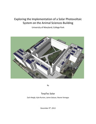
Centered at coordinates 38.991675,
-76.939472 [2], it receives 4.36 kWh/m2/day
of solar radiation [3]. The combined usable
rooftop area is estimated via satellite
imagery to be approximately 65,000 ft2 [3].
Potential solar photovoltaic (PV) arrays are
considered for the east, west, and south
rooftops of the ANS building. Its annual
electricity consumption is estimated to be
4,963,481 kWh/yr, a calculation further
explained later in this report.
Fig. 1: Aerial view of the Animals Sciences building](data:image/gif;base64,R0lGODlhAQABAIAAAAAAAP///yH5BAEAAAAALAAAAAABAAEAAAIBRAA7)
Recommended
More Related Content
What's hot
What's hot (20)
Similar to Final Report - PV Group ANS
Similar to Final Report - PV Group ANS (20)
Final Report - PV Group ANS
- 1. Exploring the Implementation of a Solar Photovoltaic System on the Animal Sciences Building University of Maryland, College Park By TerpTec Solar Zach Neigh, Kyle Runion, Jaime Salazar, Reane Venegas December 9th, 2013
- 2. Exploring the Implementation of a Solar Photovoltaic System on the Animal Sciences Building The Animal Sciences building is an energy-intensive component of the University of Maryland, College Park campus. It operates several offices, classrooms, and laboratories for much of the day, if not through its entirety. Separated into various roof sections, its combined roof area is approximately 65,000 ft2 . This solar photovoltaic design aims to offset an estimated electric usage of 4,963,481 kWh/yr. The system consists of 479 solar panels, a ballasted mounting system, 14 central inverters, and other components of a typical solar array. The panels are tilted at 10 degrees and face south to maximize sunlight absorption. Materials are sought for their American origins and the market is surveyed for the most economic supplier. As a grid-tied system, no battery is required, although the electricity ‘sell-back’ scheme will not likely be extensively used, as not much excess electricity generation is expected. At a cost of between $1.05 and $1.62 per Watt installed and a discounted levelized cost of $0.09 and $0.13 per kWh of electricity generated, the system is expected to compete economically with the University’s conventional electricity sources only if given sufficient incentives and funding, namely, those from the University Sustainability Fund. However, the return-on-investment is achieved quickly in the first 4 to 6 years, again depending on the grant awarded, and a year-by-year analysis details the varying electricity retail rates, the expected electricity generation, and other factors that come into play during the 25-year lifetime of the system. Overview of the Client The University of Maryland, College Park (UMD) campus consumed 209,455 MWh in 2012, of which 12,643 MWh came from renewable sources [1]. Located off of Regents Drive within the campus, the Animal Sciences (ANS) building is targeted because of its relatively high consumption, due to the large laboratory space, and its current lack of any renewable energy systems. Centered at coordinates 38.991675, -76.939472 [2], it receives 4.36 kWh/m2/day of solar radiation [3]. The combined usable rooftop area is estimated via satellite imagery to be approximately 65,000 ft2 [3]. Potential solar photovoltaic (PV) arrays are considered for the east, west, and south rooftops of the ANS building. Its annual electricity consumption is estimated to be 4,963,481 kWh/yr, a calculation further explained later in this report. Fig. 1: Aerial view of the Animals Sciences building
- 3. Renewable Energy Technology General description of the technology Solar PV technology absorbs the light energy from the sun and converts it directly to electricity. Figure 2 illustrates the basic energy flow and different components of a PV cell. The cover glass and anti-reflective coating helps to maximize sunlight absorption to provide the energy needed to excite electrons in the p-n junction. These electrons then move to through the front contact and substrate, generating an electrical current. Individual cells are interconnected and arranged in modules and arrays to achieve the desired power supply generation [4]. Energy production depends on factors such as hardware efficiency, insolation, microclimate, azimuth angle (e.g., S, SE or SW), shading, and the tilt angle [5]. Solar arrays should face South or near-South titled at an angle comparable to the latitude of the site, ideally also varying with the season [6]. For instance, a lower tilt during the summer will allow the panels to receive sunlight at a more perpendicular angle from the Sun, which is higher in the sky during those months. In PV cells, silicon is the primary non-metallic material used as a semiconductor, that is, a material sharing some of the properties of metals and those of electrical insulators. The addition of trace amounts of impurities, a process known as doping, creates two semiconductor layers within the cell, a positive (p-type) and negative (n-type) layer, increasing its conductivity. In p- type semiconductors, atoms containing fewer electrons, such as boron (with only three valence electrons) are doped to silicon. Therefore, only three covalent bonds are formed. The boron atom is missing the last electron needed for the fourth covalent bond with any adjacent silicon. The missing electrons are referred to as holes and are considered equal to a positively charged particle [6]. This process creates a region with an excess of positively charge carriers and a negatively charged impurity atom [7]. In n-type semiconductors, atoms containing more electrons are added to silicon. Phosphorous is often used as an n-type impurity because of its five Fig. 2: Components of PV cell. Source: NREL
- 4. valence electrons. Only four of these electrons are tied up with those from the silicon atoms. The fifth, non-bonded electron can move freely within the silicon lattice, creating a region filled with negatively charged carriers and a positively charged impurity atom [7]. The p-n junction is created when both layers are joined together. In the p-type region, holes diffuse to the n-type region and pair up with electrons. Meanwhile, the electrons diffuse from the n-type region to the p-type region to join with holes. The diffusion of carriers leaves the static-charged impurities in the junction. For instance, negatively charged boron is found in the p-type junction, while positively charged phosphorus is left behind in the n-junction. Eventually, the diffusion process creates a depletion zone where charge carriers are no longer present. This region is also known as the electric field, which is the main component providing the voltage needed to drive the electrical current. Photovoltaic cells are able to generate electricity from photons, or light energy, because p-type and n-type semiconductors consist of a conduction band, valence band, and energy band gap. The energy band gap is the energy, expressed in electron Volts (eV), required to promote an electron in the conduction band. Silicon has a band gap of 1.1 eV, but well-suited PV cell semiconductors range from 1.0 eV to 1.9 eV [6]. When ample photon energy reaches the p-n junction, it generates new electron-hole pair carrier charges. Covalent bonds are broken and electrons are stimulated. The excited electron moves up to the conduction band and travels to the n-type region. The new hole created in the absence of electrons moves down to the valence band and through the p-type region. The electrons and holes move in opposite directions and travel through an external circuit to create electrical current. Along with the voltage already existent in the electric field, this current allows for power generation from the cells. Applications of the technology PV systems may be grid-connected or off-grid. Grid-connected systems use an inverter to transform the direct current (DC) to alternating current (AC) load, the type used by most household appliances. The electricity generated is connected to the grid network as an additional energy source. Often, excess energy can be sold back to the utility company. These systems are commonly constructed on residential and commercial rooftops, although ground-mounted and utility-scale arrays are also notable applications. In off-grid systems, charge controllers and battery banks are used to collect DC loads. These are more popular in rural areas with limited grid connections because they help produce electricity to meet basic energy needs [8]. DC can be directly used in DC systems without an inverter as well. Advantages of the technology Solar energy provided less than 0.1% of the electricity demand in the United States in 2010 [9]. However, the market has been growing, strongly linked to research into lowering costs and increasing the efficiencies PV cells. Also underway is the appearance of cheaper semiconductors and the invention of thin film technology using amorphous silicon, copper indium (gallium) diselenide, and cadmium telluride [6]. Local, state, and federal governments also offer rebates and tax credits to incentivize the solar energy market.
- 5. PV technology costs ranged from $4 to $6 per Watt (W) for utility-scale and commercial projects in 2010 [9]. According to the Solar Energy Industries Association (SEIA), the average PV panel price dropped more than 60% from 2010 values, reducing the installed system price to $3.05 per Watt (figure 3) [10]. The decline in prices are also associated with the dramatic increase in installed energy capacity over the last few years (figure 4). The distribution loss is also reduced because the system is constructed where the energy will be used. PV systems are a prime example of a sustainable technology. The emissions from their manufacturing, construction, and transportation stages are very low compared the coal industry. The Intergovernmental Panel on Climate Change estimates about 0.07 to 0.18 pounds of carbon dioxide per kilowatt-hour originating from PV, approximately 5% of the emissions from coal- sourced electricity (1.4-3.6 lbs CO2/kWh) [11]. Additionally, land use issues are mitigated because most systems are installed on rooftops. Since typical modules are stationary, there are no moving parts and noise pollution is eliminated as well. Motion-tracking devices are sometimes used to adjust the panels’ tilt angle but their movement is too minimal to produce any harmful impact. Disadvantages of the technology Despite the module cost reductions in the past few years, the balance of system (BOS) costs has not yet followed this trend. The BOS consists of hard costs (inverters, structure, wiring, and equipment) and soft costs (design, engineering, and permits) that add approximately $1/W to $4/W depending on the system size and location [4]. Output fluctuation is also a problem, due to varying seasonal and daily conditions, as PV systems cannot produce electricity at nighttime. Furthermore, the technology only has an average lifetime of 20-25 years and 20 percent efficiency [12]. Therefore, few units can completely rely on solar power to meet their energy needs, which would require a significantly large and expensive battery-backed system as well as further enhancements in efficiency. Finally, traces of potent greenhouse gases and metals are found in PV cell manufacturing as well. Lead, cadmium, and silicon tetrachloride are some of the wastes that need proper handling and disposal to prevent pollution in air, water, and land resources [13]. Fig. 3: Decline in system price. Source: SEIA Fig. 4: Current and projected US installed capacity. Source: SEIA
- 6. Renewable Energy System Design The system designed for this project is a 131.7-kW system made up of 479 Sunmodule Plus 275 W mono panels, IronRidge ballast mounting trays, and 14 Sunny Boy 8000 inverters (for a complete list of materials, see Table 1, Appendix B; close-ups of the designed 3D model are visible in the Appendix A). The ANS building has multiple roofs with varying heights, but can be divided into the North, East, West and South roofs. Figure 5 displays the layout of the 15 solar arrays. Each panel will have a 10-degree tilt, an angle fixed by the mounting system manufacturer [14]. Although a 10° tilt is lower than the ideal latitude-equal tilt used in other applications, the lower space and shading requirements compensate for this in large, commercial-scale systems [15; 16]. Additionally, each array will face south (a 180-degree azimuth) to maximize Sun exposure. SolarWorld is an American manufacturer [17] and, as a public university, UMD should support the domestic solar industry. Although most large scale projects use panels rated at 300 W or above, SolarWorld offers a maximum of 275 W. Each panel is composed of 60 cells, for a total dimension of approximately 3 ft x 5 ft x 1.2 in, and has an efficiency of 16.4% [17]. There is a maximum performance degression of 0.7% per year and a general warranty for 10 years [17]. A fair compromise is struck between the higher cost of monocrystalline panels and their higher quality and efficiency. A ballasted racking system is chosen because rails and beams cannot safely span the range of widths of the different roof sections and provide support for the designed array sizes. Instead, each non-penetrating “tray” will support their respective panels, ensuring the structural integrity Fig. 5: Location of inverters.
- 7. of these essentially self-supporting units while minimizing alterations to the existing structure [14]. The ballasted roof mount system (figure 9, App. A) from IronRidge comes pre-assembled, reducing installation costs. This racking system is fairly versatile, designed to withstand wind speeds up to 140 mph and up to 5o of allowable slope roof [16]. With near hurricane-strength winds in the mid-Atlantic, this robustness is vital. An all-metal construction ensures strength and durability over the system lifetime. This is especially impressive considering its roof loading weight as low as 2.8 lbs/ft2 [18]; with such a large system, distributing weight is important for roof stability. A total of 14 SMA Sunny Boy 8000-US central inverters will be located in groups meant to sufficiently service, in terms of wattage, the various arrays on the different roof sections of the building (figure 5). With central inverters, the use of 479 microinverters, independently installing one on each panel, is an easy issue to avoid and drastically cuts down on materials and installation costs. The advantage of using microinverters, more common in residential installations, lies in their ability to allow each panel to independently operate such that a malfunction or shading on a one section of the array will not bring down the entire system. These SMA central inverters enjoy 97% peak efficiency, which will help optimize energy production, and automated grid voltage detection, which can help with any troubleshooting and maintenance of the system [19]. These American-made inverters come with a 10-year warranty [19]. The system will be grid-tied. Batteries that store produced energy may be beneficial when excess production is expected. However, it is unnecessary in the case of the ANS building, with its multiple offices, classrooms, and, most importantly, laboratories running most hours of the day and making it a significant amount of excess power production unlikely, especially at the high cost of battery systems. Instead, this excess is automatically sold back to the grid and retrieved when necessary, effectively rendering the grid as a personal battery system. This money earned back from the utility company will help to pay back some of the initial costs of the system. Payback Period Costs Various online wholesale suppliers offer SolarWorld 275-W modules for $1.15/W [20], $1.36 [21], and $1.50/W [22]. Though shipping costs are not usually readily displayed, freecleansolar.com quotes a final price of $1.64/W, including shipping. Based on this additional $0.14/W TerpTec Solar will quote the client at $1.30/W per module from the cheaper wholesaler, or $357.50 per module. SMA Sunny Boy 8000-US central inverters are found on the market each for $3234.00 [23], $2699.00 [24], and for an average of $3239.00 [25]. United Parcel Service’s (UPS) online shipping calculator provides ground freight rates between Newark, NJ and College Park, MD that raise the total to approximately $3296 per inverter. A New Jersey location is chosen because of its abundance in distributor and trucking entities. TerpTec Solar will absorb the higher shipping costs due to a different origin location, though these will likely be partially compensated by the shipping rate of the inverter supplier as opposed to a third party such as UPS.
- 8. The Iron Ridge ballasted mounting system consists of trays, blocks, clamps, wind deflectors, and cement blocks. For each array, the number of trays, t, depends on the number of rows, r, in the given array and the number of panels, p, in each row such that t = (r + 1) x (p + 1). Each tray is held down by 4 blocks, while each panel requires 4 clamps to be secured onto a tray, with 1 wind deflector per module and 1 grounding lug per row. Altestore.com is chosen because they deliver these 4 components pre-assembled, reducing installation time and, therefore, cost [14]. Individual prices for each item from this wholesaler are detailed in the Table 1 (App. A). Labor, in terms of construction and electrician work, hovers around 3.75 man-hours per panel for the United States [26] and around 3.2 man-hours per panel for a solar installer in the District of Columbia [27], resulting in 3.5 man-hours per pane as a reasonable estimate for this project. At an hourly rate of $25 per man-hour, TerpTec Solar estimates $87.50 per panel installed. Maintenance and service is provided to the client free of charge. Other items are given rough figures to broadly secure their funding while in reality these numbers are dealt with internally within TerpTec Solar. A 6% sales tax is included to the cost of the system solely to help visualize and strengthen awareness of the sales tax exemption detailed below. Incentives and Savings Section 48 of the Internal Revenue Code grants a federal tax rebate for a value of 30% of the total system cost [28]. With no maximum awarded, the only exemptions concern passive solar and solar pool heating systems. The rebate is applied at the end of the year in which the project is completed. The Maryland Tax - General Code, Section 11–230, sales and use tax is not applied to the sale of solar equipment [29]. The House Bill 1198 of the Maryland General Assembly grants up to 15% of the system cost against state income tax for the year during which the system is placed in service [30]. According to the Maryland Tax Code Section 10-720, the Clean Energy Production Tax Credit of 2006 grants $0.0085 per kWh of electricity produced by the system [31]. Though it based on the actual electricity generation, the analysis utilizes the estimated production. The University of Maryland Sustainability Fund awarded an average of $29,000 for 17 projects, with the top three receiving $84,000, $93,000, and $96,000 for the 2012-2013 year [32]. In 2010-2011, an educational solar array received $30,000 [32]. The Fund has announced $350,000 available for the 2013-2014 year [33]. Because this project aligns very closely with the ideals and criteria of the Sustainability Fund – a connection to campus, innovation, a cost/benefit analysis, environmental benefits, accountability, metrics, self-sufficiency, and a clear potential for broad application [34] – an award of $30,000 is considered likely, with a strong chance of receiving a much larger quantity. Therefore, varying scenarios dependent on the final award amount are considered.
- 9. Yearly Expenses and Savings The annual electricity consumption is 4,963,481 kWh/yr. This is calculated using Google SketchUp’s area tool, yielding a total building area of 72745.6199 ft², and the average electricity consumption for a university laboratory of 734.43 kWh/m2/yr [35] or 68.23 kWh/ft2/yr. The Public Service Commission of Maryland’s Renewable Energy Portfolio Standard Report of 2007 mandates a minimum amount of a utility company’s electricity generation from renewable energy sources [36]. Section 7-701 of the Maryland Public Utility Companies Code allows for the establishment of a market for Solar Renewable Energy Credits (SRECs) in the state [37]. As in any market, SRECs prices may rise and fall with time, having hovered around $0.13/kWh in 2013 and peaking at $0.138/kWh by November 2013 [38]. The electricity generation is calculated with PVWatts Version 1, an online tool developed by the National Renewable Energy Laboratory (NREL) [39]. A DC-rated 131.7 kW system in the city of Baltimore, the closest point to College Park available in the tool (receiving a similar insolation value of 4.36 kWh/m2/day), oriented south and tilted at 10°, with an overall derate factor of 0.77 is calculated to produce 150,408 kWh (AC) per year. The derate factor, an average figure provided by the NREL, takes into account the typical efficiency losses for each element such as the modules, the inverters, and the wiring. Any electricity generated in excess is directed back into the grid and assessed as a credit by the utility company, effectively converts the regional grid a battery that is readily available to the client at any moment. This framework is established by the Public Utilities Article Section 7- 306 [40], which fixes this ‘sell back’ rate equal to the retail rate. The 2-MW cap does not pose an issue to this 131.725-kW system. Return-on-Investment (ROI), Price per Watt Installed, and Yearly Analysis The ROI is calculated as the net one-time cost (the one-time expenses such as the materials cost and labor cost minus one-time discounts such as the federal, state, or university incentives) divided by the net yearly savings (the annual SRECs income and the annual electricity production). Depending on the varying amounts awarded by the University of Maryland Sustainability Fund, an ROI of 4-6 years is expected (Table 3, App. B), an attractive figure compared to the 5-10 years projected by other Maryland contractors such as SolarCity [41] and market evaluators Solarbuzz [42]. The final price per Watt installed is calculated as the net one-time cost divided by the system size (131,725 W). This final figure ranges between $1.05/W and $1.62/W depending on the amount awarded by the UMD Sustainability Fund. Compared to the national average of $3.71/W for non-residential systems and lower bound of $2.00/W [43], this project is an economically attractive investment for the University. The discounted annual levelized costs is calculated for a real discount rate of 8% - as various solar projects have used figures such as 8% [44], and 8.1% [45] - over 25 years, the lifetime of the system, resulting in annual repayments of $94 on $1000 of capital cost. For example, for the first scenario, the initial capital cost of $213,816.56 yields an annuitized value of the capital
- 10. cost of $213,816.56 / $1000 x $94 = $20,098.76 per year. This value is divided by the annual electricity generation to yield an electricity cost of approximately $0.13 per kWh generated by the system. This is calculated for the remaining three scenarios as well, reaching figures as low as $0.09/kWh (Table 3, App. B), compared with their current rate of $0.11/kWh [46]. Depending on the fuel source, electricity retail rates increase yearly by 2.3%, 2.7%, 2.4%, 3.2%, and 1.9% for propane, distillate fuel oil, residual fuel oil, natural gas, and electricity, respectively [47], resulting in the 2.5% yearly increase used in this report. The module performance degression of 0.7% per year is given by the manufacturer [48]. The SREC rates cannot be accurately projected over 25 years as policy simply determines their maximum price while the market dictates their actual, highly fluctuating prices. For example, though rates have been capped at $0.40/kWh for the past few years, market prices in Maryland have hovered around half to a third of this value in 2012, dropping to around $0.14/kWh in 2013 [38]. Therefore, conservative projected rates will consist of one third of the cap for any given year [38]. Tables 4a and 4b (App. B) and figure 10 (App. C) display the different components of the analysis as they vary through the years. Final Recommendation The cost-effectiveness of this investment is significant only in the case of receiving strong funding from the UMD Sustainability Fund (e.g., scenarios 3 and 4). Otherwise, differences in the ultimate price paid for the electricity generated are relatively minimal or even unfavorable to this acquisition. Though the PV system can be sold for a low price per Watt, the amount of electricity it generates is not likely to make a significant contribution to the overall consumption of such an energy-intensive building. However, even if the system were to ultimately result in no monetary savings, the fact that a portion of this building’s electricity now originates from renewables may be incentive enough for the University. Granted, the analysis has been hindered by certain limitations. First, roof access was not available and so field measurements were completely substituted with estimations based on aerial views. Because certain features like vents, appliances, and any other rooftop obstacles cannot be accurately located, the system was designed conservatively in terms of size. It is possible that a larger system will generate higher savings and revenue to more significantly shift the figures to its favor. Clearly, a real-life proposal would be accompanied by an on-site assessment of the project area. In addition, a study of the roof’s loading capacity would be necessary. Second, material prices were strictly sought from online websites, where unit prices were presented regardless of the order size, whereas requesting a quote from the supplier would likely yield unit prices that decrease with order size, i.e., the advantage of bulk purchases. Also, as mentioned, shipping fees were not always readily available and had to be estimated. Furthermore, material prices may vary from the time of writing to their actual acquisition. Third, many figures used in this report are estimates (e.g., the electricity generation) while certain incentive programs will reward based on realized (and oftentimes lower) production. The electricity consumption was calculated as opposed to handed to the contractor, as most easily receive the client’s electric bill for a real-life project. Other figures are projected over 25 years (e.g., electricity retail rates), consist of erratic market values (e.g., SRECs), or combinations of all
- 11. of these types. For example, the University is said to be charged at around $0.11/kWh for its energy use although this varies depending on its source (e.g., natural gas or the campus power plant). Even small inaccuracies compounded on each other or held over large system sizes or time spans may noticeably add up and skew the final numbers. Fourth, the IronRidge brand of ballasted system fixes the tilt angle at 10o. A relatively simple model for varying tilt angles and row spacings could help determine the proper compromise between system size and sunlight exposure to maximize generation. Fifth, a more in-depth review of the incentives may reveal restrictions or ineligibilities that may raise what may be admittedly an overly optimistic net system cost, as it is not usual for a system to be marked down by 65%-70% due to savings. Sixth, no mention of the monitoring software has been made although clients usually like having this at their disposal. Finally, an exploration of the potentially different contract types is missing such as a lease option in which the system is installed for free while the contractor retains all of the SRECs. Team Contribution Zach completed the ‘Client Overview’. This mainly involved preliminary research and research on the electrical consumption. After experiencing difficulties getting an electricity consumption report from the university, alternative methods of estimating the consumption were used which in total took about 4 hours. About 2 hours were spent getting building specifics and estimating the usable roof area as well as calculating the solar insolation that would fall on our system. Another hour was spent meeting with facilities management. The total time contributed is 7 hours. Jaime compiled the ‘Payback Period’ section. This involved researching the materials concurrently with Kyle and, specifically, browsing online wholesalers to find out prices and estimating shipping costs from a third-party service. Other research concerned the labor requirements, the legislation, the Sustainability Fund, the total consumption, and the estimated electricity generation. In addition, projections had to be found for the SREC prices, the electricity retail prices, and the module performance degression. Overall, the research portion required approximately 6 hours of work. This then allowed Jaime to calculate the ROI, the price per Watt, and the discounted annual levelized cost per kWh as well as to create their corresponding tables and graphs during 1 hour of work. Another large portion of the project was dedicated to modeling the system on Google SketchUp based on racking dimensions taken from the manufacturer’s datasheet and on building dimensions derived from Google Maps and Bing. The system design took approximately 4 hours. From the model, the relationship between the number of panels and the number of racking units could be calculated. The meeting with Facilities Management along with taking part in other sections such as the ‘Final Recommendation’ and ‘Executive Summary’ bring the total time dedicated to this project to approximately 12 hours. Kyle completed the Renewable Energy System Design. This involved preliminary research, selection of materials and research of the client. The preliminary research of solar PV designs, limitations, and efficiencies took about 2 hours. The selection of materials was completed jointly with Jaime. Along with the research on these technologies, 3 hours were spent. Another hour
- 12. was spent meeting with facilities management, and 2 hours were spent researching the client for certain system designs. The total time contributed is 8 hours. Reane provided the general description of the technology. He performed research using online databases, renewable energy textbooks, and case-study reports. He also watched instructional videos and searched articles on the web relating to solar energy. These tasks provided support for the statements and statistical numbers used in the background portion of the paper. The research portion took approximately 6 hours to compile and organize. Another 2 hours are spent finalizing the background content, final recommendations, and the references used. All group members also spent 1 hour meeting with facilities management and taking pictures of the roof. The total amount of hours contributed was 9 hours.
- 13. References 1: “Sustainability Progress Report 2013.” University of Maryland. n.d. Web. 18 Nov 2013. <http://www.sustainability.umd.edu/documents/Reports/Sustainability%20Progress%20Report2013_web.pdf>. 2: “Google Maps.” Google. n.d. Web. 16 Nov 2013. <http://maps.google.com>. 3: US Solar Radiation Maps. National Renewable Energy Laboratory. n.d. Web. 16 Nov 2013. <http://rredc.nrel.gov/solar/old_data/nsrdb/1961-1990/redbook/atlas/Table.html>. 4: Drury, E.; Margolis, R.; Denholm, P.; Goodrich, A.C.; Heath, G.; Mai, T.; Tegen, S. (2012). "Solar Energy Technologies," Chapter 10. National Renewable Energy Laboratory. Renewable Electricity Futures Study, Vol. 2, Golden, CO: National Renewable Energy Laboratory; pp. 10-1 – 10-60. Web. 12 Nov. 2013 <http://www.nrel.gov/docs/fy12osti/52409-2.pdf>. 5: Edoff, Marika. "Thin Film Solar Cells: Research in an Industrial Perspective." The Royal Swedish Academy of Sciences 41.2 (2012): 112-18. The Royal Swedish Academy of Sciences, 2012. Web. Nov. 2013. <http://search.proquest.com/engineeringcollection/docview/963513855/141BE45EE9B554818B7/1?accountid=14 696>. 6: Boyle, Godfrey. Renewable energy: power for a sustainable future. 3rd ed. Oxford: Oxford University Press, 2012. Print. 7: Sproul, Allstair. "Understanding p-n junction." University of Southern Wales. Web. 12 Nov 2013. <http://www2.pv.unsw.edu.au/nsite-files/pdfs/UNSW_Understanding_the_p-n_Junction.pdf>. 8: Rolland, Simon. Rural Electrification with Renewable Energy. Publication. Brussels: Alliance for Rural Electrification, 2011. Web. 12 Nov 2013. <http://www.ruralelec.org/fileadmin/DATA/Documents/06_Publications/ARE_TECHNOLOGICAL_PUBLICATION.pdf >. 9: Sun Shot Vision Study. Publication. United States Department of Energy, 2012. Web. Nov. 2013. <http://www1.eere.energy.gov/solar/pdfs/47927.pdf>. 10: "Solar Energy Facts: Q2 2013." Solar Energy Industries Association. Solar Energy Industries Association, 2013. Web. 13 Nov 2013. <http://www.seia.org/sites/default/files/Q2%202013%20SMI%20Fact%20Sheetv2.pdf>. 11: "Environmental Impacts of Solar Power." Union of Concerned Scientists. Union of Concerned Scientists, 3 Feb. 2013. Web. 13 Nov. 2013. <http://www.ucsusa.org/clean_energy/our-energy-choices/renewable- energy/environmental-impacts-solar-power.html>. 12: Hahn, Giso. "Solar Cells from Ribbon Silicon." Renewable Energy: Sustainable Concepts for the Energy Change. Weinheim: Wiley-VCH, 2013. 44-51. Print. 13: "What Is the Environmental Impact of Photovoltaic (PV) Solar Panels?" CAT Information Service. Centre for Alternative Technology, n.d. Web. 04 Dec. 2013. <http://info.cat.org.uk/questions/pv/what-environmental-impact- photovoltaic-pv-solar-panels>. 14: “IronRidge Ballast Mount Tray” AltEStore, n.d. Web. 15 Nov 2013. <http://www.altestore.com/store/Solar- Panel-Mounts-Trackers/Roof-Mounts-for-Solar-Panels/Ballasted-Roof-Mounts/IronRidge-Ballast-Mount-Tray-10- degree/p10242/>. 15: Brooks, William, and James Dunlop. NABCEP Photovoltaic (PV) Installer Resource Guide. Rep. National American Board of Certified Energy Practitioners, Mar. 2012. Web. 5 Dec. 2013. <http://www.nabcep.org/wp- content/uploads/2012/08/NABCEP-PV-Installer-Resource-Guide-August-2012-v.5.3.pdf>. 16: Stafford, Byron. Commercial Scale PV Systems. Rep. National Renewable Energy Laboratory, June 2006. Web. 5 Dec. 2013. <http://apps1.eere.energy.gov/tribalenergy/pdfs/course_solar_stafford.pdf>.
- 14. 17: "Sunmodule Plus SW 275 Mono." SolarWorld-USA. SolarWorld, n.d. Web. 15 Nov 2013. <http://www.solarworld-usa.com/~/media/www/files/datasheets/sunmodule-plus/sunmodule-solar-panel-275- mono-ds.pdf>. 18: "Ballasted Roof Mounting Tech Specs." IronRidge, n.d. Web. 15 Nov 2013. <http://www.ironridge.com/products/ballastedroofmounting/techspecs>. 19: "Sunny Boy 5000-US / 6000-US / 7000-US / 8000-US." SMA-America. SMA Solar Technology, n.d. Web. 15 Nov 2013. <http://www.sma-america.com/en_US/products/grid-tied-inverters/sunny-boy/sunny-boy-5000-us-6000- us-7000-us-8000-us.html>. 20: “SolarWorld SW 275-BAA 275W Mono SLV/WHT US Solar Panel.” CivicSolar, n.d. Web. 8 Dec. 2013. <http://www.civicsolar.com/product/solarworld-sw275-baa-275w-mono-slvwht-us-solar-panel>. 21: “Solar World Modules – Mono.” Inter-Island Solar Supply, n.d. Web. 8 Dec. 2013. <http://solarsupply.com/products/SOLARPV/SOLARMOD/24%20VOLT%20PV%20MODULES.aspx>. 22: “SolarWorld PV Modules.” FreeCleanSolar, n.d. Web. 15 Nov 2013. <http://www.freecleansolar.com/SolarWorld-Solar-Panels-s/70.htm>. 23: “SMA Solar Technology.” Wholesale Solar, n.d. Web. 15 Nov 2013. <http://www.wholesalesolar.com/products.folder/inverter-folder/SB8000US.html>. 24: “SMA Sunny Boy 8000 US Solar Inverter with Fused DC Disconnect.” Amazon, n.d. Web. 8 Dec. 2013. <http://www.amazon.com/Sunny-Boy-8000-US- Disconnect/dp/B008OKTRIO/ref=sr_1_fkmr0_2?ie=UTF8&qid=1386546091&sr=8-2- fkmr0&keywords=sunnyboy+sma+8000>. 25: Ebay, n.d. Web. 8 Dec. 2013. <http://www.ebay.com/sch/i.html?_sacat=0&_from=R40&_nkw=sma%20sunny%20boy%208000&_fscr=1>. 26: Aarre Maehium, Mathias. The Homeowner's Guide to Solar Panels. Rep. Energy Informative, 14 Aug. 2013. Web. 21 Nov. 2013. <http://energyinformative.org/solar-panels-installation-time>. 27: Kiarash, Atta. Solar Solution. Personal Interview. Summer 2013. 28: Title 26, Section 48, Internal Revenue Code. Rep. U.S. Government Printing Office, n.d. Web. 5 Dec. 2013. <http://www.gpo.gov/fdsys/pkg/USCODE-2011-title26/pdf/USCODE-2011-title26-subtitleA-chap1-subchapA- partIV-subpartE-sec48.pdf>. 29: Section 11-230, Article Tax General. Rep. Maryland General Assembly, n.d. Web. 5 Dec. 2013. <http://167.102.242.144/search?q=cache:fHbDauLTAscJ:mgaleg.maryland.gov/google_docs%24/2013rs/statute_g oogle/gtg/11- 230.pdf+solar+tax&site=all&client=mgaleg_default&proxystylesheet=mgaleg_default&output=xml_no_dtd&ie=UT F-8&num=100&access=p&oe=UTF-8>. 30: Section 10-719, House Bill 1198. Rep. Maryland General Assembly, n.d. Web. 5 Dec. 2013. <http://167.102.242.144/search?q=cache:fHbDauLTAscJ:mgaleg.maryland.gov/google_docs%24/2013rs/statute_g oogle/gtg/11- 230.pdf+solar+tax&site=all&client=mgaleg_default&proxystylesheet=mgaleg_default&output=xml_no_dtd&ie=UT F-8&num=100&access=p&oe=UTF-8>. 31: Clean Energy Production Tax Credit (Personal). Rep. Database of State Incentives for Renewables & Efficiency, 25 June 2013. Web. 5 Dec. 2013. <http://www.dsireusa.org/incentives/incentive.cfm?Incentive_Code=MD17F&State=federal%C2%A4tpageid=1&ee =1&re=1>.
- 15. 32: Grant Recipients. Rep. University Sustainability Fund, n.d. Web. 5 Dec. 2013. <http://www.sustainability.umd.edu/content/about/fund_recipients.php>. 33: Overview. Rep. University Sustainability Fund, n.d. Web. 5 Dec. 2013. <http://www.sustainability.umd.edu/content/about/fund.php>. 34: Project Criteria. Rep. University Sustainability Fund, n.d. Web. 5 Dec. 2013. <http://www.sustainability.umd.edu/content/about/fund_criteria.php>. 35: Hopkinson, Lisa, Peter James, Nigel Lenegan, Tom McGrath, and Malcom Tait. Energy Consumption of University Laboratories: Detailed Results From S-Lab Audits. Rep. Higher Education for Environmental Performance Improvement, July 2011. Web. 5 Dec. 2013. <http://www.goodcampus.org/files/files/60-S Lab_Energy_Audits_of_HE_Labs_final_v15_4_7_11.pdf>. 36: Renewable Energy Portfolio Standard Report of 2007. Rep. Public Service Commission of Maryland, Feb. 2007. Web. 5 Dec. 2013. <http://webapp.psc.state.md.us/intranet/Reports/RenewablePortfolioStandardReport_2007.pdf>. 37: Section 7-701, Article Public Utilities. Rep. Maryland General Assembly, n.d. Web. 5 Dec. 2013. < http://mgaleg.maryland.gov/2014rs/statute_google/gpu/7-701.pdf>. 38: Maryland SREC Market. Rep. SRECTrade, n.d. Web. 5 Dec. 2013. <http://www.srectrade.com/maryland_srec.php>. 39: "PVWatts Site Specific Data Calculator.” NREL: PVWatts Site Specific Data Calculator (Version 1). National Renewable Energy Laboratory, n.d. Web. 15 Nov 2013. <http://www.nrel.gov/rredc/pvwatts/site_specific.html>. 40: Section 7-306, Article Public Utilities. Rep. Maryland General Assembly, n.d. Web. 5 Dec. 2013. <http://mgaleg.maryland.gov/2014rs/statute_google/gpu/7-306.pdf>. 41: What Is Solar Energy - Solar Energy Pros and Cons. SolarCity, n.d. Web. 05 Dec. 2013. <http://www.solarcity.com/learn/solar-faqs.aspx>. 42: Economic Payback. Solarbuzz, n.d. Web. 05 Dec. 2013. <http://www.solarbuzz.com/going- solar/using/economic-payback>. 43: Solar Market Insight Report 2013 Q2. Solar Energy Industries Association, n.d. Web. 05 Dec. 2013. <http://www.seia.org/research-resources/solar-market-insight-report-2013-q2>. 44: Valuing the Return on Solar Projects for Businesses and Government Agencies. Sunpower Corporation, Feb. 2011. Web. 5 Dec. 2013. <http://us.sunpowercorp.com/cs/Satellite?blobcol=urldata&blobheadername1=Content- Type&blobheadername2=Content-Disposition&blobheadervalue1=application/pdf&blobheadervalue2=inline; filename=Valuing+the+Return+on+Solar+Projects+for+Businesses+and+Government+Agencies.pdf&blobkey=id&bl obtable=MungoBlobs&blobwhere=1300258523799&ssbinary=true>. 45: Solar Perspectives: What Is Inside Your LCOE Assumptions? SolarServer, 11 Mar. 2010. Web. 05 Dec. 2013. <http://www.solarserver.com/solar-magazine/solar-point-of-view/solar-point-of-view/solar-perspectives-what-is- inside-your-lcoe-assumptions.html>. 46: Stewart, Mark. Office of Sustainability. 26 Nov. 2013. 47: Table A3: Energy Prices by Sector and Source. Energy Information Administration, n.d. Web. 5 Dec. 2013. <http://www.eia.gov/forecasts/aeo/er/pdf/tbla3.pdf>. 48: Installation Manual 2013 Edition V2.3. IronRidge, n.d. Web. 5 Dec. 2013. <http://www.ironridge.com/files/ballastedmounting/IronRidge_BallastedRoofMount_InstallationManual.pdf>.
- 16. Appendix Appendix A: Figures Fig. 6: A proposed site for a solar array. Fig. 7: Aerial view of the 3D model of the complete system.
- 17. Fig. 8: Close up of the northeastern (top) and southwestern (bottom) roof sections.
- 18. Fig. 9: 3D model of the ballasted mounting and modules. The slight Sun-facing tilt (left) and wind deflectors (right) are visible at this scale.
- 19. Appendix B: Tables Table 1: Estimates ITEM UNIT VALUE UNIT QTY. VALUE COSTS Materials SolarWorld Sunmodule Plus 275W Mono $357.50 module 479 $ 171,242.50 Iron Ridge Ballast System - Trays $52.65 tray 699 $ 36,802.35 Iron Ridge Ballast System - Wind Deflector $52.46 deflector 479 $ 25,129.05 Iron Ridge Ballast System - Clamps $4.10 clamp 2796 $ 11,463.60 Iron Ridge Ballast System - Grounding Lugs $6.00 lug 88 $ 528.00 Concrete Blocks $0.55 block 2796 $ 1,537.80 SMA Sunny Boy 8000-US $3,239.00 inverter 14 $ 45,346.00 Other (ties, cables, bolts, conduits, etc.) - - - $ 8,000.00 Labor Installation (Set Up Crew, Electricians) $87.50 module 479 $ 41,912.50 Engineering Service - - - $ 10,000.00 Overhead and Profit (25%) - - - $ 87,990.45 Tax (6%) - - - $ 26,397.14 Total $ 466,349.39 SAVINGS Federal Incentive 30% Tax Credit - - - $ 139,904.82 Sales Tax Exempt - - - $ 26,397.14 State Incentives 15% State Income Tax Credit - - - $ 69,952.41 Clean Energy Production Tax Credit $0.0085 kWh 150408 $ 1,278.47 UMD Sustainability Fund Lower Bound $ 15,000.00 Medium $ 30,000.00 Medium-High $ 60,000.00 Upper Bound $ 90,000.00 Total Scenario 1 (low Sustainability award) $ 252,532.83 Scenario 2 (med. Sustainability award) $ 267,532.83 Scenario 3 (med.-high Sustainability award) $ 297,532.83 Scenario 4 (high Sustainability award) $ 327,532.83
- 20. Table 2: Yearly Expenses and Savings ITEM RATE QTY. YEARLY EXPENSES Electricity Consumption $0.11 $/kWh 4963481 $ 545,982.90 YEARLY SAVINGS SRECs Income $0.13 $/kWh 150408 $ 19,553.04 Estimated Electricity Generation $0.11 $/kWh 150408 $ 16,544.88 NET EXPENSES $ 509,884.98 Table 3: Net Cost, ROI, Price per Watt, and Discounted Levelized Costs by Scenario Net Cost ($) ROI (yrs) Price ($/W) Discounted Levelized Cost ($/kWh) Scenario 1 (low Sustainability award) 213,816.56 5.92 1.62 0.13 Scenario 2 (med. Sustainability award) 198,816.56 5.51 1.51 0.12 Scenario 3 (med.-high Sustainability award) 168,816.56 4.68 1.28 0.11 Scenario 4 (high Sustainability award) 138,816.56 3.85 1.05 0.09
- 21. Table 4a: Yearly Analysis (2014-2026) 2014 2015 2016 2017 2018 2019 2020 2021 2022 2023 2024 2025 2026 Utility Rate ($/kWh) (+2.5%/yr) $0.11 $0.11 $0.12 $0.12 $0.12 $0.12 $0.13 $0.13 $0.13 $0.14 $0.14 $0.14 $0.15 Electricity Bought From Utility (kWh) 496348 0.901 496348 0.901 496348 0.901 496348 0.901 496348 0.901 496348 0.901 496348 0.901 496348 0.901 496348 0.901 496348 0.901 496348 0.901 496348 0.901 496348 0.901 Electricity From Solar (kWh) (- 0.7%/yr) 150408 149355 .144 148309 .658 147271. 4904 146240 .59 145216 .9058 144200 .3875 143190 .9848 142188 .6479 141193 .3273 140204 .9741 139223 .5392 138248 .9745 SRECs Rate ($/kWh) $0.13 $0.12 $0.12 $0.07 $0.07 $0.05 $0.05 $0.03 $0.03 $0.02 $0.02 $0.02 $0.02 Remaining Cost ($) Scenario 1 $ 213,81 6.56 $ 177,21 7.28 $ 142,95 2.72 $ 108,509 .96 $ 81,246. 38 $ 53,740. 56 $ 28,406. 76 $ 2,801.6 4 $ (20,694 .40) $ (44,490 .75) $ (66,240 .40) $ (88,319 .31) $ (110,73 3.77) Scenario 2 $ 198,81 6.56 $ 162,21 7.28 $ 127,95 2.72 $ 93,509. 96 $ 66,246. 38 $ 38,740. 56 $ 13,406. 76 $ (12,198 .36) $ (35,694 .40) $ (59,490 .75) $ (81,240 .40) $ (103,31 9.31) $ (125,73 3.77) Scenario 3 $ 168,81 6.56 $ 132,21 7.28 $ 97,952. 72 $ 63,509. 96 $ 36,246. 38 $ 8,740.5 6 $ (16,593 .24) $ (42,198 .36) $ (65,694 .40) $ (89,490 .75) $ (111,24 0.40) $ (133,31 9.31) $ (155,73 3.77) Scenario 4 $ 138,81 6.56 $ 102,21 7.28 $ 67,952. 72 $ 33,509. 96 $ 6,246.3 8 $ (21,259 .44) $ (46,593 .24) $ (72,198 .36) $ (95,694 .40) $ (119,49 0.75) $ (141,24 0.40) $ (163,31 9.31) $ (185,73 3.77) Electricity Cost ($) $545,9 82.90 $559,6 32.47 $573,6 23.28 $587,96 3.87 $602,6 62.96 $617,7 29.54 $633,1 72.77 $649,0 02.09 $665,2 27.15 $681,8 57.82 $698,9 04.27 $716,3 76.88 $734,2 86.30 Electricity Savings ($) $16,54 4.88 $16,83 9.79 $17,13 9.96 $17,445 .48 $17,75 6.45 $18,07 2.96 $18,39 5.11 $18,72 3.00 $19,05 6.74 $19,39 6.42 $19,74 2.16 $20,09 4.07 $20,45 2.25 SRECs Income ($) $20,05 4.40 $17,42 4.77 $17,30 2.79 $9,818. 10 $9,749. 37 $7,260. 85 $7,210. 02 $4,773. 03 $4,739. 62 $2,353. 22 $2,336. 75 $2,320. 39 $2,304. 15
- 22. Table 4b: Yearly Analysis (2027- 2027 2028 2029 2030 2031 2032 2033 2034 2035 2036 2037 2038 2039 Utility Rate ($/kWh) (+2.5%/ yr) $0.15 $0.16 $0.16 $0.16 $0.17 $0.17 $0.18 $0.18 $0.18 $0.19 $0.19 $0.20 $0.20 Electrici ty Bought From Utility (kWh) 496348 0.901 496348 0.901 496348 0.901 496348 0.901 496348 0.901 496348 0.901 496348 0.901 496348 0.901 496348 0.901 496348 0.901 496348 0.901 496348 0.901 4963480. 901 Electrici ty From Solar (kWh) (- 0.7%/yr ) 137281. 2316 136320. 263 135366. 0212 134418. 459 133477. 5298 132543. 1871 131615. 3848 130694. 0771 129779. 2186 128870. 764 127968. 6687 127072. 888 126183.3 778 SRECs Rate ($/kWh) $0.02 $0.02 $0.02 $0.02 $0.02 $0.02 $0.02 $0.02 $0.02 $0.02 $0.02 $0.02 $0.02 Remaini ng Cost ($) Scenari o 1 $ (133,49 0.17) $ (156,59 5.00) $ (180,05 4.87) $ (203,87 6.51) $ (228,06 6.76) $ (252,63 2.59) $ (277,58 1.08) $ (302,91 9.43) $ (328,65 4.99) $ (354,79 5.20) $ (381,34 7.67) $ (408,32 0.12) $ (435,720. 41) Scenari o 2 $ (148,49 0.17) $ (171,59 5.00) $ (195,05 4.87) $ (218,87 6.51) $ (243,06 6.76) $ (267,63 2.59) $ (292,58 1.08) $ (317,91 9.43) $ (343,65 4.99) $ (369,79 5.20) $ (396,34 7.67) $ (423,32 0.12) $ (450,720. 41) Scenari o 3 $ (178,49 0.17) $ (201,59 5.00) $ (225,05 4.87) $ (248,87 6.51) $ (273,06 6.76) $ (297,63 2.59) $ (322,58 1.08) $ (347,91 9.43) $ (373,65 4.99) $ (399,79 5.20) $ (426,34 7.67) $ (453,32 0.12) $ (480,720. 41)
- 24. Appendix C: Yearly Analysis Fig. 10: Projections for the pay-off of the initial net system cost.