Downloaded 121 times
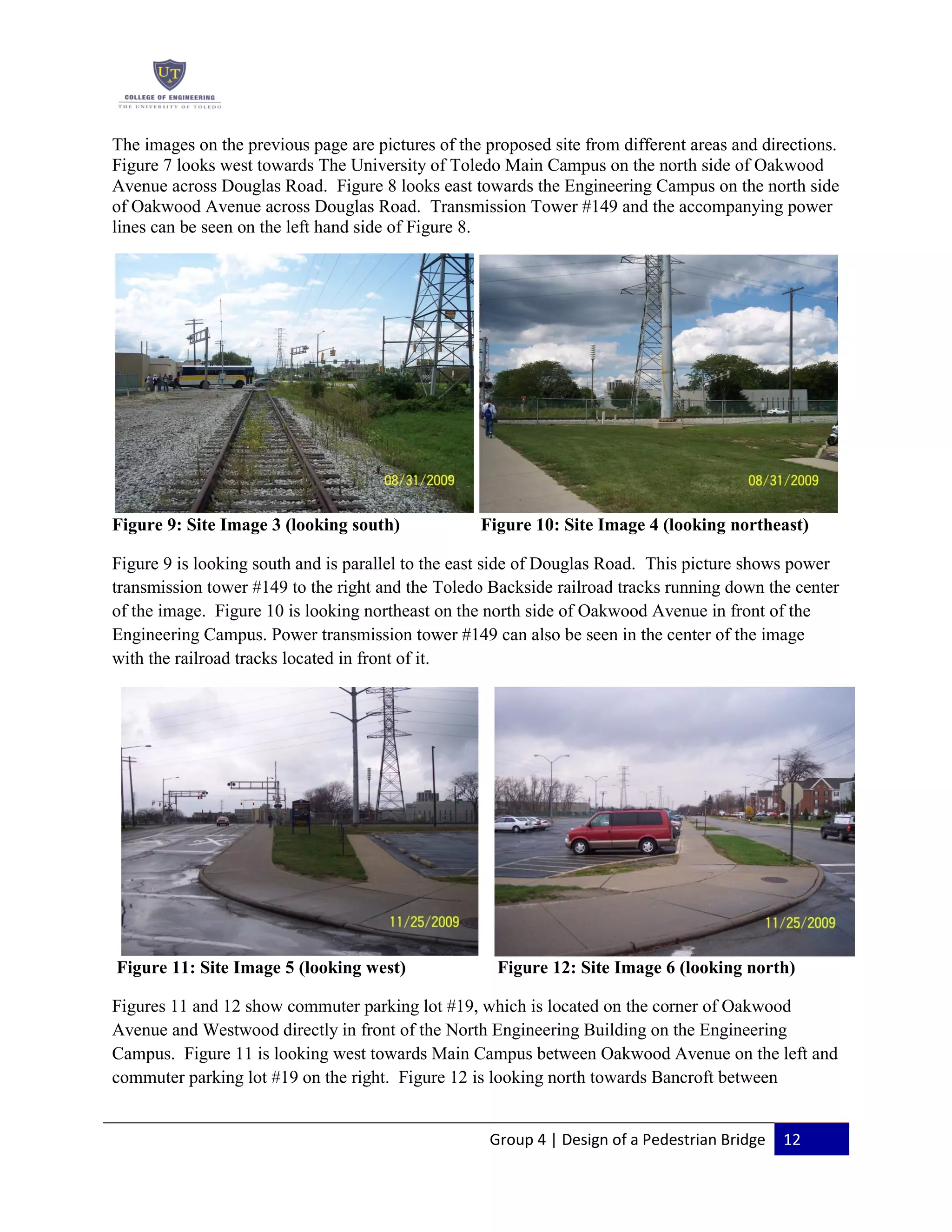
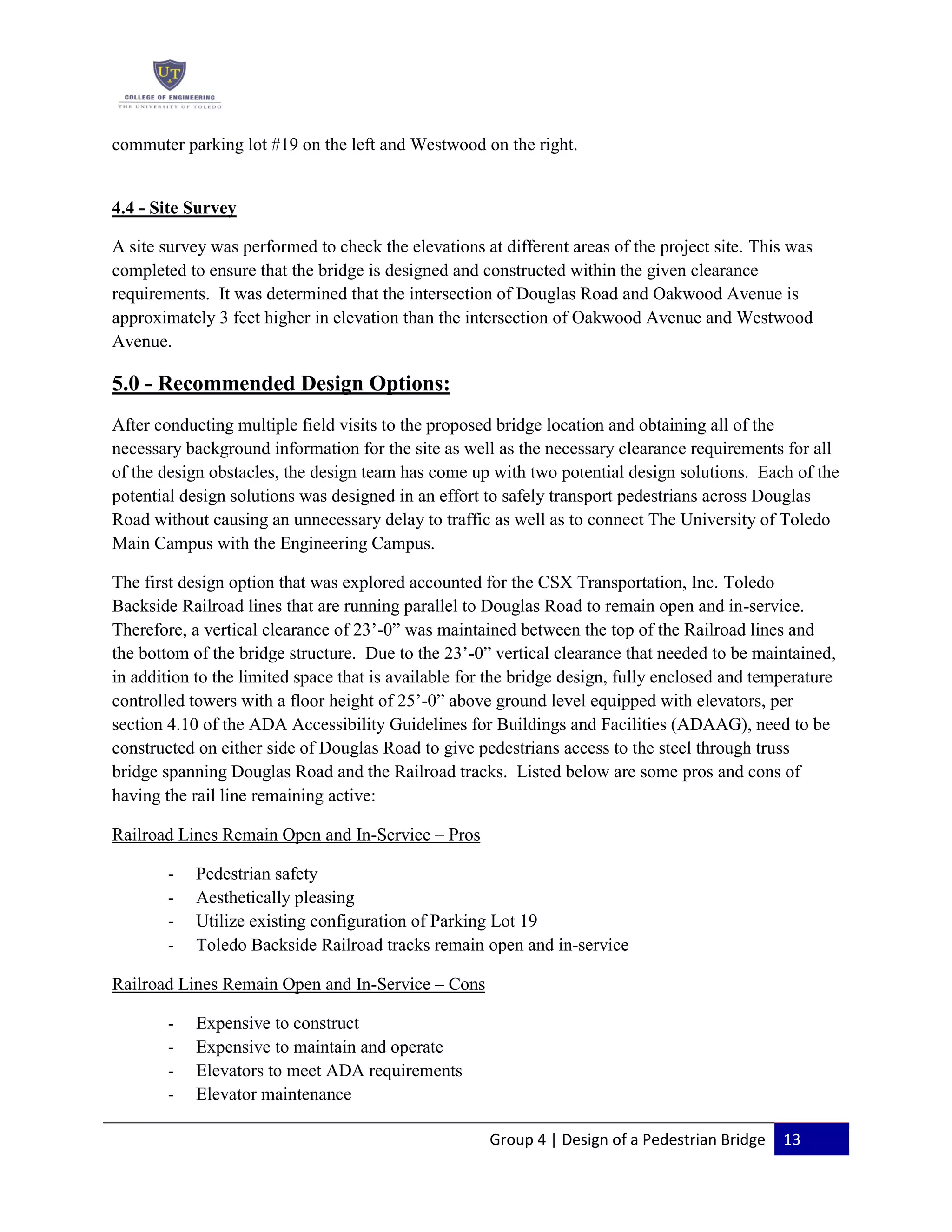
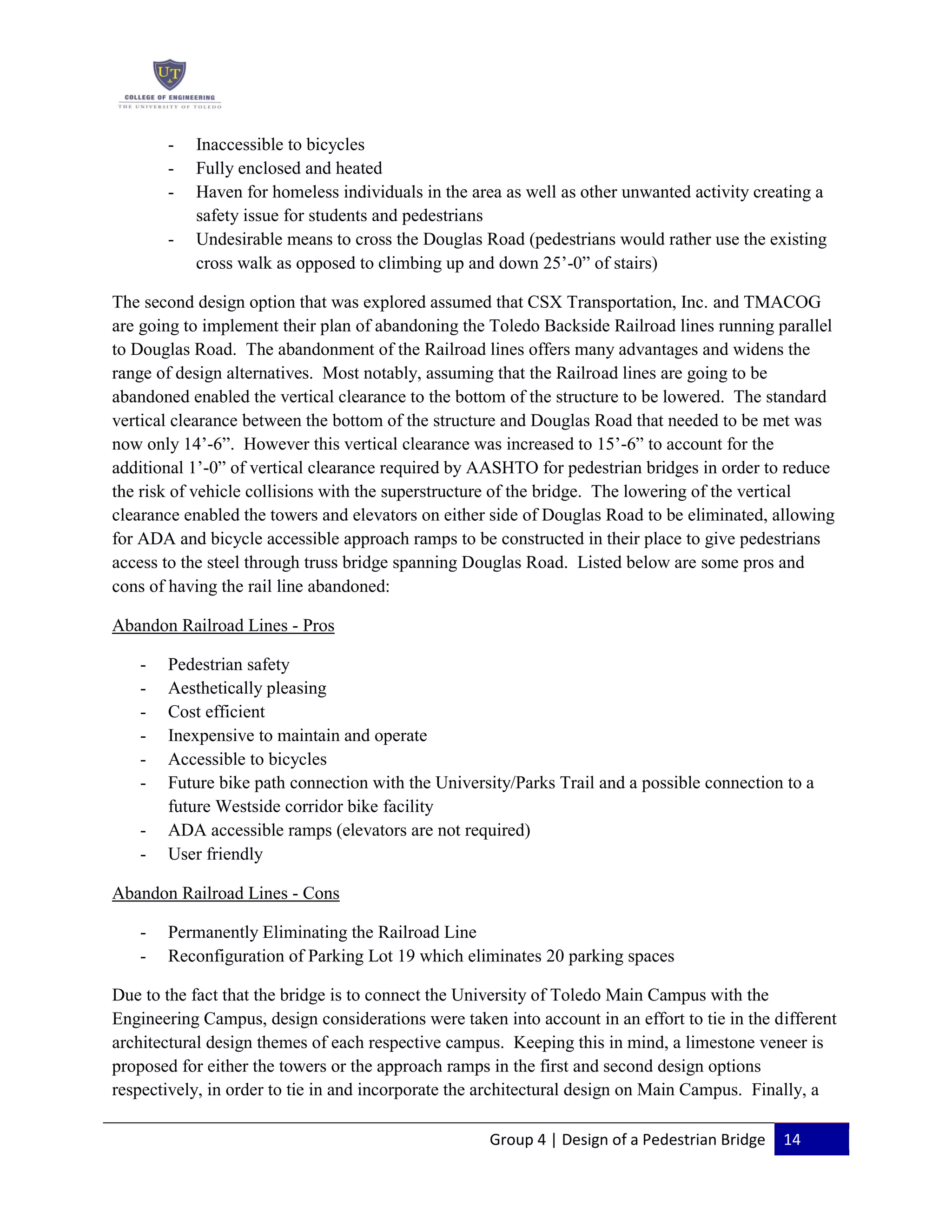
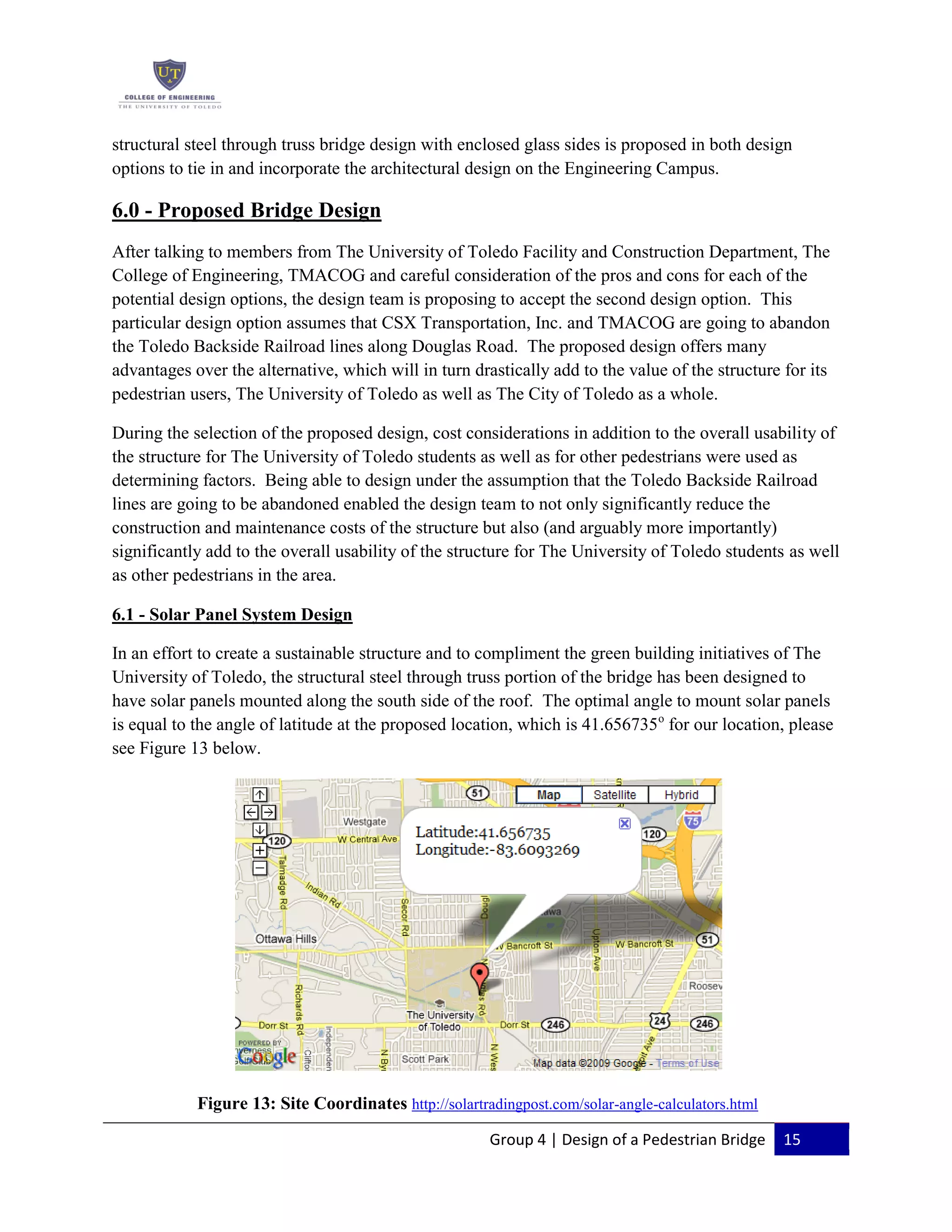

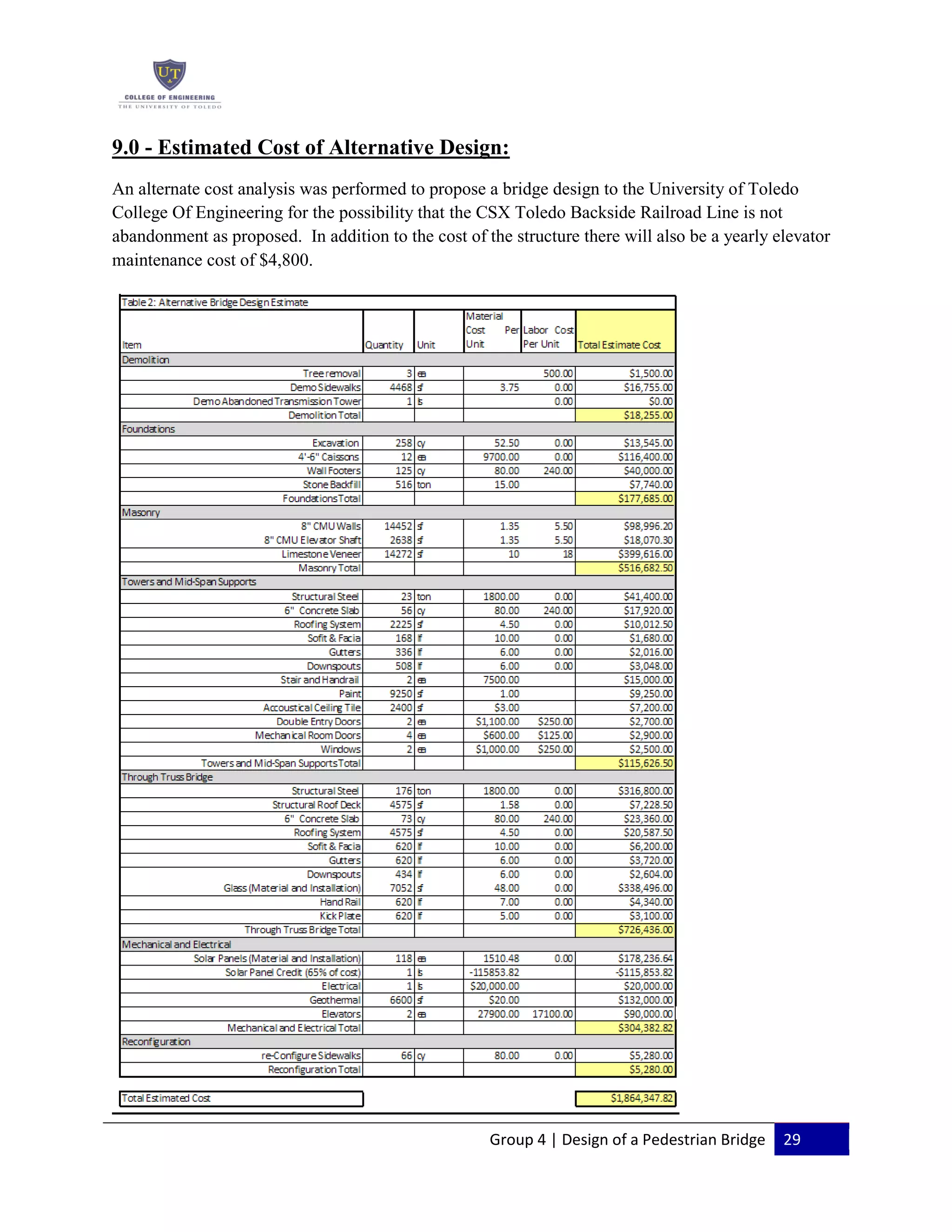

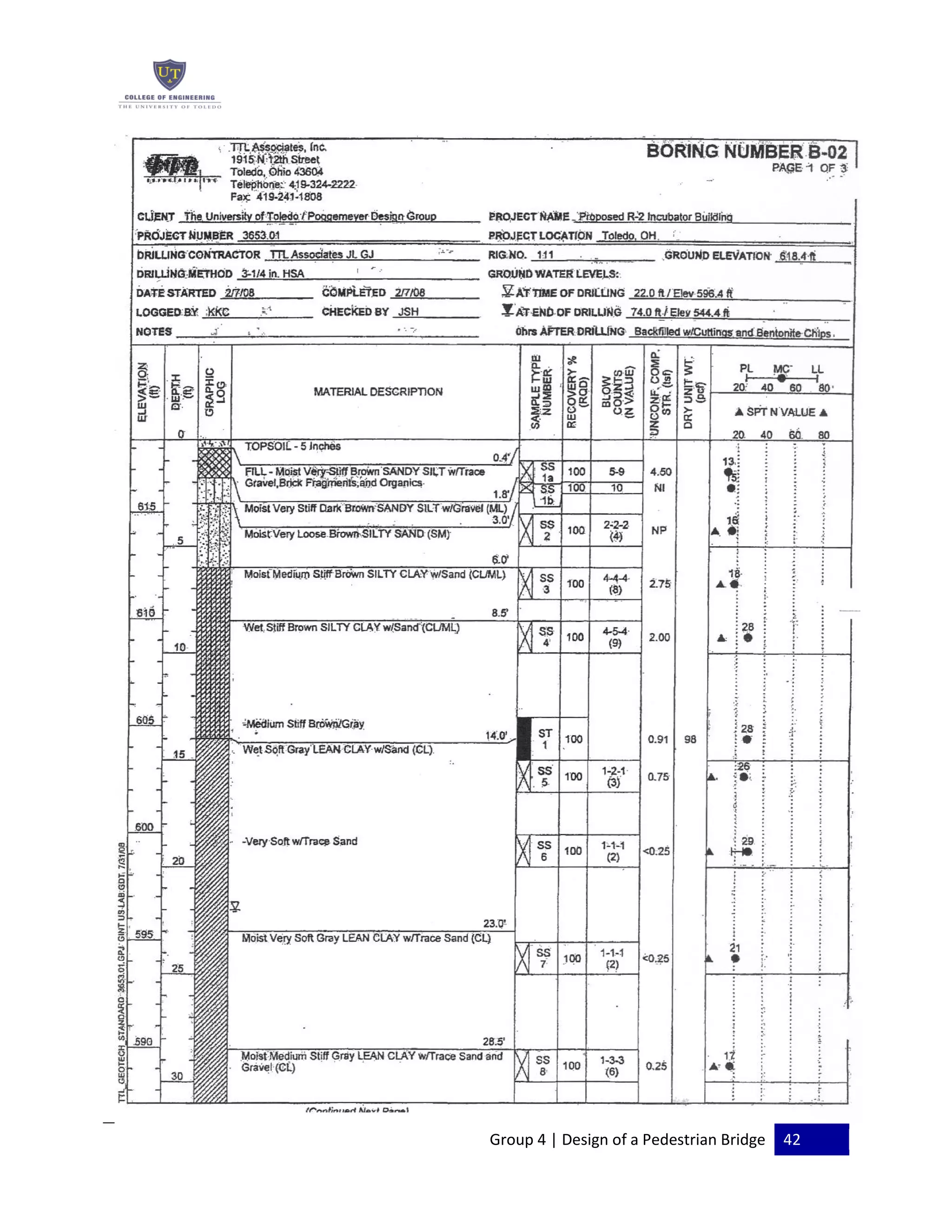

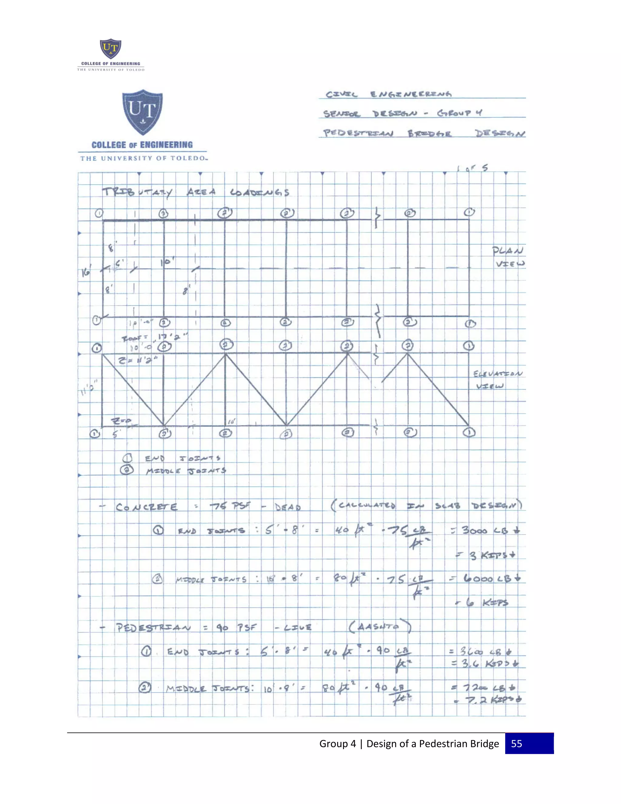
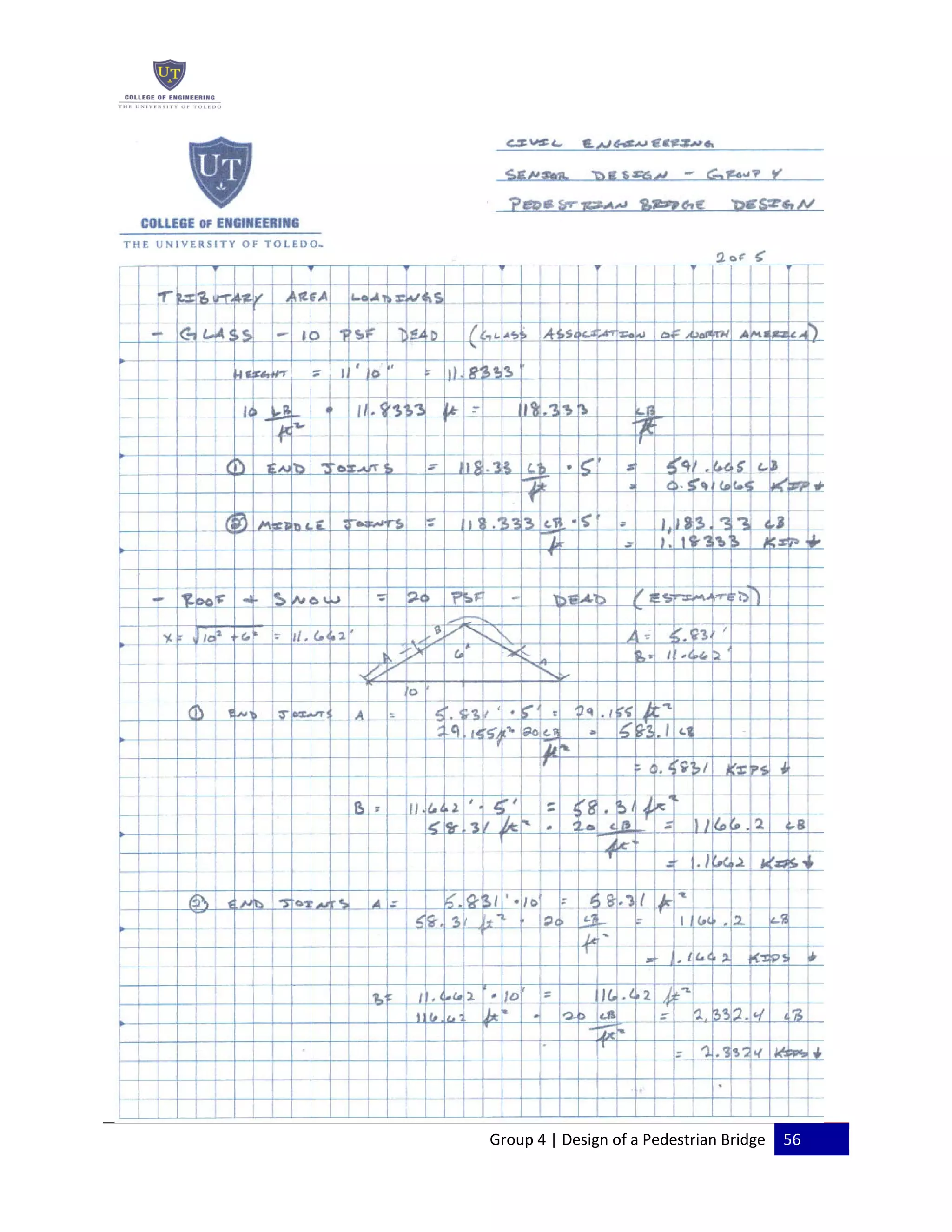
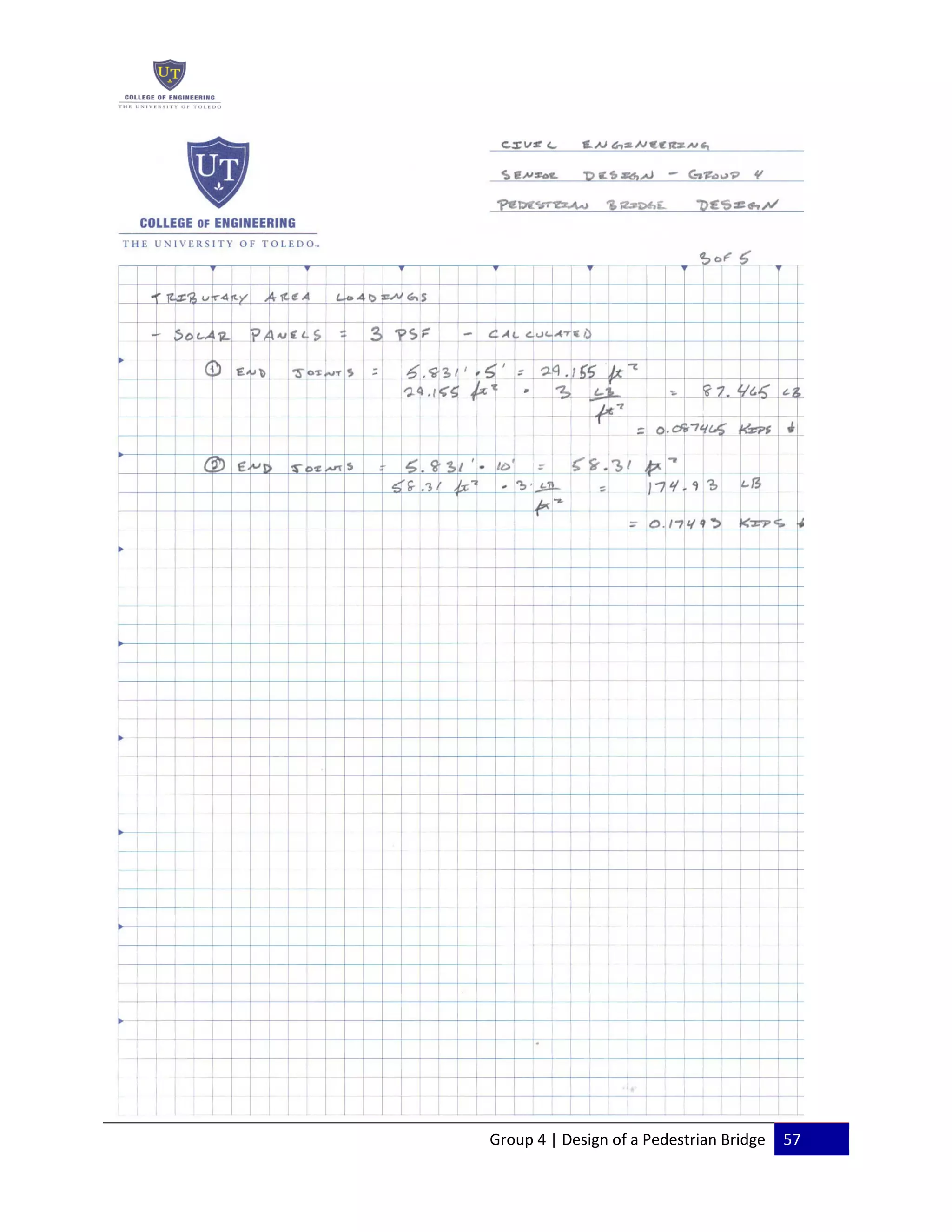
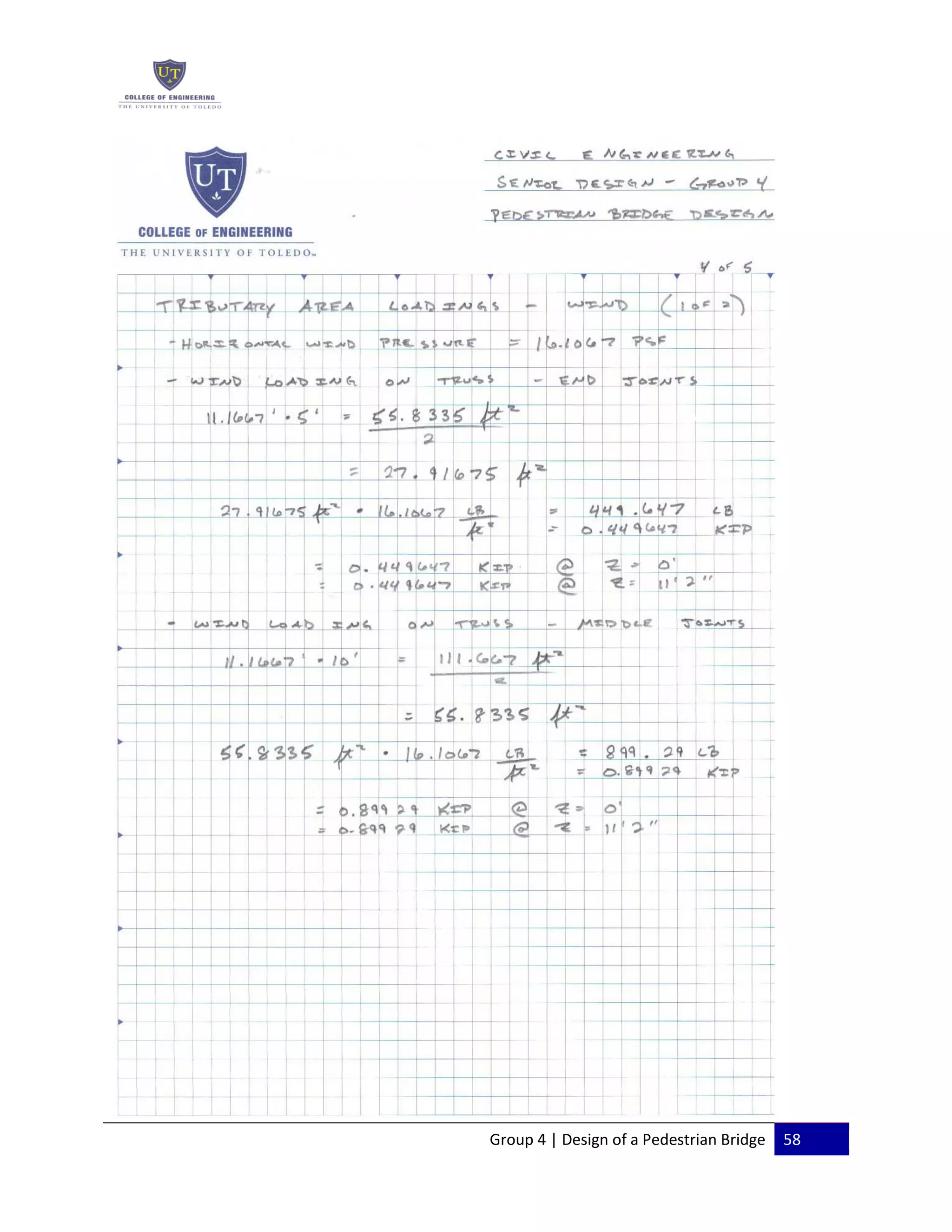


This document is the final report for a senior design project to design a pedestrian bridge between the University of Toledo's main campus and engineering campus. It summarizes the constraints of the project site, which include high voltage power lines, nearby railroad tracks, and poor soil conditions. It then describes site visits where traffic and pedestrian counts were collected. Two potential bridge designs are recommended to safely transport pedestrians across Douglas Road between the campuses.


