Downloaded 575 times


![v
List of Figures
Figure 1- Control Cabinet................................................................................................................6
Figure 2- Motor Operated Valve at the site .....................................................................................7
Figure 3 - Example of weakly progress meeting .............................................................................8
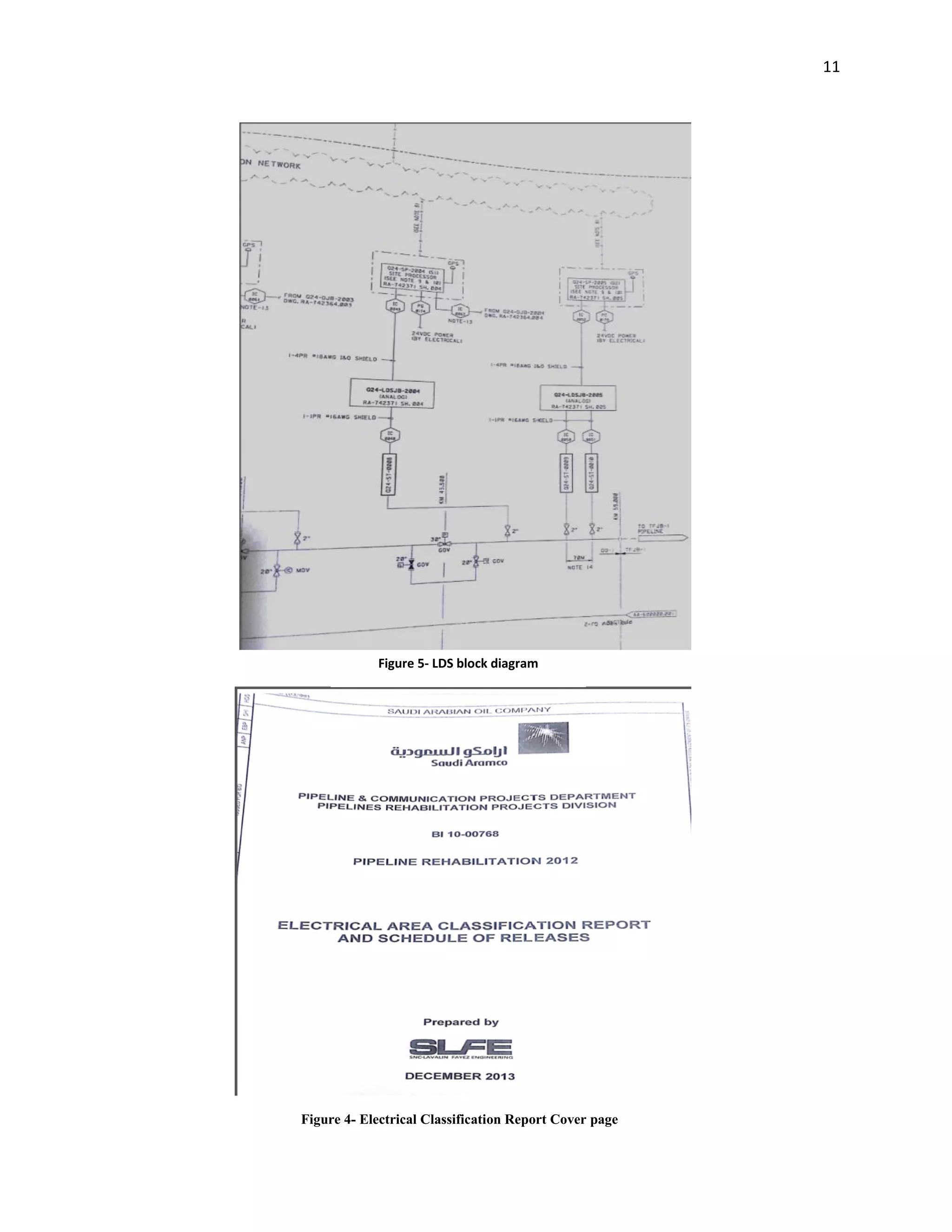
Figure 4- Electrical Classification Report Cover page ..................................................................11
Figure 5- LDS block diagram...........................................................................................................11
Figure 6- Acoustic Pipeline Leak Detection System (block diagram).............................................19
Figure 7 - WIKA E10 E-10 pressure sensor.....................................................................................20
Figure 8 - WIKA E10 E-11 pressure sensor....................................................................................20
Figure 9 - FSP................................................................................................................................21
Figure 10 - WaveAlert field Processor ..........................................................................................23
Figure 11 - Typical Configuration of APLDS [6]..........................................................................24
Figure 12 - PLDS system drawing [8] ...........................................................................................24
Figure 13 - propagated light spectrum...........................................................................................28
Figure 14- DTS basic components.................................................................................................29
Figure 15 - Fiber Optic Cable..........................................................................................................33
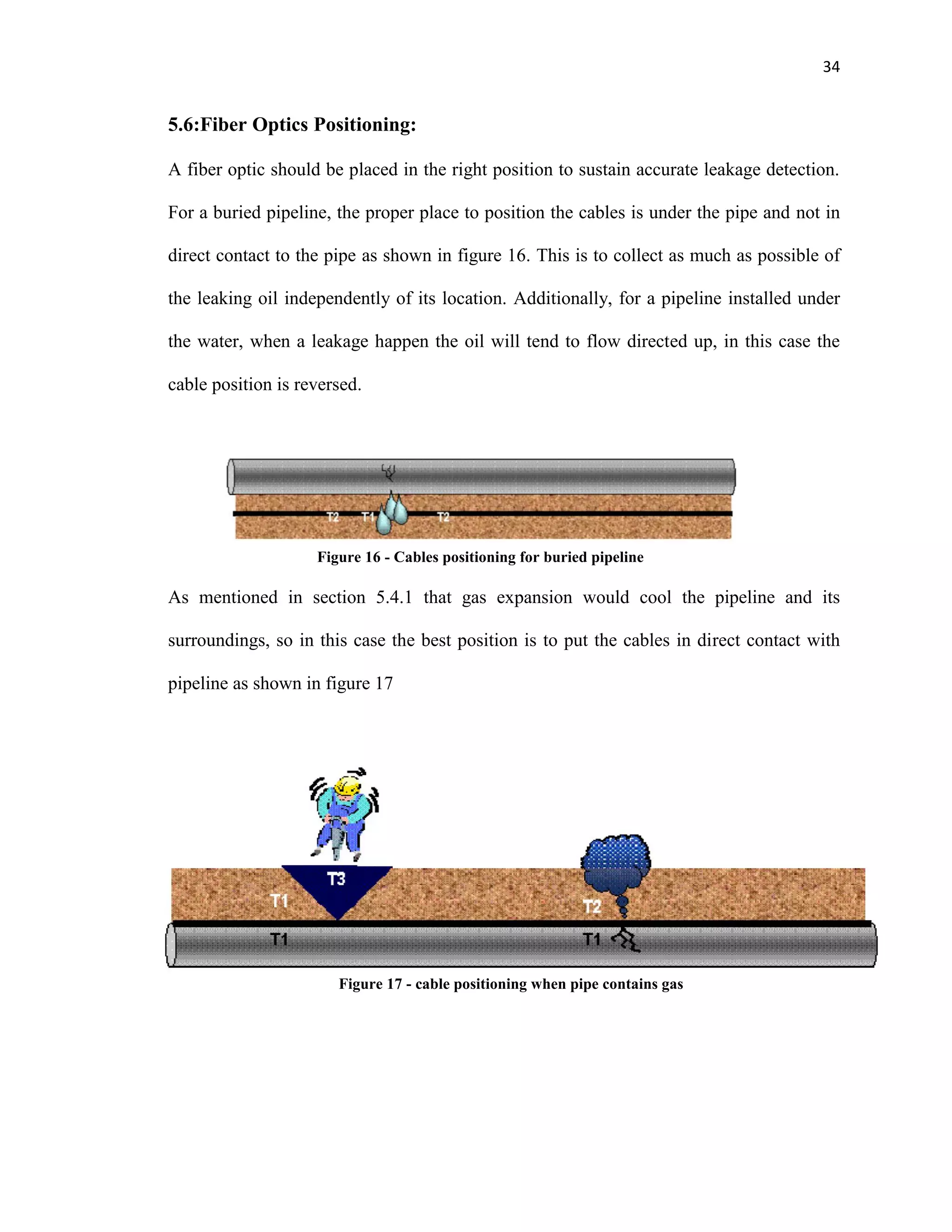
Figure 16 - Cables positioning for buried pipeline ........................................................................34
Figure 17 - cable positioning when pipe contains gas ...................................................................34
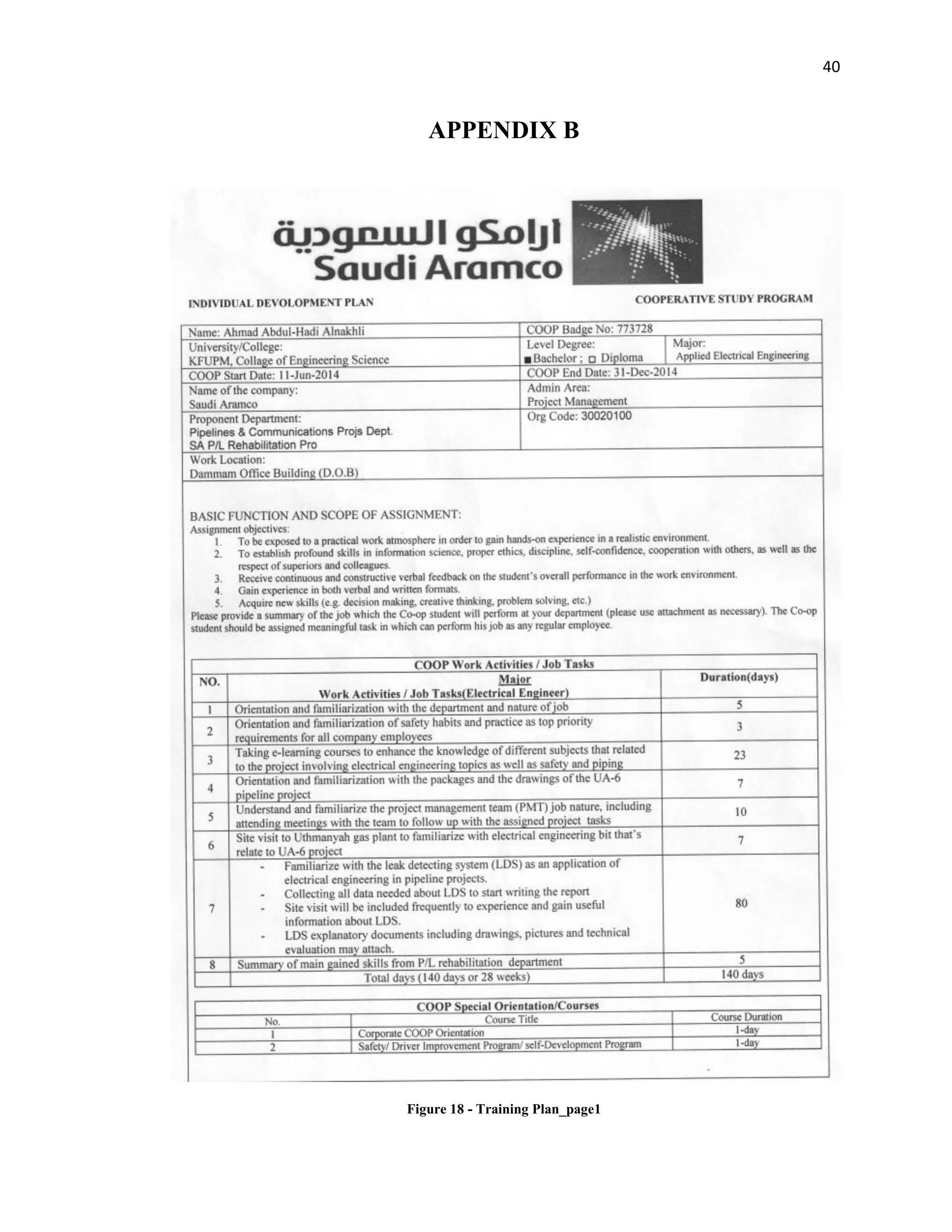
Figure 18 - Training Plan_page1 ...................................................................................................40
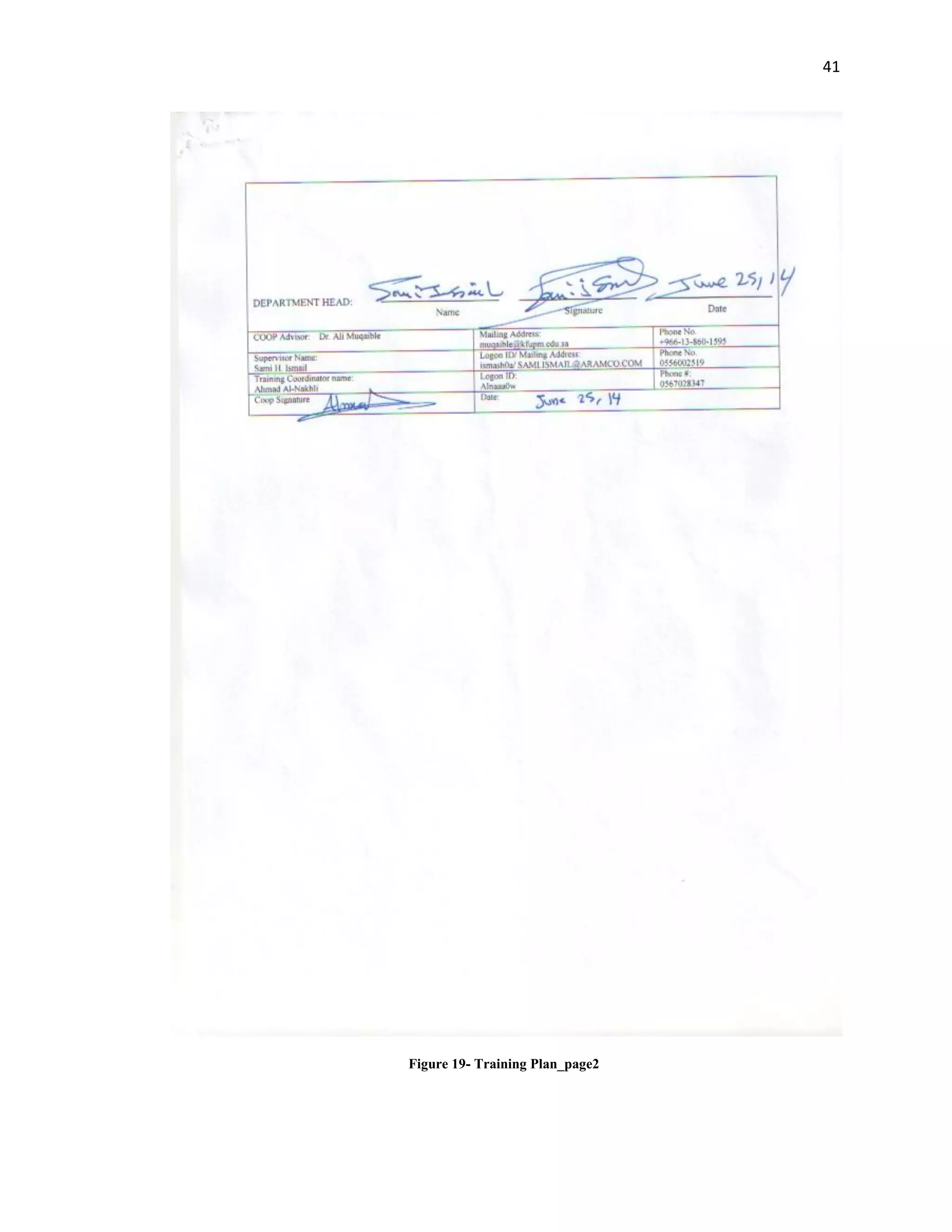
Figure 19- Training Plan_page2 ....................................................................................................41
Figure 20 - Certificate of Training Completion.............................................................................44](https://image.slidesharecdn.com/1e94c670-ea86-41d3-9e48-cd0fc65753be-150826121552-lva1-app6891/75/Final-COOP-Report-6-2048.jpg)
![1
CHAPTER 1: INTRODUCTION:
1.1: Objectives and Motivations
Pipeline networks are the most economic and safest mode of transportation for oil, gases
and other fluid products. As a means of long-distance transport, pipelines have to fulfill
high demands of safety [4]. Short pipeline distances have also a risk to face leaks
conditions. Therefore, Saudi Aramco as an example of oil companies that deal with
multiple types of pipelines to connect different regions all over the kingdom area for
supplying fuel that classified some times as extremely hazardous materials. Therefore
they consider delivering it safely is a competitive challenge. Over the years there was
several ways of controlling the safety of pipes leaks that developed by the company itself
or a contractor party.
Instrumentation engineers have to fulfill and sustain cretin features and characteristics of
each product introduced by whatever party considering all procedures and standard that
have been sit up by Saudi Aramco. Therefore leak detection pipeline leak detection has
an essential role for every pipeline project nowadays.
1.2: Environment contamination and Risks:
Due to the rapid increase in the number of pipeline being designed and constructed, the
demand of finding the safest mode to detect and control leaks in transported hazardous
and toxic products carried in pipelines is highly needed. While Small leaks have the
potential to turn into an expensive and dangerous event if not detected and stopped in
time, risks can also include risk to equipments, personnel safety, environmental
contamination, production losses, cleanup and medical expenses.](https://image.slidesharecdn.com/1e94c670-ea86-41d3-9e48-cd0fc65753be-150826121552-lva1-app6891/75/Final-COOP-Report-8-2048.jpg)


![12
Chapter 3: Introduction to pipeline leak detection system
3.1: PLDS System:
Pipeline Leak Detection System (PLDS) is a system comprising field sensors, means of
communications, field data collection and processing devices capable of detecting and
locating leaks along pipelines networks, managing nuisance without affecting
performance for specified PLDS application and generating leak events and displaying
system status information to pipeline control committee. In the coming sections and
chapters I may use several phrases related to pipeline engineering which you can find its
definitions in Appendix A [1]
PLDS is an integration of hardware and software, including sub-systems and components
parts, which as a whole, is capable of meeting the required performance level. Those
PLDS requirements can be summarized as the following according to Saudi Aramco
Engineering Standards (SAES-Z-003).
Firstly, PLDS have to detect the leaks when they occur, determine the location of the
leak, estimate the magnitude and this system has to be developed with an alert system of
leak events. According to SAES-Z-003 the selection of PLDS technology for onshore
pipelines network should meet the minimum performances list required which are listed
at table 2 through table 5 in Appendix C. Furthermore, a study of risk assessment shall be
done to evaluate the impact of major leak events on the neighboring community and
environments. This study has to consider the minimum amount of product leaked and its
impact on the surrounding areas until total isolation is received. Therefore, it will give
reasonable results for determining the required leak detection system performance listed](https://image.slidesharecdn.com/1e94c670-ea86-41d3-9e48-cd0fc65753be-150826121552-lva1-app6891/75/Final-COOP-Report-19-2048.jpg)
![13
in table 2 to table 5 in Appendix C. The selection of technology will be used in detecting
should be approved by Process and Control System Department (P&CSD) during each
project proposal phase that cover leaking detection system considering communication
infrastructure, monitoring system and field instrumentation. Also, pressure, temperature,
density and flow of the pipeline should be considered beside pipeline configuration and
pipeline fluid type in selecting PLDS technology. For operating certain technology its
operating requirements shall be studied to give the high system performance. In the next
section, operating requirements (performance criteria) will be discussed. [2]
3.1.1: PLDS layers:
A PLDS is built on three layers:
1- Field layer: Field devices, including field instrumentation and data collection
devices or field processing unit. Instrumentation equipments include sensors,
cables, flow meters and pressure transducers which are classified either externally
or internally instruments. They measure parameters of the pipeline such as
pressure, temperature, flow of the fluid and the appearance of hydrocarbons. [4]
2- Communication layer: communication devices and links (i.e. protocols and
interface software). Supervisory Control and Data Acquisition (SCADA) is a
computer based system used in leak detection system for monitoring, processing,
transmitting, communicating and displaying data for the pipeline control
sectors.[4]
3- Central processing and display devices, including associated software & security
requirements.](https://image.slidesharecdn.com/1e94c670-ea86-41d3-9e48-cd0fc65753be-150826121552-lva1-app6891/75/Final-COOP-Report-20-2048.jpg)
![15
Table 2 - sensitivity Requirements for Liquid & Gas
Level Description Operating Pressure range
Low
18 mm (0.75 inch) of leak size within 3 minutes
18 mm (0.75 inch) of leak size within 5 minutes
18 mm (0.75 inch) of leak size within 7 minutes
Greater than 600 psig
300psig-600psig
Below 300 psig
Medium
18 mm (0.75 inch) of leak size within 10 minutes
18 mm (0.75 inch) of leak size within 12 minutes
18 mm (0.75 inch) of leak size within 15 minutes
Greater than 600 psig
300psig-600psig
Below 300 psig
High
18 mm (0.75 inch) of leak size within 1 hour
18 mm (0.75 inch) of leak size within 1.5 hour
18 mm (0.75 inch) of leak size within 2 hour
Greater than 600 psig
300psig-600psig
Below 300 psig
As shown in Table 2, the sensitivity requirements are divided into three levels, High,
Medium and low which they divided into three operating pressure ranges which are
major factor of indicating the technology selection of PLDS [2].
3.2.2: Reliability:
Reliability is term that indicates how much is a system can run continuously without
giving wrong results. It is a measure of a PLDS ability to detect and locate the leaks
events with no false alarms while operating within the envelope devolved by PLDS
designers. Unit of measurement is false alarms per year. Therefore, a system regardless of
the fluid type in the pipeline is considered to have high reliability shall not exceed one
false alarm per year, three false alarms for medium reliability system and five false
alarms per year for low reliable PLDS. [2]
3.2.3: Accuracy:
Estimated leak value measured and its location configuration should be valid and within
acceptable rang of tolerance to be accurate enough for selection PLDS technology. For](https://image.slidesharecdn.com/1e94c670-ea86-41d3-9e48-cd0fc65753be-150826121552-lva1-app6891/75/Final-COOP-Report-22-2048.jpg)
![16
high accurate level the system should not exceed ± 200 meters of its actual location, ±
1000 meters for medium accuracy and ± 2000 meters for low accuracy. [2]
3.2.4: Robustness:
A PLDS should be able to function probably and provide useful information regardless of
conditions changed of the pipelines operation or when data is lost or suspected. If the
accuracy of the system is affected by losing communication link or field sensors meaning
that it reduces the accuracy are called a medium robustness system. Whereas if no
effective accuracy reduction happened to the system is considered to be high robust
system and low robust system if the system have failed to give an accurate results when
losing communication link or field sensors. [2]
3.3: Leak Causes:
a) Excavation:
Most significant leaks that do occur are caused by damage from nearby excavation
equipment, therefore it is critical to check prior to excavation to assure that there are no
buried pipelines in the vicinity.
b) Corrosion:
If a pipeline is not properly maintained, it can begin to corrode slowly due to oxidization
of the pipe wall, particularly at construction joints.
c) Others:
Include accidents, terrorism, and earth movement.](https://image.slidesharecdn.com/1e94c670-ea86-41d3-9e48-cd0fc65753be-150826121552-lva1-app6891/75/Final-COOP-Report-23-2048.jpg)
![17
3.4: PLDS technologies:
Technologies of PLDS are divided into internally based LDS that used instrumentation
equipments are usually exist in the area such as pressure sensor and temperature sensors.
Their cost is slightly moderate than externally based LDS which are usually using high
sensitive and accurate sensors for measuring LDS that quite costly than internally.
Internally based LDS:
- Pressure/Flow monitoring
- Acoustic Pressure Waves
- Balancing methods
- RTTM methods
Externally based LDS:
- Digital Oil Leak Detection Cable
- Infrared radiometric pipeline
testing
- Fiber-optic leak detection
Currently Saudi Armaco is using the acoustic pressure waves system which I going to
discuss in my first case study and it is planning to bring the fiber-optic leak detection
system that I will introduce in my second case study. [1]](https://image.slidesharecdn.com/1e94c670-ea86-41d3-9e48-cd0fc65753be-150826121552-lva1-app6891/75/Final-COOP-Report-24-2048.jpg)
![19
time difference of the detected signals. The system is using high accuracy performance
and they are coincide with Saudi Aramco engineering standards for pipeline leak
detection system (SAES-Z-003) introduced in chapter 3 of the report. The system is used
widely for liquid pipelines content and rarely used in gas pipelines due to fast attenuation
of the pressure wave signal [5].
Acoustic leak detection system is designed to be compatible in any area classifications.
his techniques is the m st accurate, fast and sensitive’s s luti n f leaks event available
in the market today according to Pipeline Technology And Services (Pipe techs) . Field
Signal Processing (FSP) in ALDS is continuously reviving the pressure wave signal from
transducers installed in the pipe and by using filtering and developed processing
techniques this device is responsible for sending and declaring the leak events to the
central monitoring computers or SCADA system described in section 3.1.1 which will
calculate the leak location using time difference methodology after receiving at least two
leaks report from the field sensors. Figure 6 is showing block diagram of a basic APLDS.
[6]
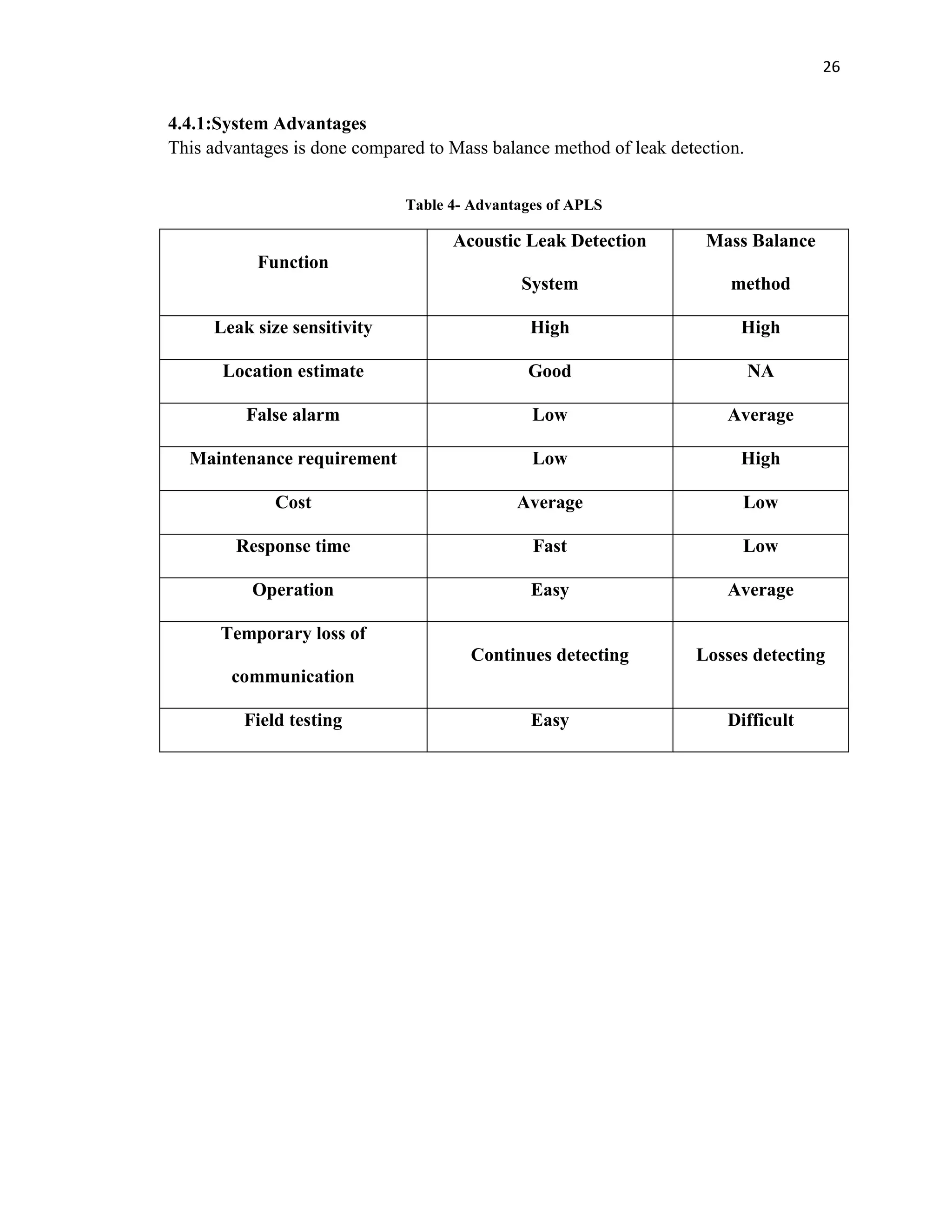
Figure 6- Acoustic Pipeline Leak Detection System (block diagram)](https://image.slidesharecdn.com/1e94c670-ea86-41d3-9e48-cd0fc65753be-150826121552-lva1-app6891/75/Final-COOP-Report-26-2048.jpg)
![20
4.3: System components:
4.3.1: Pressure Sensors:
Different types of pressure sensors with high sensitivity are used for detecting pressure
wave signals where the selection of these sensors are depending on the level of accuracy
and sensitive of the system, the classification area and the specifications of the pipe itself
such as its diameter , length and type of the pipe contents.
The sensor in figure 7 is provided by Pipe Techs company whereas the one in figure 8 is
provided by Acoustic System Incorporated (ASI) company which is the used sensor in
Saudi Aramco pipeline projects. They are responsible for data acquisition and
transmission of the pressure wave signals. Both sensors have the same technical
specification which are compatible with SAES. [6] [7]
Figure 8 - WIKA E10 E-11 pressure sensor Figure 7 - WIKA E10 E-10 pressure sensor](https://image.slidesharecdn.com/1e94c670-ea86-41d3-9e48-cd0fc65753be-150826121552-lva1-app6891/75/Final-COOP-Report-27-2048.jpg)
![21
The following table is listing sensors features.
Table 3 - Pressure Sensors Spicifications
Table 3 shows the pressure sensors specification in pipeline projects for leak detection,
the voltage supplying will be feed up by FSP with the listed value. The span range means
that the two end sensors separation shall not be less than 80 meters. [6]
4.3.2: Field Signal Processing (FSP):
Field Signal Processing is powerful unit that is capable of monitoring real-time signal,
data acquisition and control processing. This component of the system should be
withstanding harsh environment conditions.
Figure 9 shows the FSP provided by the National Instrument Corporation (US-Based
facility). In the field, the FSP should be installed inside a cabinets which placed in field
equipment shelters.
Voltage Supply 10 – 30 V
Output signal Current signal: 4 – 20mA
Connection to FSP Two instrumentation cables
Sampling rate 1000 samples per seconds
Span range greater than 80 meters
Figure 9 - FSP](https://image.slidesharecdn.com/1e94c670-ea86-41d3-9e48-cd0fc65753be-150826121552-lva1-app6891/75/Final-COOP-Report-28-2048.jpg)
![22
FSP operation
The FSP operation includes the following:
a- Data Acquisition
b- Electrical noise filtering
c- Pressure signal filtering
d- Communication
e- Time indicating
During losing of communication network, FSP will register all leaks event sorted in a
memory and then transmitted with a time indicator of each event to the control center as
soon as the network is back. It will read pressure signal at a sampling rate of 1ms after
passing the filtering level of analog and digital signals. Then, the signal will be averaged
to 20 readings per second and used to create a signal profile to compare it with mask
signal (original) to indicate the pressure wave leaks on it. Global Positioning system
(GPS) is used to synchronized al time stamping in the system to get more accurate
results. Moreover, in the absence of leaks events, a profile will be sent continuously to
the control center indicating the state of the pipe. [6]
WaveAlert field processor
WaveAlert field processor is an example of FSP that will be used to convert analog
signals to its digital form using A/D converters, create correlation profile and compare it
with threshold to perform the system test and using GPS for synchronization. This devise
is provided by ASI under the following specifications:
1) Standard input / outputs including 4-20 ma, dry contact relays, optically isolated
inputs
2) Robust, high reliability, industrial temperature design for in oil and gas industry
3) Low maintenance
4) Easy installation
5) Easy replacement](https://image.slidesharecdn.com/1e94c670-ea86-41d3-9e48-cd0fc65753be-150826121552-lva1-app6891/75/Final-COOP-Report-29-2048.jpg)
![23
Figure 10 is showing the WaveAlert field processor installed. [7]
4.3.3: Control Center:
The control center (CC) is responsible for collecting all reports are coming from FSP and
deciding on them whether they are leak events or just indicating pipeline pressure status.
Basically the job of CC is to sort the reported events from FSP and send it to SCADA
where the decision is made on the condition of the pipeline. A typical configuration is
made by Pipe Techs company (figure 11) illustrating a leak events detection and location
structure.[6]
Figure 10 - WaveAlert field Processor](https://image.slidesharecdn.com/1e94c670-ea86-41d3-9e48-cd0fc65753be-150826121552-lva1-app6891/75/Final-COOP-Report-30-2048.jpg)
![24
Figure 11 - Typical Configuration of APLDS [6]
Figure 12 - PLDS system drawing [8]](https://image.slidesharecdn.com/1e94c670-ea86-41d3-9e48-cd0fc65753be-150826121552-lva1-app6891/75/Final-COOP-Report-31-2048.jpg)
![25
4.4: APLDS operation principles:
Acoustic pipeline leak detection system is the most known system used in pipeline
projects nowadays due to its fast and accurate response (1 minute) and its capability of
detecting and locating small as well as large leaks events. When a leak event is occurred
due to pipeline wall cracking a drop of pressure will consequently appear in the pipeline
fluid which result in a traveling pressure wave that will oscillate in opposite directions of
its source at the speed of sound which gave the system its name (Acoustic). Therefore by
placing two pressure sensors (S1 & S2) at each extreme end of certain distance of the
pipeline it will be able to detect this signal that traveled through the pipeline wall and
transmit its response to the associated communication devices (FSP) that will reduce the
noise associated with the signal considering pipeline parameters such as the viscosity of
the fluid, its speed and pressure. Each leak event will be time stamped using GPS
synchronization. Then, it will be sent to CC for further indication to determine whether
the leak is happened or not. [6]
Determining the location of the leak is depending on pressure wave propagation velocity
in the fluid, location method will involve in its calculation the time difference of the
arrival pressure wave (t1-t2) and the pipeline length (L) as shown in the following
equation:
Where:
Xv = Distance from the leak source to segment end of the sensor
L = Pipeline length
t1 = detection time at sensor 1
t2 = detection time at sensor 2](https://image.slidesharecdn.com/1e94c670-ea86-41d3-9e48-cd0fc65753be-150826121552-lva1-app6891/75/Final-COOP-Report-32-2048.jpg)
![28
5.2: Distributed Temperature Sensing:
It is an optoelectronic system measure temperature by means of optical fibers working as
linear sensors. Rather than detecting at a single point, temperature is measured through a
fiber optical cable which will lead to a higher accuracy of detecting over long distance
pipelines. The temperature will affect the fiber glass changing the light transmission
characteristic in the fibers. As a result of that, the external physical parameters
(temperature) that changing the fibers characteristics can be localized which means that
fiber optics is going to be working as linear sensors. [8]
Fiber optic cable is made of doped quartz glass that affected by thermal excitation leading
to an interaction between this excitation and the electrons of molecule of the solid called
light scattering. A backscattered light particles will have the information of the local
temperature when the scattering is happened. Thus, it will have two components which is
the Stoke and the Anti-Stoke components. However, not all of the components is used for
detecting because the Stoke amplitude component is temperature independent. To remove
the Stoke component the Raman sensing technique is used to filter the backscattered
frequencies and to only have the temperature dependent component (Anti-Stoke
component) that will help in detecting and locating the leak. Figure 13 a scattered light
spectrum fr m a single wavelength λ0 propagated in fiber optic cable. [8]
Figure 13 - propagated light spectrum](https://image.slidesharecdn.com/1e94c670-ea86-41d3-9e48-cd0fc65753be-150826121552-lva1-app6891/75/Final-COOP-Report-35-2048.jpg)
![29
5.3: DTS components:
components of temperature measurement system include a controller that consist of a
high frequency mixer, laser source, optical module, micro-processor unit and a receiver.
Moreover, line-shaped fiber optic cable made out from quartz glass to function as
temperature sensors. Noticing that the system has a few components that can be
implemented over a large area as shown in figure 14, the system has an advantage over
other detecting system. Fiber optics system has no moving parts which is considered to
be easier in operation and maintenance. Moreover, as it is linear-shaped cables it is more
convenient to use it for long distance pipelines. Also these cables have high immunity to
electromagnetic waves distortion which will decrease interfering signals with background
noise dramatically. It is a passive system have no active electronics component along the
cables, used in hazardous areas safely and have high reliability over long terms. [8]
Figure 14- DTS basic components](https://image.slidesharecdn.com/1e94c670-ea86-41d3-9e48-cd0fc65753be-150826121552-lva1-app6891/75/Final-COOP-Report-36-2048.jpg)
![31
5.4: Principle of operation:
Fiber optics sables should be positioned along the pipeline length and a source of light
such as laser beams or Light Emitting diodes (LEDs) is injected through the cables. The
lighting beam will be scattered in the fibers and Raman Stoke and Anti-Stoke
components will be appeared and measured when it returns to the emitting source
originally. Raman technique of measurement depend on the intensity of the light which is
related to the temperature of the optical medium. The relationship of measuring the
temperature in optical fiber is given in the following equation. [10]
Where :
vo : Wave number of incident light
vk: Wave number shift of material
h: lanck’s c nstant
k: Boltzmann's constant
c : speed of light in optical fiber
T absolute temperature
Ia : intensity of anti-Stokes light
Is intensity of Stokes light
Measuring the intensity of Raman scattered wave will lead the fiber optic sensor to
measure the temperature in the portion where the light scattered. Therefore, this
technique is used for detecting leaks in pipeline by measuring the temperature changed
due to the leak. [10]](https://image.slidesharecdn.com/1e94c670-ea86-41d3-9e48-cd0fc65753be-150826121552-lva1-app6891/75/Final-COOP-Report-38-2048.jpg)
![32
Temperature will be sensed by optical fibers not only in a certain point but in continues
line working as linear sensors which will reflect the pipeline profile. As long as the
distance of the pipe is increased a high accuracy of sensing will be reached.
5.4.1: Leakage detection:
Leakage detection using fiber optic distributed temperature mentoring can either detect
local warming in the pipe or cooling in I depending in the type of product transported in
the pipeline. For example:
Gas expansion lead to cooling temperature variation.
Liquid content ( crude oil ) or heating system will lead to warming variation
In both cases the fiber optic system will sense the action and that change will be affected
the general profile of the pipeline. Furthermore, due to the geometry of the fiber optic and
its low propagation loss characteristic monitoring pipe leakage will be excellent for a
long distance. [9]
Localizing Temperature Change:
To localize temperature changing two factors of measurement can be considered. The
first is the space or few meters around the leak event. Secondly, time of the leak event is
included to localize a certain leak event. [9]](https://image.slidesharecdn.com/1e94c670-ea86-41d3-9e48-cd0fc65753be-150826121552-lva1-app6891/75/Final-COOP-Report-39-2048.jpg)
![33
Environment temperature and actual leak temperature:
Problem Description:
how does fiber optic systems discriminate between actual leakage temperature and
environmental temperature varying?
Solution:
fiber optic system should work relative to the no leak status. For example, the system
will measure the temperature profile in the no leak event and over the time if there is a
notable change in the envelope of the profile with certain increase in the temperature,
then it is leakage status.
5.5:Fiber optic features:
Over 30 years the fiber optic specification has increased to meet company clients
requirements and to be used in many telecommunication application. That specification
and features of fiber optic sensors: [9]
a) Immunity to temperature varying: fiber optic can operate over wide temperatures
range (-50o
to 80o
) and can work in pressure exceeding 75 MPa.
b) Long-term stability: fiber optics are designed to be insensitive to humidity and
corrosion
c) Fiber optics now designed to be immune to electromagnetic perturbation to avoid
interaction with the detected leakage.
d) Fiber optic installation has low-cost compared to installing huge amount of
sensors.
Figure 15 - Fiber Optic Cable](https://image.slidesharecdn.com/1e94c670-ea86-41d3-9e48-cd0fc65753be-150826121552-lva1-app6891/75/Final-COOP-Report-40-2048.jpg)


![37
References
[1] Saudi Aramco. Engineering Procedure (SAEP-747). Pipeline leak detection
system.4 March 2014
[2] Saudi Aramco. Engineering Standards (SAES-Z-003). Pipeline leak detection
system. 28 August 2013
[3] Maurino De Febbo, R&D Manager, Asel-Tech Inc., Houston, TX, USA. A new
generation of leak-detection systems for pipelines. March 2013. Retrieved from
Pipelines International
[4] Technical Review of Leak Detection Technologies. Volume I. Crude oil
transmission pipelines. Retrieved from Alaska Department of Environmental
Conservation
[5] Prof. Dr.-Ing. Gerhard Geiger. Principle of leak detection. Retrieved from
KROHNE Oil & Gas
[6] Pipeline Technologies & Services. Company products. Retrieved from
http://www.pipetechs.com
[7] Acoustic System Incorporated. Detect pipeline leaks at the speed of sound.
Retrieved from http://www.wavealert.com/
[8] Ashim Mishra, Ashwani Soni. (2011). Leakage Detection using Fiber Optics
Distributed Temperature Sensing
[9] O.lida, D.Onoda, S.Kono. Expansion of Measuring Range for a Fiber-optic
Distributed Temperature Sensors Applications to Commercial Plants.](https://image.slidesharecdn.com/1e94c670-ea86-41d3-9e48-cd0fc65753be-150826121552-lva1-app6891/75/Final-COOP-Report-44-2048.jpg)


The document describes the training activities and assignments completed by Ahmad Abdulhadi Alnakhli during his 6-month cooperative training program with Saudi Aramco, including working with the project management team on pipeline projects, site visits, meetings, online courses, and reviewing design drawings and reports to familiarize himself with pipeline leak detection systems. It then provides two case studies, the first on an acoustic pressure wave leak detection system and the second on a fiber optic temperature sensing system.