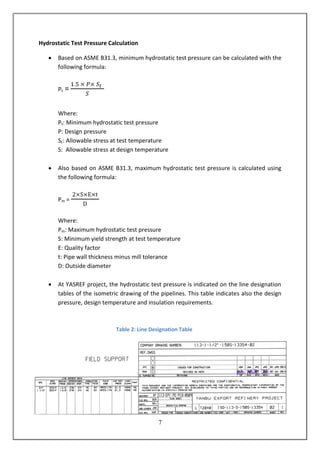
The report describes the knowledge and experience gained during a 28-week internship at YASREF, a refining company under construction. It focuses on several construction activities observed, including pressure testing of pipes, post-weld heat treatment of welding joints, tightening flange bolts, pump alignment, and belt splicing. Each activity is described in detail with photos and references to standards. The report also includes three case studies, the first being a designed base case and the others involving problems encountered during construction.
![34
References
1. YASREF Overview. (n.d.). Retrieved from http://www.yasref.com/about/overview
2. Project Overview. (n.d.). Retrieved from http://www.yasref.com/project/overview
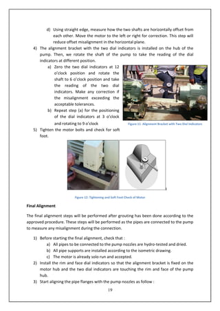
3. Splicing and repair manual. Retrieved from http:// www.blairrubber.com /pdf/Blair_
Splicing Manual.pdf
4. Mullan, H. Heat tracing basics. [PowerPoint slides]. Retrieved from http:// www.
Mullanconsultants.com/pdf/heat_tracing/Heat%20Tracing%20Basics_SLIDES-HRM-
300410.ppt
5. PENTAIR. (n.d.). Skin-effect heat-tracing system (STS) [Brochure]. Retrieved from
http://www.pentairthermal.com/Images/GB-RaychemSTSskineffectTracing System
APAC-SB-H57124_tcm432-37908.pdf
6. TEMPCO. (n.d.). Heat trace cable [Brochure]. Retrieved from http://www.tempco.
com/Tempco/Section6.pdf
7. Towsley, G. (n.d.). Alignment. Retrieved from http://www.grundfos. com/ content /
dam/CBS/global/whitepapers/Whitepaper%20-%20Alignment.pdf
8. The four easy steps to good shaft alignment. Retrieved from
http://www.carlylecompressor.com/Files/Carlyle_Compressor/Local/US-en/
documents/039-185_5FHShaftAlignment_lowres.pdf
9. YASREF. (2013, October 22). Sulfur pelletizer and loading operation and maintenance
manual. Yanbu, Saudi Arabia: Author.
10. Power Piping,ASME Code for Pressure Piping, B31. (2007). New York: The American
Society of Mechanical Engineers.](https://image.slidesharecdn.com/coopreportfinal-141220073605-conversion-gate01/85/COOP-REPORT-36-320.jpg)


