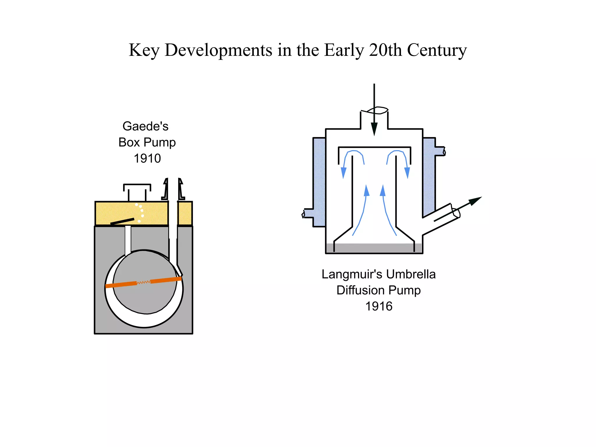
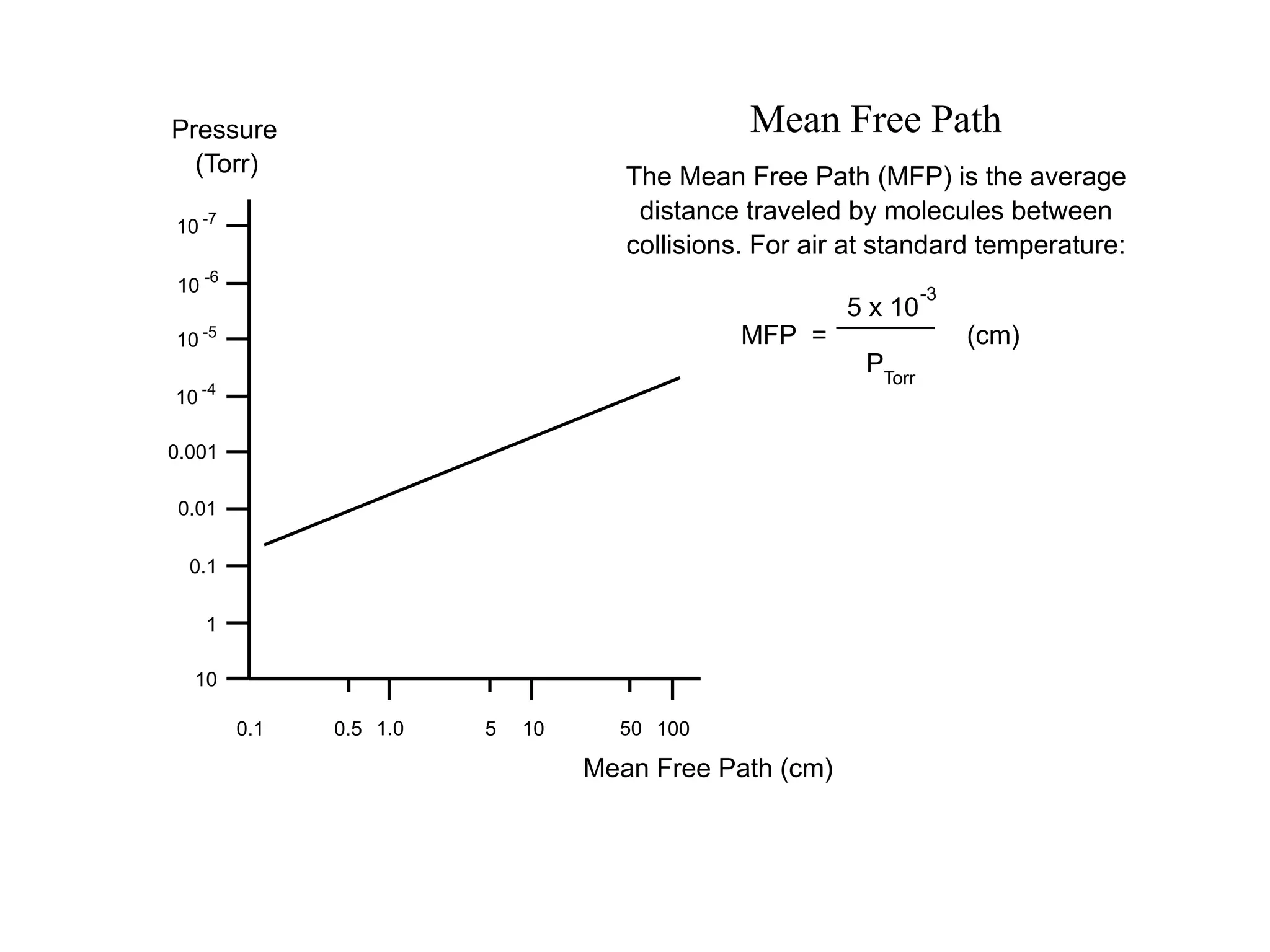
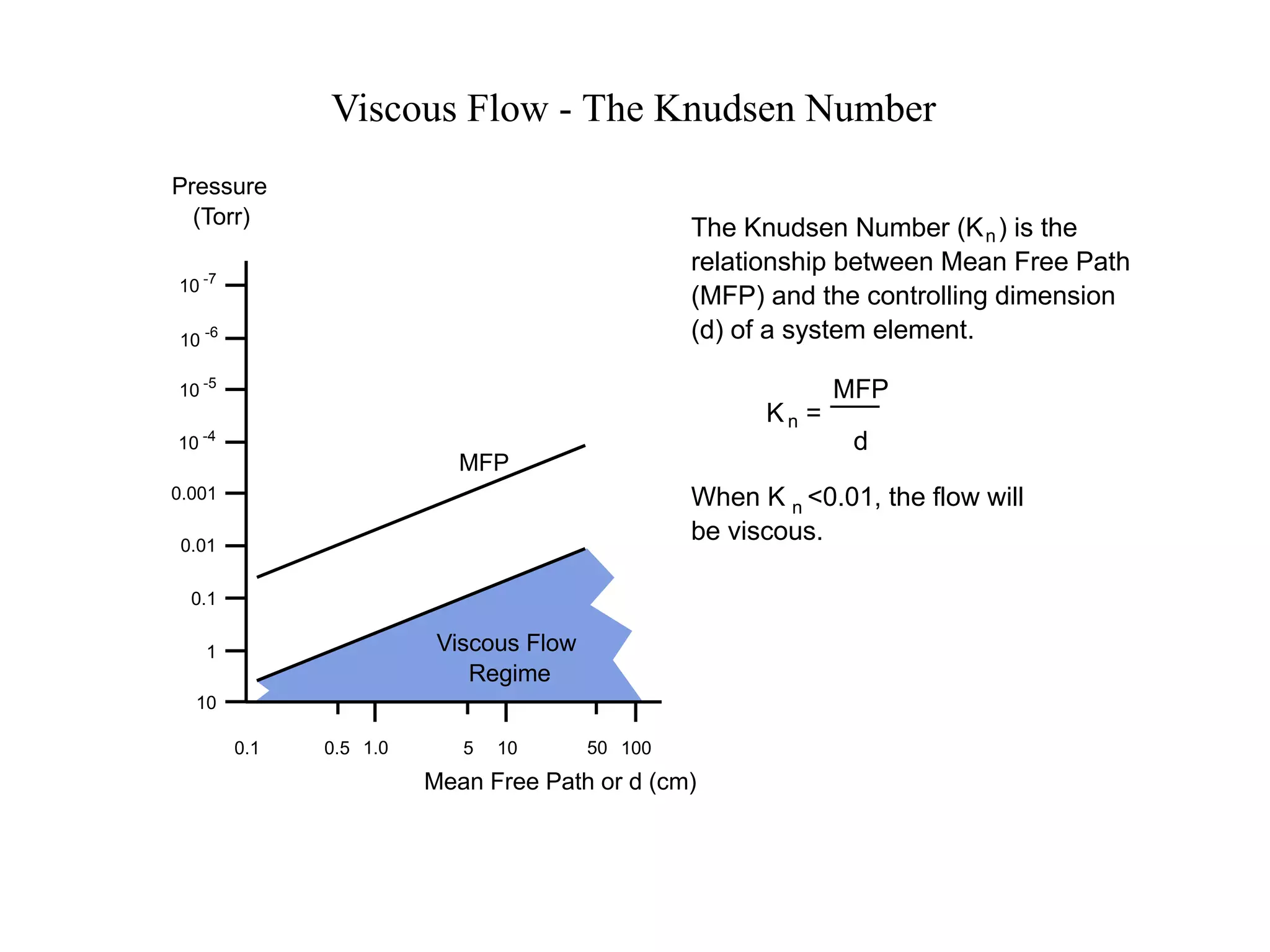
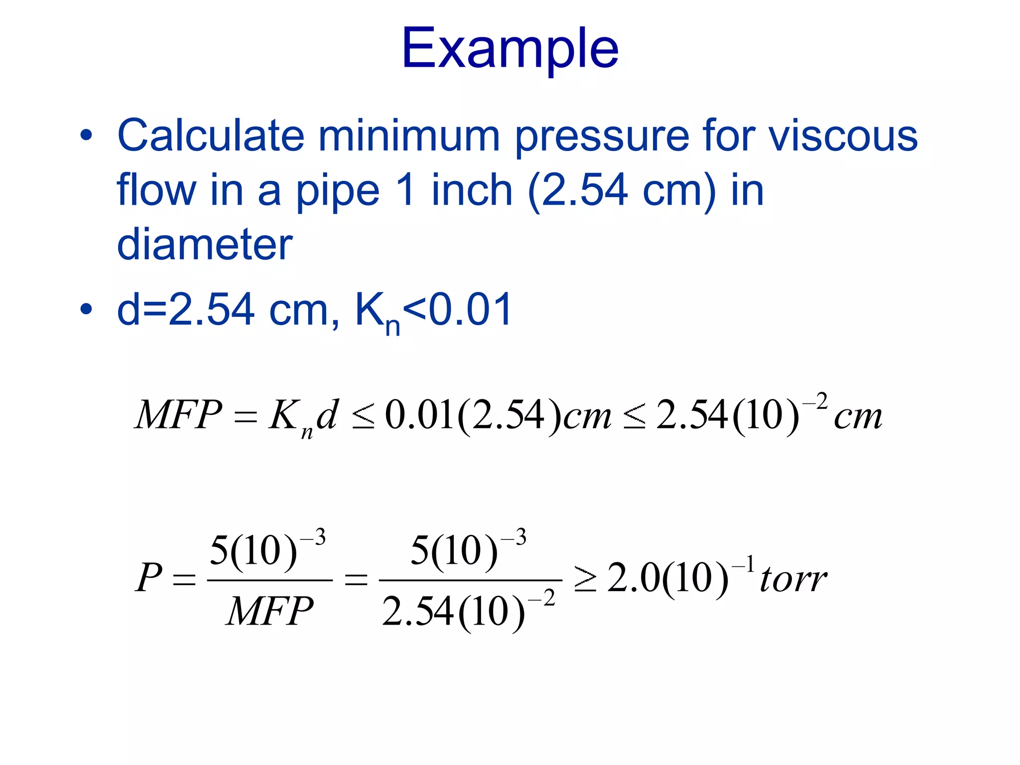
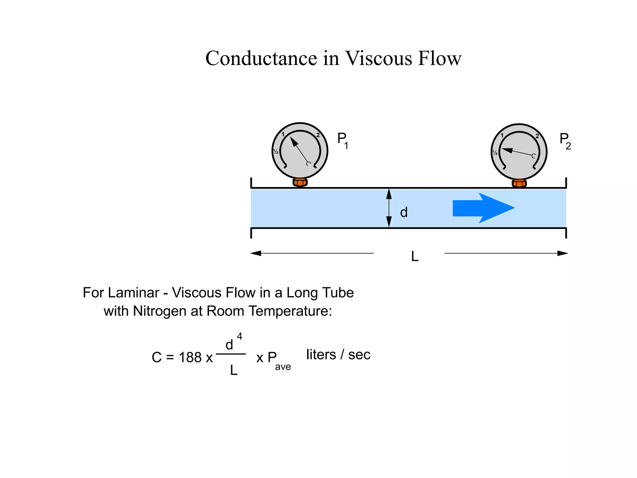
VACUUM AND THIN FILM
TECHNOLOGY
ELET 250
Dr. Fred Strnisa
f.strnisa@hvcc.edu
CLASS ACTIVITIES
• Lectures
• Demonstrations
• Homework
• Laboratory exercises and reports
• Quizzes and exams
• Visit a local clean room facility
GRADES
Weekly quizzes, exams, homework 50%
Lab 25%
Final Exam 25%
Late assignments (lab reports
and homework)
• Late assignments will not be accepted
without a written medical excuse.
• 0ne letter grade will be deducted for
each day an assignment is late.
• All assignments must be turned in at the
beginning of the class for which they are
due.
• Your lowest lab grade and assignment
grade will be dropped.
TEXT (required)
• Hata, David, Introduction to Vacuum
Technology, Pearson Prentice Hall,
2008
• Recommended:
– Vacuum Technology and Coating
www.vactechmag.com
COURSE OBJECTIVES
Study vacuum and plasma generation
techniques used in microelectronic, thin film
and nanotechnology applications
MAJOR TOPICS
• Gas flow
• Pressure regimes
• Gas laws
• Out gassing
• Vacuum production
• Leak & contamination detection
• Residual gas analysis (RGA) techniques
• Thin film deposition technologies
• Safety concerns involved in the
installation, maintenance and operation of
vacuum and thin film equipment.
Why Vacuum ?
Vacuum is critical to most semiconductor fabrication
processes
Understand the hardware
Understand how it works as a system
If you don’t know how it works you can’t use it
intelligently
In many real cases, what you do with or to a vacuum
systems has just as much effect on performance as
the hardware
What is Vacuum ?
Any gas at sub-atmospheric pressure
Vacuum is really the absence of gas
Vacuum is not absolute, but a continuous range of
conditions covering 15 orders of magnitude in
common usage (103 to 10-12 Torr)
Vacuum technology involves moving and removing
gases
How / Why do we use Vacuum ?
• Produce a cleaner environment
– Remove contaminants that can cause unwanted
reactions
• Increase mean free path (MFP)
– Allow sputtering, evaporation and ion implantation
• Control number of surface collisions
– Sputtering of metal layers
– Control rate of film growth in chemical vapor
deposition
• Lower molecular density
– Reduce unwanted contaminants
– Allow plasma
– Increase evaporation rate without increasing
temperature (freeze drying)
– Reduce heat conduction
How / Why do we use Vacuum ?
(continued)
• Create a force
– Hold wafers in place
– Move solids or liquids through pipes
• Reduce heat flow
– Reduced pressure reduces collisions between
molecules and hence heat transfer decreases
– Different gasses have different thermal
conductivities
• Increase vaporization
– Fewer molecules impacting surface or knocking
vaporized molecules back to surface
• Protect materials from reactive molecules
– Pump out reactive molecules and backfill with inert
gas
Clean Environment - Less Matter
Lower Molecular Interference
Low Friction
Thermal Insulation
Promote Evaporation
Unique Electrical Properties
"Suction"
Application
of Force
To Vacuum PumpBeneficial Properties
of Vacuum
Silicon Wafer with Integrated Circuits
Wafer with Scale
How Small ?
Human Hair (cross section) 100 microns
Lower Limit of visibility (naked eye) 40 microns
Smog, Tobacco Smoke 10 microns
Bacteria 2 microns
Virus 0.5 microns
1 micron = 0.001 mm
Devices <0.5 microns
Eight Basic Steps to
Form Semiconductor Device
1. Start with Bare Silicon wafer
2. Oxidize wafer (form SiO2 Layer)
3. Apply photo resist
4. Expose resist through a mask
5. Develop and remove resist
6. Remove exposed SiO2
7. Dope wafer to form pn junction
8. Metallization to form electrical contacts
Eight Basic Steps to
Form Semiconductor Device
1. Start with Bare Silicon wafer
2. Oxidize wafer (form SiO2 Layer)
3. Apply photo resist
4. Expose resist through a mask
5. Develop and remove resist
6. Remove exposed SiO2
7. Dope wafer to form pn junction
8. Metallization to form electrical contacts
3-D Integration
COMPLEX PROCESS
10 -15 processes per layer
>60 layers per wafer
>900 processes per wafer
COSTLY
Facility: $1-10 Billion
Process time per wafer: weeks
High Yield is Necessary
VACUUM IS A CRITICAL PART OF
THE PROCESS
Semiconductor Applications
• Crystal growth
• Oxidation
• Etching
• Doping
– Diffusion
– Ion Implantation
– Epitaxy
• Film deposition
– Evaporation
– Sputtering
– Chemical Vapor Deposition
VACUUM
How to Characterize Vacuum
• Just like we characterize a gas
• Pressure: ( force/area)
– Force exerted is not really a useful concept
• Volume:
– Volume of container
• Temperature:
– Temperature of the walls (almost always)
• Number Density: ( number of molecules per unit
volume )
– Related to Pressure
– A more useful quantity than actual “pressure”
Units of Pressure
Pressure is Force per
Unit Area
• Pounds/sq. in
• Newtons / sq.meter
• Tons/ sq. angstrom
Atmospheric Pressure
• 14.7 pounds/sq. in.
• 105 Newtons/sq.
meter
• 760 Torr
• about 1 ton/sq ft
SI UNITS:
• Pascal = 1 Newton/
sq. meter
• 1 atm = 105 pascals
Non-Si Units: (common
units)
• Torr, milliTorr
• Bar, millibar
Torr is widely used and
understood
• Avoiding it is difficult
“Common” Pressure Units
Pascal, Torr, Bar
Basic unit is mm Hg (1mm Hg = 1 Torr)
Vacuum begins at atmospheric pressure,
approximately 760 mm Hg = 760 Torr
1 bar = 100,000 bar = 750 Torr (NOT 760 Torr)
1 mbar = 0.75 Torr = 100 Pa
Units:
US – Torr
Europe – bar or mbar
Japan - Pascals
Standard Atmospheric Pressure
• 760 Torr
• 1.01325 x 10⁵ Pascal
• 1.10325 bar
• 1013.25 mbar
• 101.325 kPa
• 1 Bar = 105 Pascals = 750 Torr
760
10
-3
1
10
-8
750
25
7.5 x 10
-4
7.5 x 10
-7
7.5 x 10
-10
7.5 x 10
-13
10
5
3.3 x 10
3
10
-1
10
-4
10
-7
10
-10
Low
Medium
High
Very High
Ultra High
Extreme
Ultra High
Rough
Medium
High
Ultra High
25
Torr Pascal
Torr "Traditional"
AVS
Vacuum Ranges
Distance
Between
Molecular
Collisions
Rough
Medium
High
Ultra
High
Hg
20
360 100
20
-40
Water
Zn
250
Fe, Cu
Al
>650
Effective
Thermal
Insulator
Thermal
Conductivity
Varies with
Pressure
Thermal
Conductivity
Constant
Self
Sustaining
Glow
Discharge
Effective
Electrical
Insulator
Collective
Behavior
Complex
Behavior
Molecules
Behave as
Individuals
microns
mm
meters
km
10,000s
of km
Fraction
of a
Second
Several
Seconds
Hours
Days
Vaporization Temperature
(Degrees C)
Thermal
Conductivity
Electrical
Conductivity
Molecular
Behavior
Time to
Contaminate
a Surface
Some Properties Related to the Vacuum Environment
-120
Molecules
in 1 liter
(0 Deg. C)
2.7 x 10
22
3.5 x 10¹⁹
3.5 x 10¹⁶
3.5 x 10¹¹
3.5 x 10⁷
450
280
Mg
130
Questions
• Which of these characteristics would
determine the degree of vacuum
required for:
– Thermos bottle
– Freeze dryer
– Surface science
– Large particle accelerators
Questions (answers)
• Which of these characteristics would
determine the degree of vacuum required
for:
– Thermos bottle (thermal conductivity)
– Freeze dryer (vaporization temperature)
– Surface science (time to contaminate surface)
– Large particle accelerators (mean free path)
Questions
• What are some materials that should be
avoided in high or ultra-high vacuum
systems?
• Why might these materials be
satisfactory for medium vacuum levels?
Questions (answers)
• What are some materials that should be
avoided in high or ultra-high vacuum
systems? (Mg, Zn, Hg)
• Why might these materials be
satisfactory for medium vacuum levels?
(low vapor pressure at room
temperature)
Key Developments in the Early 20th Century
Langmuir's Umbrella
Diffusion Pump
1916
Gaede's
Box Pump
1910
2 - Stage
Oil
Sealed
Rotary
Pump
Liquid
Ring
6 Stage
3 Stage
1 Stage
Sorption
Pump
Roots
Blower
Hot (Bayard - Alpert)
and Cold Cathode
Ion
Capacitance
Manometer
Piston &
Dry Pumps
Gas Storage &
Delivery
Steam
Ejector
Molecular
Drag
Pump
High and Ultra-High
Vacuum Pumps:
Turbo-Molecular
Diffusion
Cryogenic
Ion
Ti Sublimation
To 10
& Lower
-10
10
10
10
10
10
10
10
10
10
10
10
10
10
4
3
2
1
0
-1
-2
-3
-4
-5
-6
-7
-8
>> Atm.
To 10
& Lower
-10
Epitaxial Film Growth
Vacuum Distillation
"Suction"
Plasma Etch
LPCVD
Ashing
Neon
Ion Sources
Base
Pressures
for
Backfilled
Applications
Neon
CVD
Sputter
RIE
Molecular Distillation
Freeze Drying
Sputter Deposition
Dewars
Vacuum Metallurgy
Lamps
Evaporated Films
Mass Spectrometers
Electron Microscopes
Surface Physics
Particle Accelerators
Electron Tubes
Torr Production Measurement Application
100 km
200 km
300 km
Altitude Above
the Earth
SRG
Pirani
Thermo-
couple
McLeod
Bourdon
Convection
Pirani
Behaviors and Characteristics of Gases
The Properties of Gases as:
Compressible Fluids
Collections of Individual Molecules
HeH
NeFONC
Si P S Cl Ar
Br Kr
Xe
1.0 4.0
14.012.0 16.0 19.0 20.2
28.1 31.0 32.1 35.5 39.9
79.9 83.8
131.3
Avogadro's Law
Under equal conditions of
temperature and pressure, a given
volume will contain the same
number of molecules regardless
of the type of gas.
22.4
liters
6.02 x 10 molecules
23
He 4 gms
O 32 gms
Xe 131 gms
2
T = 0 C
P = 760 Torr
o
One mole of a substance will have a mass, in grams,
equal to the atomic mass of the substance
½
1 2
Pressure
Pressure results from molecules hitting a
surface. It equals force per unit area and
is related to molecular mass and velocity.
Equal numbers of molecules of any type in
a given volume at the same temperature
will exert the same pressure.
HeH
NeFONC
Si P S Cl Ar
Br Kr
Xe
1.0 4.0
14.012.0 16.0 19.0 20.2
28.1 31.0 32.1 35.5 39.9
79.9 83.8
131.3
Number
Speed (m/s)
Heavier
Cooler
Lighter
Warmer
Nitrogen at
20 °C
500
Velocity Distribution of Gas Molecules
Question
• Some vacuum gauges work on the
principle of inferring pressure from a
gas’ thermal conductivity.
• Describe some disadvantages that arise
from using this principle.
Discussion
• Different gases have different thermal
conductivities
• Pressure reading depends on thermal
conductivity of gas
– Light gases move faster & have higher thermal
conductivity (He, H2)
– Heavier gases move slower & have lower thermal
conductivity (Ar, Xe)
Must calibrate thermal conductivity
gauge with the gas it will measure
Question
• Some gauges work on the basis of
measuring true pressure as expressed
in force per unit area. What is a major
advantage of this approach?
Discussion
• Pressure is a measure of number
density (number molecules / unit
volume)
The Ideal Gas Law
Defines the Relationship Between
Pressure, Volume, Temperature and
Type & Amount of Gas
PV = (nR)T
P = Pressure in Torr
V = Volume in Liters
T = Temperature in K
n = Amount of Gas in Moles
R = Universal Gas Constant
½
1 2
K
Question
• Describe some mechanisms that would
result in a reduction of pressure in the
vessel on the previous slide
• Hint: PV=nRT
10
-3
10
-2
10
-1
10
0
10
1
10
2
10
3
Kr, H ,N O,
Xe, O ,CH
2 2
3 4
He, Ne
CO2
Ar
H O2
2O
2N
Dalton's Law of Partial Pressures
Cumulative partial pressures of the
major constituents of room air (in
Torr) at 50% relative humidity
In a mixture of gases, the total
pressure is the sum of the pressures
exerted by each of the
constituent gases.
Partial
Pressure
Total
Pressure
0.1 0.5 1.0 5 10 50 100
10
-6
10
1
0.1
0.01
0.001
10
10
-5
-4
10 -7
Pressure
(Torr)
Mean Free Path (cm)
Mean Free Path
The Mean Free Path (MFP) is the average
distance traveled by molecules between
collisions. For air at standard temperature:
MFP =
5 x 10
-3
PTorr
(cm)
Flow
• So far we have discussed the properties of
gases contained in a bound volume
• In most applications a gas is flowing through
a system of pipes, chambers and pumps
• Depending on the pressure, the flow
characteristics of gases can change
dramatically
Viscous Flow
Motions of
Individual
Molecules Net Motion of Gas
Velocity
Distribution
Region of
Higher
Pressure
Viscous - Laminar
Flow
Turbulent
Flow
Region of
Lower
Pressure
Mean Free Path is
Substantially Smaller than
the Line or Chamber Diameter
Viscous Flow - The Knudsen Number
Pressure
(Torr)
Mean Free Path or d (cm)
The Knudsen Number (K ) is the
relationship between Mean Free Path
(MFP) and the controlling dimension
(d) of a system element.
n
K =n
MFP
d
When K <0.01, the flow will
be viscous.
n
0.1 0.5 1.0 5 10 50 100
10
-6
10
1
0.1
0.01
0.001
10
10
-5
-4
10 -7
MFP
Viscous Flow
Regime
Example
• Calculate minimum pressure for viscous
flow in a pipe 1 inch (2.54 cm) in
diameter
• d=2.54 cm, Kn<0.01
torr
MFP
P
cmcmdKMFP n
1
2
33
2
)10(0.2
)10(54.2
)10(5)10(5
)10(54.2)54.2(01.0
Molecular Flow
Higher
Pressure,
Higher
Impingement
Rate
Lower
Pressure,
Lower
Impingement
Rate
?
Mean Free Path is
Larger than the
Line or Chamber Diameter
Molecular Flow
• MFP>chamber diameter
• Calculate maximum pressure for
molecular flow in 1 inch pipe
torr
MFP
P 3
33
)10(0.2
54.2
)10(5)10(5
Pressure
(Torr)
Mean Free Path or d (cm)
0.1 0.5 1.0 5 10 50 100
10
-6
10
1
0.1
0.01
0.001
10
10
-5
-4
10 -7
Molecular Flow
Regime
Transition
Region
Viscous Flow
Regime
Flow Regimes
d
Conductance
The Ability of a Gas to Pass
Through the Various
System Elements
P1
P2
Simple Line
P1
P2
Valve
P1
P2
P1
P2
> >
P1
P2
<P1
P2
Pump
Conductance as Volumetric Flow
1 liter
1 per sec.
Volumetric Flow is defined as the volume of gas, at
the prevailing pressure, that is transported in a given
amount of time through a conducting element.
The commonly used units are liters per second.
Volumetric Flow does not indicate the quantity
(mass or number of molecules) of gas
being transferred.
Conveyor Conductance = 1 liter per second
Q = PS
• Q = Throughput
– Torr-Liters/sec
• P = Pressure
– Torr
• S = Speed
– Liters/sec
Conductance in Viscous Flow
½
1 2
½
1 2
d
L
For Laminar - Viscous Flow in a Long Tube
with Nitrogen at Room Temperature:
ave
C = 188 x x P
d
4
L
P1
P2
liters / sec
Conductance in Molecular Flow
We saw previously that the flow of a gas that is in the molecular
regime through a tube is related to the impingement rate.
The impingement rate varies with the molecular density of the gas
which, in turn, varies with the pressure.
Since these factors go hand in hand, it turns out that pressure
does not play a factor in the conductance of tubes in the
molecular flow regime.
For nitrogen at room temperature:
C = liters / sec
L
12.3 x d
3
Things to Remember About Conductance
Lines should be as short and fat as possible.
It is better to be fat than short.
A tube in molecular flow will have a lower conductance
than that of the same tube in viscous flow.
Although there is a net flow direction for gases in molecular
flow, individual molecules will be traveling in both directions
through the tube.
Some Common Joining Methods
Elastomer Sealed Connectors
Metal Sealed Connectors
ISO- KF Flanges Clamping Ring
Flange
Metal Center Ring
with O-Ring
Compression Set
Fresh O-Ring,
Uncompressed
O-Ring in Use,
Maximum Compression
O-Ring After Use,
with Permanent Set
Normal Compression
Set
Other Common Applications
of O-Ring Seals
Valve Face Seal -
O-Ring Captured in
Trapezoidal Groove
Compression Connector
for Round Tubing Rotating Shaft Seal Through
Vacuum Wall
Requirement Acceptable Not Acceptable
General Chem. Resistance Viton, Teflon, Kalrez, Kel-F Silicone, Polyurethane
Ozone Resistance Viton, Propyl Buna-N
Temp to 150 C, Low Set Viton E-60C, Silicone Teflon, Viton A, Buna
Temp above 150 C, Low
Outgassing
Polyimide, Kalrez Viton
Moderate/Low Outgassing
at 20 C after 150 Bake
Viton Any Material with Low
Temperature Limit
Low Permeation Kel-F, Viton, Butyl Silicone
Radiation Resistance Polyimide, Polyurethane Teflon, Butyl, Viton
General Purpose, Low Cost Buna-N Kalrez
Elastomer Selection
CF Flanges
Knife Edge Flange
Copper Gasket
Mechanism For Providing
Spring Force to Seal Area
Issues and Practices for High Vacuum
Gas Load & Base Pressure
Mass Quantity & Throughput
Cleanliness
Materials
Construction
Enemies of Vacuum & Cleanliness
Backstreaming
Virtual Leaks
Permeation
Real Leaks
Particulates
Elastomer Seal on
Baseplate
Metal
Vacuum
Wall
Diffusion
Permeation
Vaporization
Desorption
Vacuum
Environment
AmbientCondensates
Grime
Rough
Medium
High
Ultra
High
Condensation
Particulate Generation
Large Leaks
Gross Contamination
Volume & Loosely
Bound Water
Elastomer Outgassing and
Permeation
Surface Desorption
Diffusion Through Metal
Permeation Through Metal
Vaporization
Admittance of
Room Air
Backstreaming
Next Time
• Gauges
– Thermal Conductivity
– Capacitance Manometer
• Rotary pumps
Vacuum Gauging
Ranges and Operating Principles
of Common Vacuum Gauges
Indirect Gauges
Direct Gauges
Rough
Medium
High
Ultra
High
Thermal
Conductivity
of Residual Gas
Ionization of Residual Gas Drag Induced by
Residual Gas on
Moving Object
Force Applied
to Surface
Hot &
Cold
Cathode
Ion
Gauges
Residual
Gas
Analyzer
Gas
Composition
Analysis
System
Total
Pressure
Measurement
Spinning
Rotor
Gauge
Capacitance
Manometer
Ranges of Vacuum Gauges
Thermo-
couple &
Pirani
Gauges
Convection
Pirani
Atm
100
10-3
10
-8
Medium Vacuum
System Pressure
Readout
Mechanical Pumps
Time Constant
Problems and Solutions
System Pressure Profile
Simple System Diagnostics
Time
Rough
Medium
Isolation &
Soft Pump Valves
Trap
Pump Isolation
& Vent Valves
Chamber
Vent Valve
Chamber
Gauge
Pump
Assignment (due next lecture)
• Text – page 7, Problem 6
• Text – Read chapter 2
• Prepare for quiz on today’s lecture
– 10 semiconductor manufacturing steps
– MFP calculation
– Other?

F10 lec01 overview

  • 1.
    VACUUM AND THINFILM TECHNOLOGY ELET 250 Dr. Fred Strnisa f.strnisa@hvcc.edu
  • 2.
    CLASS ACTIVITIES • Lectures •Demonstrations • Homework • Laboratory exercises and reports • Quizzes and exams • Visit a local clean room facility
  • 3.
    GRADES Weekly quizzes, exams,homework 50% Lab 25% Final Exam 25%
  • 4.
    Late assignments (labreports and homework) • Late assignments will not be accepted without a written medical excuse. • 0ne letter grade will be deducted for each day an assignment is late. • All assignments must be turned in at the beginning of the class for which they are due. • Your lowest lab grade and assignment grade will be dropped.
  • 5.
    TEXT (required) • Hata,David, Introduction to Vacuum Technology, Pearson Prentice Hall, 2008 • Recommended: – Vacuum Technology and Coating www.vactechmag.com
  • 6.
    COURSE OBJECTIVES Study vacuumand plasma generation techniques used in microelectronic, thin film and nanotechnology applications
  • 7.
    MAJOR TOPICS • Gasflow • Pressure regimes • Gas laws • Out gassing • Vacuum production • Leak & contamination detection • Residual gas analysis (RGA) techniques • Thin film deposition technologies • Safety concerns involved in the installation, maintenance and operation of vacuum and thin film equipment.
  • 8.
    Why Vacuum ? Vacuumis critical to most semiconductor fabrication processes Understand the hardware Understand how it works as a system If you don’t know how it works you can’t use it intelligently In many real cases, what you do with or to a vacuum systems has just as much effect on performance as the hardware
  • 9.
    What is Vacuum? Any gas at sub-atmospheric pressure Vacuum is really the absence of gas Vacuum is not absolute, but a continuous range of conditions covering 15 orders of magnitude in common usage (103 to 10-12 Torr) Vacuum technology involves moving and removing gases
  • 10.
    How / Whydo we use Vacuum ? • Produce a cleaner environment – Remove contaminants that can cause unwanted reactions • Increase mean free path (MFP) – Allow sputtering, evaporation and ion implantation • Control number of surface collisions – Sputtering of metal layers – Control rate of film growth in chemical vapor deposition • Lower molecular density – Reduce unwanted contaminants – Allow plasma – Increase evaporation rate without increasing temperature (freeze drying) – Reduce heat conduction
  • 11.
    How / Whydo we use Vacuum ? (continued) • Create a force – Hold wafers in place – Move solids or liquids through pipes • Reduce heat flow – Reduced pressure reduces collisions between molecules and hence heat transfer decreases – Different gasses have different thermal conductivities • Increase vaporization – Fewer molecules impacting surface or knocking vaporized molecules back to surface • Protect materials from reactive molecules – Pump out reactive molecules and backfill with inert gas
  • 12.
    Clean Environment -Less Matter Lower Molecular Interference Low Friction Thermal Insulation Promote Evaporation Unique Electrical Properties "Suction" Application of Force To Vacuum PumpBeneficial Properties of Vacuum
  • 13.
    Silicon Wafer withIntegrated Circuits
  • 14.
  • 15.
    How Small ? HumanHair (cross section) 100 microns Lower Limit of visibility (naked eye) 40 microns Smog, Tobacco Smoke 10 microns Bacteria 2 microns Virus 0.5 microns 1 micron = 0.001 mm Devices <0.5 microns
  • 16.
    Eight Basic Stepsto Form Semiconductor Device 1. Start with Bare Silicon wafer 2. Oxidize wafer (form SiO2 Layer) 3. Apply photo resist 4. Expose resist through a mask 5. Develop and remove resist 6. Remove exposed SiO2 7. Dope wafer to form pn junction 8. Metallization to form electrical contacts
  • 22.
    Eight Basic Stepsto Form Semiconductor Device 1. Start with Bare Silicon wafer 2. Oxidize wafer (form SiO2 Layer) 3. Apply photo resist 4. Expose resist through a mask 5. Develop and remove resist 6. Remove exposed SiO2 7. Dope wafer to form pn junction 8. Metallization to form electrical contacts
  • 23.
  • 24.
    COMPLEX PROCESS 10 -15processes per layer >60 layers per wafer >900 processes per wafer COSTLY Facility: $1-10 Billion Process time per wafer: weeks High Yield is Necessary VACUUM IS A CRITICAL PART OF THE PROCESS
  • 25.
    Semiconductor Applications • Crystalgrowth • Oxidation • Etching • Doping – Diffusion – Ion Implantation – Epitaxy • Film deposition – Evaporation – Sputtering – Chemical Vapor Deposition
  • 26.
  • 27.
    How to CharacterizeVacuum • Just like we characterize a gas • Pressure: ( force/area) – Force exerted is not really a useful concept • Volume: – Volume of container • Temperature: – Temperature of the walls (almost always) • Number Density: ( number of molecules per unit volume ) – Related to Pressure – A more useful quantity than actual “pressure”
  • 28.
    Units of Pressure Pressureis Force per Unit Area • Pounds/sq. in • Newtons / sq.meter • Tons/ sq. angstrom Atmospheric Pressure • 14.7 pounds/sq. in. • 105 Newtons/sq. meter • 760 Torr • about 1 ton/sq ft SI UNITS: • Pascal = 1 Newton/ sq. meter • 1 atm = 105 pascals Non-Si Units: (common units) • Torr, milliTorr • Bar, millibar Torr is widely used and understood • Avoiding it is difficult
  • 29.
    “Common” Pressure Units Pascal,Torr, Bar Basic unit is mm Hg (1mm Hg = 1 Torr) Vacuum begins at atmospheric pressure, approximately 760 mm Hg = 760 Torr 1 bar = 100,000 bar = 750 Torr (NOT 760 Torr) 1 mbar = 0.75 Torr = 100 Pa Units: US – Torr Europe – bar or mbar Japan - Pascals
  • 30.
    Standard Atmospheric Pressure •760 Torr • 1.01325 x 10⁵ Pascal • 1.10325 bar • 1013.25 mbar • 101.325 kPa • 1 Bar = 105 Pascals = 750 Torr
  • 32.
    760 10 -3 1 10 -8 750 25 7.5 x 10 -4 7.5x 10 -7 7.5 x 10 -10 7.5 x 10 -13 10 5 3.3 x 10 3 10 -1 10 -4 10 -7 10 -10 Low Medium High Very High Ultra High Extreme Ultra High Rough Medium High Ultra High 25 Torr Pascal Torr "Traditional" AVS Vacuum Ranges
  • 33.
    Distance Between Molecular Collisions Rough Medium High Ultra High Hg 20 360 100 20 -40 Water Zn 250 Fe, Cu Al >650 Effective Thermal Insulator Thermal Conductivity Varieswith Pressure Thermal Conductivity Constant Self Sustaining Glow Discharge Effective Electrical Insulator Collective Behavior Complex Behavior Molecules Behave as Individuals microns mm meters km 10,000s of km Fraction of a Second Several Seconds Hours Days Vaporization Temperature (Degrees C) Thermal Conductivity Electrical Conductivity Molecular Behavior Time to Contaminate a Surface Some Properties Related to the Vacuum Environment -120 Molecules in 1 liter (0 Deg. C) 2.7 x 10 22 3.5 x 10¹⁹ 3.5 x 10¹⁶ 3.5 x 10¹¹ 3.5 x 10⁷ 450 280 Mg 130
  • 34.
    Questions • Which ofthese characteristics would determine the degree of vacuum required for: – Thermos bottle – Freeze dryer – Surface science – Large particle accelerators
  • 35.
    Questions (answers) • Whichof these characteristics would determine the degree of vacuum required for: – Thermos bottle (thermal conductivity) – Freeze dryer (vaporization temperature) – Surface science (time to contaminate surface) – Large particle accelerators (mean free path)
  • 36.
    Questions • What aresome materials that should be avoided in high or ultra-high vacuum systems? • Why might these materials be satisfactory for medium vacuum levels?
  • 37.
    Questions (answers) • Whatare some materials that should be avoided in high or ultra-high vacuum systems? (Mg, Zn, Hg) • Why might these materials be satisfactory for medium vacuum levels? (low vapor pressure at room temperature)
  • 40.
    Key Developments inthe Early 20th Century Langmuir's Umbrella Diffusion Pump 1916 Gaede's Box Pump 1910
  • 41.
    2 - Stage Oil Sealed Rotary Pump Liquid Ring 6Stage 3 Stage 1 Stage Sorption Pump Roots Blower Hot (Bayard - Alpert) and Cold Cathode Ion Capacitance Manometer Piston & Dry Pumps Gas Storage & Delivery Steam Ejector Molecular Drag Pump High and Ultra-High Vacuum Pumps: Turbo-Molecular Diffusion Cryogenic Ion Ti Sublimation To 10 & Lower -10 10 10 10 10 10 10 10 10 10 10 10 10 10 4 3 2 1 0 -1 -2 -3 -4 -5 -6 -7 -8 >> Atm. To 10 & Lower -10 Epitaxial Film Growth Vacuum Distillation "Suction" Plasma Etch LPCVD Ashing Neon Ion Sources Base Pressures for Backfilled Applications Neon CVD Sputter RIE Molecular Distillation Freeze Drying Sputter Deposition Dewars Vacuum Metallurgy Lamps Evaporated Films Mass Spectrometers Electron Microscopes Surface Physics Particle Accelerators Electron Tubes Torr Production Measurement Application 100 km 200 km 300 km Altitude Above the Earth SRG Pirani Thermo- couple McLeod Bourdon Convection Pirani
  • 42.
    Behaviors and Characteristicsof Gases The Properties of Gases as: Compressible Fluids Collections of Individual Molecules
  • 43.
    HeH NeFONC Si P SCl Ar Br Kr Xe 1.0 4.0 14.012.0 16.0 19.0 20.2 28.1 31.0 32.1 35.5 39.9 79.9 83.8 131.3 Avogadro's Law Under equal conditions of temperature and pressure, a given volume will contain the same number of molecules regardless of the type of gas. 22.4 liters 6.02 x 10 molecules 23 He 4 gms O 32 gms Xe 131 gms 2 T = 0 C P = 760 Torr o One mole of a substance will have a mass, in grams, equal to the atomic mass of the substance
  • 44.
    ½ 1 2 Pressure Pressure resultsfrom molecules hitting a surface. It equals force per unit area and is related to molecular mass and velocity. Equal numbers of molecules of any type in a given volume at the same temperature will exert the same pressure.
  • 45.
    HeH NeFONC Si P SCl Ar Br Kr Xe 1.0 4.0 14.012.0 16.0 19.0 20.2 28.1 31.0 32.1 35.5 39.9 79.9 83.8 131.3 Number Speed (m/s) Heavier Cooler Lighter Warmer Nitrogen at 20 °C 500 Velocity Distribution of Gas Molecules
  • 46.
    Question • Some vacuumgauges work on the principle of inferring pressure from a gas’ thermal conductivity. • Describe some disadvantages that arise from using this principle.
  • 47.
    Discussion • Different gaseshave different thermal conductivities • Pressure reading depends on thermal conductivity of gas – Light gases move faster & have higher thermal conductivity (He, H2) – Heavier gases move slower & have lower thermal conductivity (Ar, Xe) Must calibrate thermal conductivity gauge with the gas it will measure
  • 48.
    Question • Some gaugeswork on the basis of measuring true pressure as expressed in force per unit area. What is a major advantage of this approach?
  • 49.
    Discussion • Pressure isa measure of number density (number molecules / unit volume)
  • 50.
    The Ideal GasLaw Defines the Relationship Between Pressure, Volume, Temperature and Type & Amount of Gas PV = (nR)T P = Pressure in Torr V = Volume in Liters T = Temperature in K n = Amount of Gas in Moles R = Universal Gas Constant ½ 1 2 K
  • 51.
    Question • Describe somemechanisms that would result in a reduction of pressure in the vessel on the previous slide • Hint: PV=nRT
  • 52.
    10 -3 10 -2 10 -1 10 0 10 1 10 2 10 3 Kr, H ,NO, Xe, O ,CH 2 2 3 4 He, Ne CO2 Ar H O2 2O 2N Dalton's Law of Partial Pressures Cumulative partial pressures of the major constituents of room air (in Torr) at 50% relative humidity In a mixture of gases, the total pressure is the sum of the pressures exerted by each of the constituent gases. Partial Pressure Total Pressure
  • 53.
    0.1 0.5 1.05 10 50 100 10 -6 10 1 0.1 0.01 0.001 10 10 -5 -4 10 -7 Pressure (Torr) Mean Free Path (cm) Mean Free Path The Mean Free Path (MFP) is the average distance traveled by molecules between collisions. For air at standard temperature: MFP = 5 x 10 -3 PTorr (cm)
  • 54.
    Flow • So farwe have discussed the properties of gases contained in a bound volume • In most applications a gas is flowing through a system of pipes, chambers and pumps • Depending on the pressure, the flow characteristics of gases can change dramatically
  • 55.
    Viscous Flow Motions of Individual MoleculesNet Motion of Gas Velocity Distribution Region of Higher Pressure Viscous - Laminar Flow Turbulent Flow Region of Lower Pressure Mean Free Path is Substantially Smaller than the Line or Chamber Diameter
  • 56.
    Viscous Flow -The Knudsen Number Pressure (Torr) Mean Free Path or d (cm) The Knudsen Number (K ) is the relationship between Mean Free Path (MFP) and the controlling dimension (d) of a system element. n K =n MFP d When K <0.01, the flow will be viscous. n 0.1 0.5 1.0 5 10 50 100 10 -6 10 1 0.1 0.01 0.001 10 10 -5 -4 10 -7 MFP Viscous Flow Regime
  • 57.
    Example • Calculate minimumpressure for viscous flow in a pipe 1 inch (2.54 cm) in diameter • d=2.54 cm, Kn<0.01 torr MFP P cmcmdKMFP n 1 2 33 2 )10(0.2 )10(54.2 )10(5)10(5 )10(54.2)54.2(01.0
  • 58.
  • 59.
    Molecular Flow • MFP>chamberdiameter • Calculate maximum pressure for molecular flow in 1 inch pipe torr MFP P 3 33 )10(0.2 54.2 )10(5)10(5
  • 60.
    Pressure (Torr) Mean Free Pathor d (cm) 0.1 0.5 1.0 5 10 50 100 10 -6 10 1 0.1 0.01 0.001 10 10 -5 -4 10 -7 Molecular Flow Regime Transition Region Viscous Flow Regime Flow Regimes d
  • 61.
    Conductance The Ability ofa Gas to Pass Through the Various System Elements P1 P2 Simple Line P1 P2 Valve P1 P2 P1 P2 > > P1 P2 <P1 P2 Pump
  • 62.
    Conductance as VolumetricFlow 1 liter 1 per sec. Volumetric Flow is defined as the volume of gas, at the prevailing pressure, that is transported in a given amount of time through a conducting element. The commonly used units are liters per second. Volumetric Flow does not indicate the quantity (mass or number of molecules) of gas being transferred. Conveyor Conductance = 1 liter per second
  • 63.
    Q = PS •Q = Throughput – Torr-Liters/sec • P = Pressure – Torr • S = Speed – Liters/sec
  • 64.
    Conductance in ViscousFlow ½ 1 2 ½ 1 2 d L For Laminar - Viscous Flow in a Long Tube with Nitrogen at Room Temperature: ave C = 188 x x P d 4 L P1 P2 liters / sec
  • 65.
    Conductance in MolecularFlow We saw previously that the flow of a gas that is in the molecular regime through a tube is related to the impingement rate. The impingement rate varies with the molecular density of the gas which, in turn, varies with the pressure. Since these factors go hand in hand, it turns out that pressure does not play a factor in the conductance of tubes in the molecular flow regime. For nitrogen at room temperature: C = liters / sec L 12.3 x d 3
  • 66.
    Things to RememberAbout Conductance Lines should be as short and fat as possible. It is better to be fat than short. A tube in molecular flow will have a lower conductance than that of the same tube in viscous flow. Although there is a net flow direction for gases in molecular flow, individual molecules will be traveling in both directions through the tube.
  • 67.
    Some Common JoiningMethods Elastomer Sealed Connectors Metal Sealed Connectors
  • 68.
    ISO- KF FlangesClamping Ring Flange Metal Center Ring with O-Ring
  • 69.
    Compression Set Fresh O-Ring, Uncompressed O-Ringin Use, Maximum Compression O-Ring After Use, with Permanent Set Normal Compression Set
  • 70.
    Other Common Applications ofO-Ring Seals Valve Face Seal - O-Ring Captured in Trapezoidal Groove Compression Connector for Round Tubing Rotating Shaft Seal Through Vacuum Wall
  • 71.
    Requirement Acceptable NotAcceptable General Chem. Resistance Viton, Teflon, Kalrez, Kel-F Silicone, Polyurethane Ozone Resistance Viton, Propyl Buna-N Temp to 150 C, Low Set Viton E-60C, Silicone Teflon, Viton A, Buna Temp above 150 C, Low Outgassing Polyimide, Kalrez Viton Moderate/Low Outgassing at 20 C after 150 Bake Viton Any Material with Low Temperature Limit Low Permeation Kel-F, Viton, Butyl Silicone Radiation Resistance Polyimide, Polyurethane Teflon, Butyl, Viton General Purpose, Low Cost Buna-N Kalrez Elastomer Selection
  • 72.
    CF Flanges Knife EdgeFlange Copper Gasket Mechanism For Providing Spring Force to Seal Area
  • 73.
    Issues and Practicesfor High Vacuum Gas Load & Base Pressure Mass Quantity & Throughput Cleanliness Materials Construction
  • 74.
    Enemies of Vacuum& Cleanliness Backstreaming Virtual Leaks Permeation Real Leaks Particulates Elastomer Seal on Baseplate Metal Vacuum Wall Diffusion Permeation Vaporization Desorption Vacuum Environment AmbientCondensates Grime Rough Medium High Ultra High Condensation Particulate Generation Large Leaks Gross Contamination Volume & Loosely Bound Water Elastomer Outgassing and Permeation Surface Desorption Diffusion Through Metal Permeation Through Metal Vaporization Admittance of Room Air Backstreaming
  • 75.
    Next Time • Gauges –Thermal Conductivity – Capacitance Manometer • Rotary pumps
  • 76.
    Vacuum Gauging Ranges andOperating Principles of Common Vacuum Gauges Indirect Gauges Direct Gauges
  • 77.
    Rough Medium High Ultra High Thermal Conductivity of Residual Gas Ionizationof Residual Gas Drag Induced by Residual Gas on Moving Object Force Applied to Surface Hot & Cold Cathode Ion Gauges Residual Gas Analyzer Gas Composition Analysis System Total Pressure Measurement Spinning Rotor Gauge Capacitance Manometer Ranges of Vacuum Gauges Thermo- couple & Pirani Gauges Convection Pirani Atm 100 10-3 10 -8
  • 78.
    Medium Vacuum System Pressure Readout MechanicalPumps Time Constant Problems and Solutions System Pressure Profile Simple System Diagnostics Time Rough Medium Isolation & Soft Pump Valves Trap Pump Isolation & Vent Valves Chamber Vent Valve Chamber Gauge Pump
  • 79.
    Assignment (due nextlecture) • Text – page 7, Problem 6 • Text – Read chapter 2 • Prepare for quiz on today’s lecture – 10 semiconductor manufacturing steps – MFP calculation – Other?