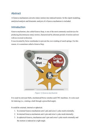
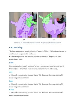
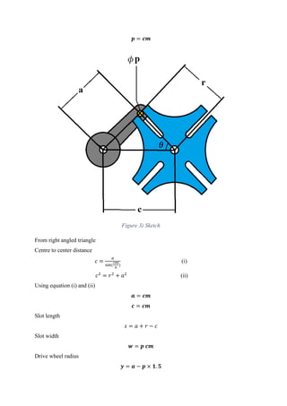
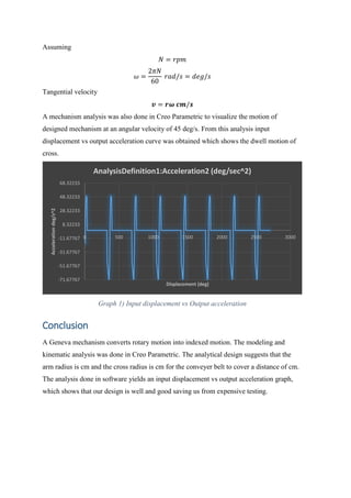
External Geneva Mechanism
MEMBERS:
Hamza Nawaz CU-369-2017
Muhammad Abbas CU-388-2017
Arbab Karim CU-374-2017
Fahad Fazal Wahid CU-378-2016
Submitted to:
Engr. Hasim Khan
Supervisor:
Sir Shafi Ullah
Department of Mechanical Engineering
CECOS University of IT & Emerging Sciences
Abstract
A Geneva mechanism converts rotary motion into indexed motion. In this report modeling,
analytical analysis and kinematic analysis of a Geneva mechanism is included.
Introduction
Geneva mechanism, also called Geneva Stop, is one of the most commonly used devices for
producing discontinuous rotary motion, characterized by alternate periods of motion and rest
with no reversal in direction.
It was invented by Swiss watchmaker to prevent the over winding of watch springs. For this
reason, it is sometimes called a Geneva Stop.
Figure 1) Geneva mechanism
It is used in conveyer belts, mechanical/Swiss watches and CNC machines. It is also used
for indexing (i.e., rotating a shaft through a prescribed angle).
It could be external, internal or spherical.
1. In external Geneva mechanism arm’s pin and cross’s yoke mesh externally.
2. In internal Geneva mechanism arm’s pin and cross’s yoke mesh internally.
3. In spherical Geneva, mechanism arm’s pin and cross’s yoke mesh externally and
the motion is indexed at a right angle.
Figure 2) (a) Internal Geneva mechanism (b) Spherical Geneva mechanism
CAD Modeling
The Geneva mechanism is modeled in Creo Parametric 7.0.0.0 a CAD software, in order to
do a kinematic analysis on this mechanism.
CAD modeling includes part modeling and then assembling all the parts with right
connections or joints.
Parts
Geneva mechanism typically consists of an arm, a base, a driven wheel (cross in case of
four slots) and a drive wheel. Their modeling is described below individually,
Arm
A 2D sketch was made using lines and circles. This sketch was then converted to a 3D
model using extrude command.
Base
A 2D sketch was made using lines and circles. This sketch was then converted to a 3D
model using extrude command.
Cross
A 2D sketch was made using lines and circles. This sketch was then converted to a 3D
model using extrude command.
Drive wheel
A 2D sketch was made using lines and circles. This sketch was then converted to a 3D
model using extrude command.
Assembly
Assembly process was completed in three steps.
1. Drive wheel was fixed and arm was assembled to the hole axis of drive wheel. The
connection used was coincident.
2. Base was fixed and cross was assembled to one of its pin using a pin connection in
a separate assembly file.
3. The drive wheel and arm assembly was then connected through a pin connection to
the second pin of the base. Assembly was completed by defining a 3D contact
between pin of the arm that was taken as a reference and all four slots/yokes of the
cross.
Analysis
In the design, process of this external Geneva mechanism a kinematic analysis was done to
complete the design. Analytical calculations of the analysis are given below,
A conveyer belt is to be moved at a fixed distance after a fixed interval of time. For this
purpose, a Geneva mechanism is designed. The distance moved by the conveyer belt and
cross is always same.
Let distance moved by cross is
s = 𝑐𝑚
Let no. of slots on cross
n = 4
So
1 𝑑𝑟𝑖𝑣𝑒 𝑤ℎ𝑒𝑒𝑙 𝑟𝑜𝑡𝑎𝑡𝑖𝑜𝑛 = ¼ 𝑟𝑜𝑡𝑎𝑡𝑖𝑜𝑛 𝑜𝑓 𝑐𝑟𝑜𝑠𝑠
So, the angle covered by cross is
360
4
= 90 = 0.5𝜋
As
𝑠 = 𝑟𝜃
𝒓 = 𝒄𝒎
Assume pin diameter
𝒑 = 𝒄𝒎
Figure 3) Sketch
From right angled triangle
Centre to center distance
𝑐 =
𝑎
sin(
180
𝑛
)
(i)
𝑐2
= 𝑟2
+ 𝑎2
(ii)
Using equation (i) and (ii)
𝒂 = 𝒄𝒎
𝒄 = 𝒄𝒎
Slot length
𝑠 = 𝑎 + 𝑟 − 𝑐
Slot width
𝒘 = 𝒑 𝒄𝒎
Drive wheel radius
𝒚 = 𝒂 − 𝒑 × 𝟏. 𝟓
Assuming
𝑁 = 𝑟𝑝𝑚
𝜔 =
2𝜋𝑁
60
𝑟𝑎𝑑/𝑠 = 𝑑𝑒𝑔/𝑠
Tangential velocity
𝒗 = 𝒓𝝎 𝒄𝒎/𝒔
A mechanism analysis was also done in Creo Parametric to visualize the motion of
designed mechanism at an angular velocity of 45 deg/s. From this analysis input
displacement vs output acceleration curve was obtained which shows the dwell motion of
cross.
Graph 1) Input displacement vs Output acceleration
Conclusion
A Geneva mechanism converts rotary motion into indexed motion. The modeling and
kinematic analysis was done in Creo Parametric. The analytical design suggests that the
arm radius is cm and the cross radius is cm for the conveyer belt to cover a distance of cm.
The analysis done in software yields an input displacement vs output acceleration graph,
which shows that our design is well and good saving us from expensive testing.
-71.67767
-51.67767
-31.67767
-11.67767
8.32233
28.32233
48.32233
68.32233
0 500 1000 1500 2000 2500 3000
Acceleration
deg/s^2
Displacement (deg)
AnalysisDefinition1:Acceleration2 (deg/sec^2)

External geneva mechanism mini project report

  • 1.
    External Geneva Mechanism MEMBERS: HamzaNawaz CU-369-2017 Muhammad Abbas CU-388-2017 Arbab Karim CU-374-2017 Fahad Fazal Wahid CU-378-2016 Submitted to: Engr. Hasim Khan Supervisor: Sir Shafi Ullah Department of Mechanical Engineering CECOS University of IT & Emerging Sciences
  • 2.
    Abstract A Geneva mechanismconverts rotary motion into indexed motion. In this report modeling, analytical analysis and kinematic analysis of a Geneva mechanism is included. Introduction Geneva mechanism, also called Geneva Stop, is one of the most commonly used devices for producing discontinuous rotary motion, characterized by alternate periods of motion and rest with no reversal in direction. It was invented by Swiss watchmaker to prevent the over winding of watch springs. For this reason, it is sometimes called a Geneva Stop. Figure 1) Geneva mechanism It is used in conveyer belts, mechanical/Swiss watches and CNC machines. It is also used for indexing (i.e., rotating a shaft through a prescribed angle). It could be external, internal or spherical. 1. In external Geneva mechanism arm’s pin and cross’s yoke mesh externally. 2. In internal Geneva mechanism arm’s pin and cross’s yoke mesh internally. 3. In spherical Geneva, mechanism arm’s pin and cross’s yoke mesh externally and the motion is indexed at a right angle.
  • 3.
    Figure 2) (a)Internal Geneva mechanism (b) Spherical Geneva mechanism CAD Modeling The Geneva mechanism is modeled in Creo Parametric 7.0.0.0 a CAD software, in order to do a kinematic analysis on this mechanism. CAD modeling includes part modeling and then assembling all the parts with right connections or joints. Parts Geneva mechanism typically consists of an arm, a base, a driven wheel (cross in case of four slots) and a drive wheel. Their modeling is described below individually, Arm A 2D sketch was made using lines and circles. This sketch was then converted to a 3D model using extrude command. Base A 2D sketch was made using lines and circles. This sketch was then converted to a 3D model using extrude command. Cross A 2D sketch was made using lines and circles. This sketch was then converted to a 3D model using extrude command.
  • 4.
    Drive wheel A 2Dsketch was made using lines and circles. This sketch was then converted to a 3D model using extrude command. Assembly Assembly process was completed in three steps. 1. Drive wheel was fixed and arm was assembled to the hole axis of drive wheel. The connection used was coincident. 2. Base was fixed and cross was assembled to one of its pin using a pin connection in a separate assembly file. 3. The drive wheel and arm assembly was then connected through a pin connection to the second pin of the base. Assembly was completed by defining a 3D contact between pin of the arm that was taken as a reference and all four slots/yokes of the cross. Analysis In the design, process of this external Geneva mechanism a kinematic analysis was done to complete the design. Analytical calculations of the analysis are given below, A conveyer belt is to be moved at a fixed distance after a fixed interval of time. For this purpose, a Geneva mechanism is designed. The distance moved by the conveyer belt and cross is always same. Let distance moved by cross is s = 𝑐𝑚 Let no. of slots on cross n = 4 So 1 𝑑𝑟𝑖𝑣𝑒 𝑤ℎ𝑒𝑒𝑙 𝑟𝑜𝑡𝑎𝑡𝑖𝑜𝑛 = ¼ 𝑟𝑜𝑡𝑎𝑡𝑖𝑜𝑛 𝑜𝑓 𝑐𝑟𝑜𝑠𝑠 So, the angle covered by cross is 360 4 = 90 = 0.5𝜋 As 𝑠 = 𝑟𝜃 𝒓 = 𝒄𝒎 Assume pin diameter
  • 5.
    𝒑 = 𝒄𝒎 Figure3) Sketch From right angled triangle Centre to center distance 𝑐 = 𝑎 sin( 180 𝑛 ) (i) 𝑐2 = 𝑟2 + 𝑎2 (ii) Using equation (i) and (ii) 𝒂 = 𝒄𝒎 𝒄 = 𝒄𝒎 Slot length 𝑠 = 𝑎 + 𝑟 − 𝑐 Slot width 𝒘 = 𝒑 𝒄𝒎 Drive wheel radius 𝒚 = 𝒂 − 𝒑 × 𝟏. 𝟓
  • 6.
    Assuming 𝑁 = 𝑟𝑝𝑚 𝜔= 2𝜋𝑁 60 𝑟𝑎𝑑/𝑠 = 𝑑𝑒𝑔/𝑠 Tangential velocity 𝒗 = 𝒓𝝎 𝒄𝒎/𝒔 A mechanism analysis was also done in Creo Parametric to visualize the motion of designed mechanism at an angular velocity of 45 deg/s. From this analysis input displacement vs output acceleration curve was obtained which shows the dwell motion of cross. Graph 1) Input displacement vs Output acceleration Conclusion A Geneva mechanism converts rotary motion into indexed motion. The modeling and kinematic analysis was done in Creo Parametric. The analytical design suggests that the arm radius is cm and the cross radius is cm for the conveyer belt to cover a distance of cm. The analysis done in software yields an input displacement vs output acceleration graph, which shows that our design is well and good saving us from expensive testing. -71.67767 -51.67767 -31.67767 -11.67767 8.32233 28.32233 48.32233 68.32233 0 500 1000 1500 2000 2500 3000 Acceleration deg/s^2 Displacement (deg) AnalysisDefinition1:Acceleration2 (deg/sec^2)