Download to read offline
![Frequency Domain.
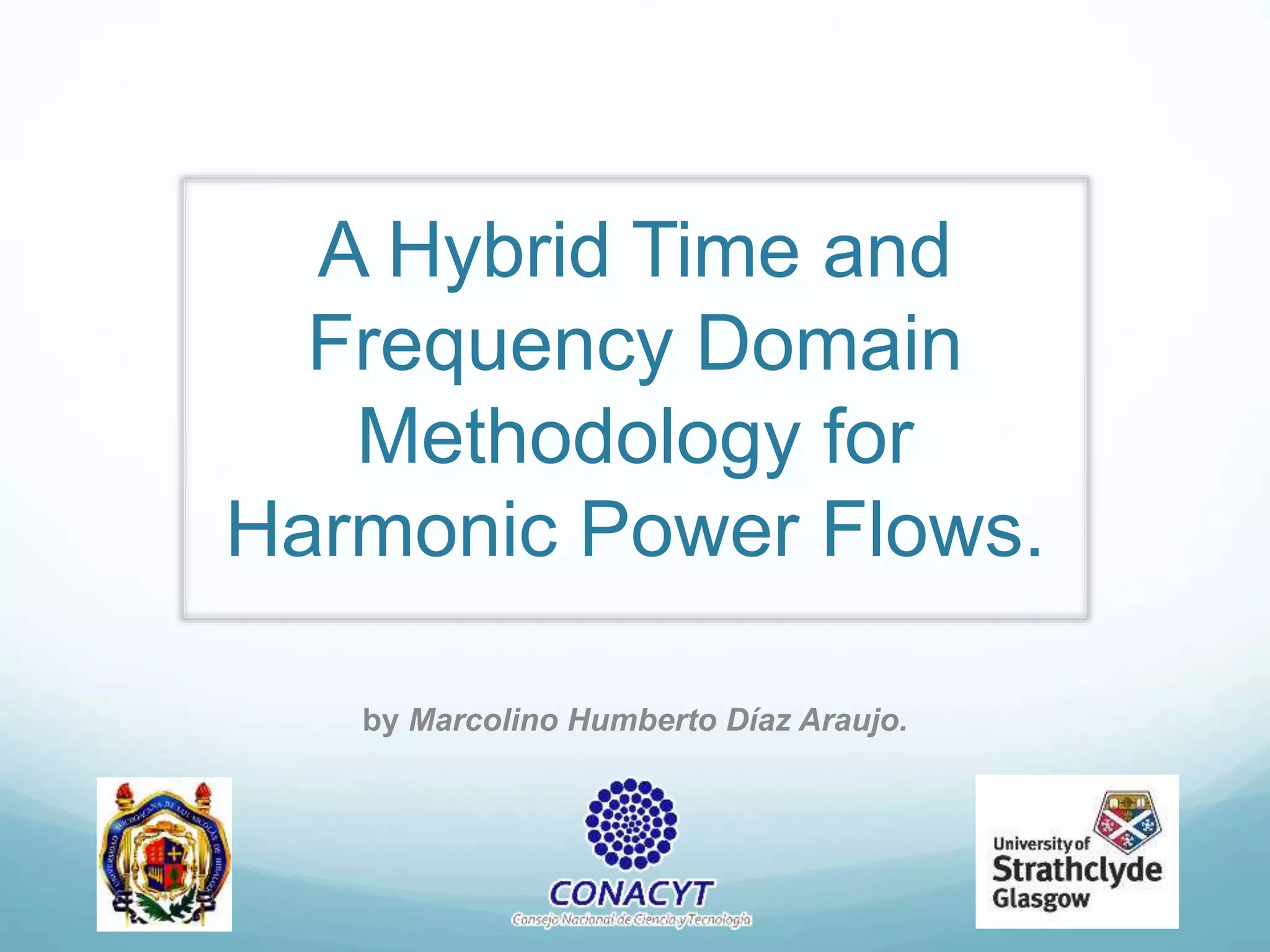
In general, available methods for harmonic analysis in the
frequency domain are divided into:
1. Direct Method.
[Yh] Vh = Ih.
1. Iterative Harmonic Analysis.
2. Harmonic Power Flow Methods.](https://image.slidesharecdn.com/expounitedking-160504201713/85/Expo-unitedking-4-320.jpg)
![The iterative solution for the entire system has the form
Yh [ΔV] = ΔI
where
ΔI = IL + INL
IL = YhVh
INL is obtained by the time domain simulation](https://image.slidesharecdn.com/expounitedking-160504201713/85/Expo-unitedking-7-320.jpg)
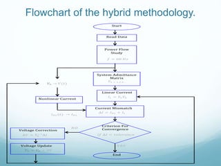
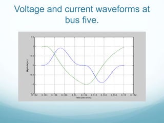
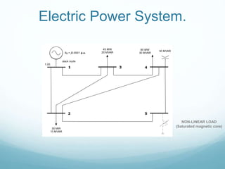
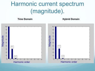
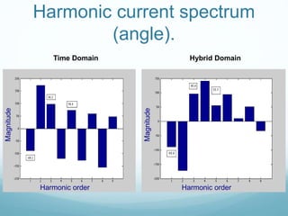


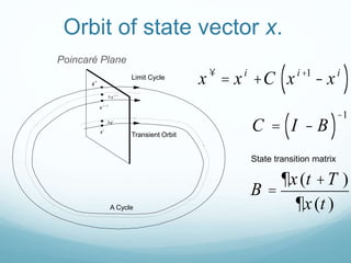
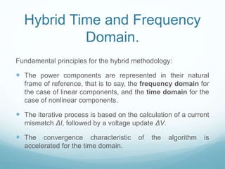
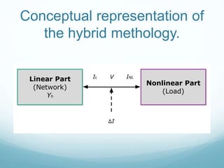
This document presents a hybrid time and frequency domain methodology for harmonic power flow analysis. The methodology represents power components in their natural frame of reference, with linear components in the frequency domain and nonlinear components in the time domain. It uses an iterative process of calculating a current mismatch and updating voltages. The hybrid approach accelerates convergence for the time domain simulation compared to conventional time domain solutions. Future work may apply parallel processing, control harmonic propagation, incorporate additional nonlinear components, and extend the methodology to three-phase systems.

![[Paper reading] Hamiltonian Neural Networks](https://cdn.slidesharecdn.com/ss_thumbnails/hamiltoniannn-200131102421-thumbnail.jpg?width=640&height=640&fit=bounds)

![Sensor Fusion Study - Ch3. Least Square Estimation [강소라, Stella, Hayden]](https://cdn.slidesharecdn.com/ss_thumbnails/chapter3-200521130800-thumbnail.jpg?width=640&height=640&fit=bounds)


