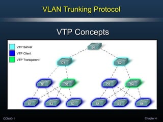
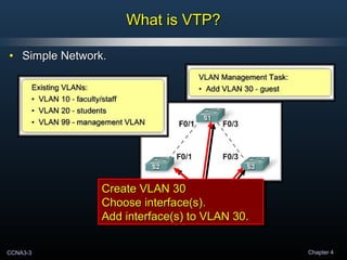
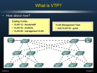
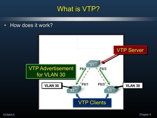
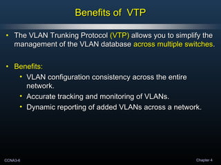
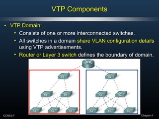
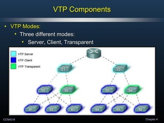
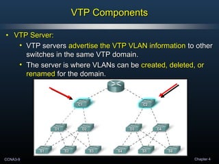
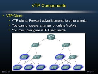
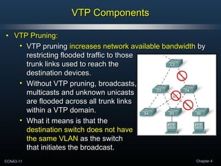
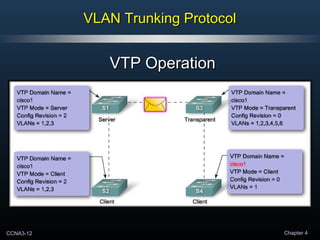
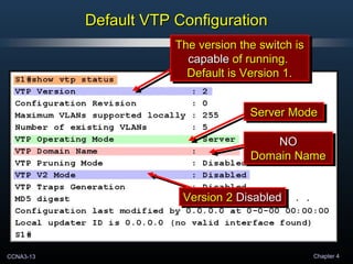
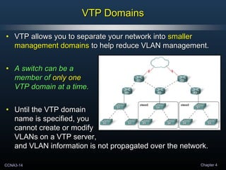
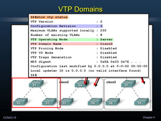
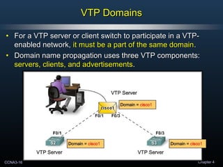
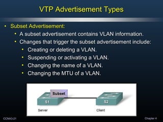
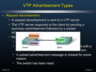
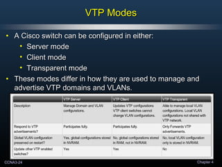
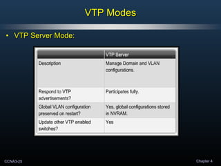
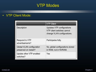
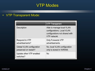
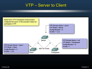
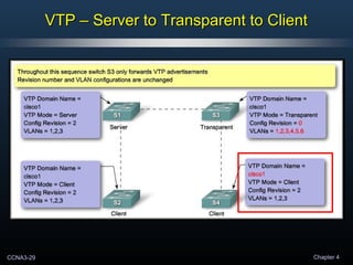
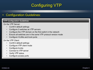
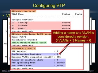
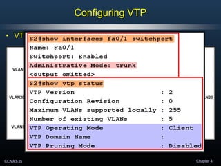
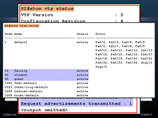
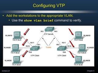
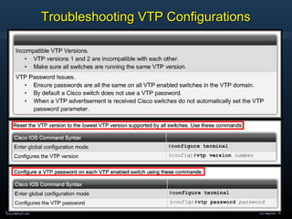
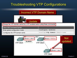
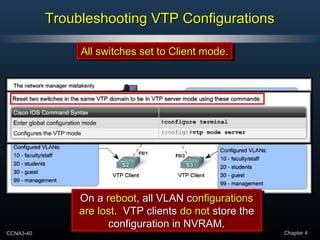
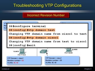
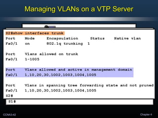
VTP allows VLAN configurations to be synchronized across multiple switches, simplifying network management. It operates by electing a switch as the VTP server, where VLANs can be created and modified. This information is then propagated through VTP advertisements to other switches operating as clients or in transparent mode. Troubleshooting may involve checking the VTP domain name, revision number, and that at least one switch is operating as a server.
VLANs logically segment a network into separate broadcast domains to improve security, performance, and manageability. VLANs use frame tagging to identify which VLAN a frame belongs to. The two main frame tagging protocols are Cisco's proprietary ISL protocol and the open standard IEEE 802.1Q protocol. A VLAN port can be either an access port assigned to one VLAN or a trunk port that can carry multiple VLAN traffic between switches.
The document discusses Virtual Trunking Protocol (VTP). It describes VTP as a Cisco proprietary protocol that exchanges VLAN information across trunk links, allowing network managers to distribute VLAN configurations to all switches in the same domain. The document outlines the key components of VTP, including domains, advertisements, and pruning. It also details the different VTP modes of server, client, and transparent and how they operate. The benefits of using VTP for VLAN management are presented, along with some common VTP configuration issues.
This document discusses VLAN Trunking Protocol (VTP) which allows switches to exchange VLAN configuration information and manage VLANs across multiple switches. It describes VTP domains, modes, advertisements and pruning. VTP is configured on switches to synchronize VLAN information and eliminate incorrect configurations. Troubleshooting tools like "show vtp status" and "show interfaces trunk" are used to verify proper VTP configuration and trunking.
VTP allows for synchronization of VLAN information between switches to reduce administration. It uses advertisements sent over trunk links to exchange VLAN configuration details. A switch can be configured as a VTP server to manage VLANs for a domain, as a client to receive updates, or as transparent to only use local VLAN data. VTP pruning helps optimize traffic flow by restricting broadcasts only to necessary trunks.
VTP is used to distribute and synchronize VLAN information throughout a switched network. Switches can operate in server, client, or transparent mode. Server switches can create and modify VLANs, while clients and transparent switches can only modify VLANs locally. VTP pruning conserves bandwidth by not flooding VLAN traffic to ports that are not assigned to that VLAN. The show vtp commands are used to verify and troubleshoot the VTP configuration.
- VLAN Trunking Protocol (VTP) allows VLAN configurations to be consistently maintained across a common administrative domain to reduce complexity and inconsistencies when changes are made. VTP advertisements containing VLAN information are transmitted over trunk links and switches inherit the sending switch's VTP domain name. VTP uses revision numbers, starting at 0 and incrementing with each change, to determine if received information is more recent than the local configuration.
The document discusses VLAN Trunking Protocol (VTP), which allows VLAN configurations to be automatically propagated across multiple switches to reduce configuration errors and maintenance. VTP operates by defining a VTP domain where one switch acts as a server to send VLAN information to other client switches. It describes how VTP advertisements are sent and processed to update switches when VLANs are added or modified on the server. The roles of server, client, and transparent modes are also outlined.
This document provides instructions for configuring VTP (VLAN Trunking Protocol) on a switched network. The tasks include:
1. Configuring S1 as the VTP server with domain CCNA and password cisco.
2. Configuring S2 and S3 as VTP clients in the same domain.
3. Creating VLANs 10, 20, 30, 99 on S1 which are then distributed to S2 and S3 via VTP.
4. Configuring trunk links between the switches and assigning VLANs to access ports on S2 and S3.
5. Verifying the VTP configuration and VLAN implementation through connectivity tests between PCs.
LAN Switching and Wireless: Ch4 - VLAN Trunking Protocol (VTP)Abdelkhalik Mosa
This document discusses the VLAN Trunking Protocol (VTP). VTP allows network managers to centrally manage VLAN configurations across multiple switches in a domain. It maintains consistency by propagating VLAN changes between switches. The document covers VTP domains, advertisements, modes, pruning, configuration and troubleshooting.
The document discusses VLAN tagging, trunking, DTP, and inter-VLAN routing. It provides information on:
1) VLAN tagging which allows a single link to carry traffic for more than one VLAN by adding a unique packet identifier within each header to designate the VLAN membership of each packet.
2) Methods of frame tagging including Cisco's ISL and IEEE 802.1Q standards.
3) Configuring trunking on interfaces using commands like switchport trunk encapsulation and switchport mode trunk.
4) Dynamic Trunking Protocol (DTP) and its various trunking modes like desirable, auto and trunk that allow interfaces to automatically or manually negotiate trunk links.
This document discusses VLANs and trunking in converged networks. It explains that VLANs logically group devices to segment broadcast domains, reducing costs and improving security and performance. Types of VLAN traffic include data, voice, and network protocols. Communication between VLANs requires routers. Trunks are used for intra-VLAN communication and use 802.1Q tagging to identify frame VLANs, without tagging the native VLAN. The document also covers configuring and troubleshooting VLANs and trunks on Cisco switches.
VLANs logically segment a local area network (LAN) into separate broadcast domains to limit broadcast traffic and provide additional security. A VLAN uses switches to create isolated network segments and define broadcast domains without changing the physical cabling. VLANs offer benefits like limiting broadcast domains, increased security by separating users, and flexibility to change user assignments by reconfiguring ports on switches instead of moving cables.
Virtual Local Area Network (VLAN) provide a way of grouping different network devices to ensure that those devices can communicate directly with one another.
- Port-based VLANs are commonly used today, where a port is associated with a VLAN.
- Data VLANs carry only user traffic, separating it from voice and management traffic. The default VLAN on Cisco switches is VLAN 1.
- A native VLAN is assigned to trunk ports to handle untagged traffic using VLAN 99 as an example. A management VLAN like VLAN 99 provides switch management access. Voice VLANs use a separate VLAN like VLAN 150 to ensure quality of voice traffic.
VLAN allows logical separation of broadcast domains by tagging Ethernet frames with VLAN IDs. It divides a physical network into virtual LANs to improve security, manageability and flexibility. VLAN configuration involves assigning ports to VLANs either statically by port number or dynamically by MAC address. Frame tagging standards like IEEE 802.1Q are used to identify VLANs on trunk links that carry traffic for multiple VLANs between switches.
VLANs are virtual broadcast domains that segment traffic on a layer 2 network. Each VLAN is like a separate virtual bridge within a switch. VLANs can span multiple switches using trunk links, which carry traffic for multiple VLANs. ISL is a Cisco proprietary protocol that maintains VLAN information as traffic passes between switches, allowing traffic to enter the correct VLAN. It functions at layer 2 and adds a 30 byte header to each frame. VTP maintains VLAN configuration consistency across switches by propagating changes to all switches in a VTP domain.
VLANs logically divide the LAN into separate broadcast domains without using routers. Switches with VLAN capability allow ports to be configured as access, trunk, or general ports. Access ports belong to one VLAN and use untagged frames. Trunk ports can belong to multiple VLANs and use tagged frames, with a native VLAN using untagged frames. Ingress filtering ensures frames are tagged with an associated VLAN.
This document discusses inter-VLAN routing and two common methods: using a router on a stick configuration or an internal router within a multilayer switch. With a router on a stick, subinterfaces are used to separate VLANs on the router and 802.1Q trunking passes traffic between VLANs. Alternatively, some switches have an internal router module that can perform inter-VLAN routing without subinterfaces by configuring VLAN routing and trunking interfaces. The document provides examples of configuring both approaches and discusses their application in campus network designs.
Inter-VLAN routing is the process of forwarding network traffic from one VLAN to another VLAN using a
router.
VLANs divide broadcast domains in a LAN environment. Whenever hosts in one VLAN need to
communicate with hosts in another VLAN, the traffic must be routed between them. This is known as
inter-VLAN routing. On Catalyst switches it is accomplished by creating Layer 3 interfaces (Switch virtual
interfaces (SVI)).
Virtual LANs (VLANs) logically segment a network into broadcast domains to restrict communication between devices. VLANs group devices by function, department, application or other criteria without regard to physical location. Routers provide connectivity between VLAN segments. Implementing VLANs on a switch creates separate bridging tables for each VLAN so frames are only switched between ports in the same VLAN. VLANs improve security, flexibility and management of the network compared to relying solely on physical segmentation.
VLANs logically segment LANs into broadcast domains by using switches to assign ports and their attached devices to VLAN groups based on their MAC address, IP subnet, or switch port. This allows devices that are physically located on different floors or buildings to belong to the same logical LAN segment while preventing Layer 2 broadcasts from crossing VLAN boundaries. VLAN trunk links between switches allow multiple VLANs to be transmitted over the same physical link.
This document discusses VLANs and trunking in converged networks. It begins by explaining the objectives and then defines VLANs, describing how they segment broadcast domains and reduce costs. It also discusses trunking, how trunks allow communication between VLANs using tagging, and common trunking protocols. Finally, it addresses configuring and troubleshooting VLANs and trunks on Cisco switches.
VXLAN allows overlaying of layer 2 networks over a layer 3 underlay network using IP routing. It creates virtual networks by encapsulating layer 2 frames in UDP packets which are transported via the layer 3 network. This provides up to 16 million virtual networks compared to 4000 with VLAN. VXLAN is used for virtual machine migration across data centers, disaster recovery, and network virtualization in the cloud. It works by having VXLAN tunnel end points encapsulate and de-encapsulate frames between virtual networks identified by VXLAN network identifiers.
The document discusses VLAN configuration for a group project. It defines VLAN as a broadcast domain within a switch that divides a broadcast domain into multiple broadcast domains. It provides details on LANs, creating VLANs, VLAN types (static and dynamic), and commands used for VLAN configuration like show vlan brief, vlan database, and switchport access vlan. Benefits of VLAN discussed are broadcast control, security, and performance.
This chapter will cover how to configure, manage, and troubleshoot VLANs and
VLAN trunks. It will also examine security considerations and strategies relating
to VLANs and trunks, and best practices for VLAN design.
in the slide we discuss - VLAN overview, effectiveness, benefits, how VLAN work, memberships mode, operations, creation Guidelines, add VLAN, accessing,managing and verifying .
This document describes virtual local area networks (VLANs), how they work, and their advantages over traditional LANs. It discusses how VLANs allow logical segmentation of networks without requiring physical relocation of devices. VLANs use tagging of frames to associate them with broadcast domains, avoiding the need for routers in many cases. This reduces costs and improves performance by limiting unnecessary broadcast traffic compared to traditional LANs.
The document discusses strategies for scaling VLANs and troubleshooting inter-VLAN routing, including configuring VTP, DTP, extended VLANs, and Layer 3 switching. It provides instructions for configuring VTP servers and clients, creating and assigning VLANs, configuring trunks, and addresses common issues like misconfigured switch ports, IP addresses, and VTP/DTP settings. The objectives are to configure inter-switch connectivity technologies, troubleshoot inter-VLAN routing environments, and understand concepts like VTP advertisements, modes, and versions.
This document outlines the objectives and content covered in Chapter 2 of the CCNA Routing and Switching Scaling Networks course. The chapter covers scaling VLANs through technologies like VTP, extended VLANs, DTP, and layer 3 switching. Specific topics covered include configuring and troubleshooting VTP versions 1 and 2, extended VLANs, DTP, multi-VLAN routing issues, and layer 3 switching for inter-VLAN routing.
VLANs logically segment a network into broadcast domains. VLANs are defined at Layer 2 and use VLAN tags in frame headers. VTP automates VLAN configuration across switches by propagating updates in a VTP domain. Switches can operate as VTP servers, clients, or transparently. Servers control the VLAN database while clients rely on servers and transparent switches do not directly participate.
This document describes how to configure VTP and VLANs on Cisco switches. It discusses:
- How VTP works to synchronize VLAN configurations across switches in a VTP domain.
- Configuring a switch as a VTP server to propagate VLAN changes to other switches, or as a VTP client which receives but does not change VLAN configurations.
- Default VTP settings and guidelines for implementing VTP in a network.
Configure VLANs on Catalyst switches that run CatOS or Cisco IOS software by:
1. Creating VLANs and assigning ports to them by setting the VTP domain and mode, then using the set vlan command.
2. Removing ports from VLANs or deleting VLANs entirely using commands like reset vlan, set vlan, and unset vlan.
3. Troubleshooting VLAN configuration issues using show commands to check VLAN assignments and VTP configuration. The document provides sample commands for configuring VLANs on different Catalyst switch models.
This document discusses VLAN Trunking Protocol (VTP) which allows switches to exchange VLAN configuration information and manage VLANs across multiple switches. It describes VTP domains, modes, advertisements and pruning. VTP is configured on switches to distribute VLAN information throughout a converged network and troubleshoot configuration issues. Proper VTP configuration ensures switches within the same VTP domain automatically update to reflect any new VLANs or changes made to existing VLANs.
VLANs logically group users and resources together without being restricted by physical network segments. There are static and dynamic VLANs, with static VLAN port assignments always remaining fixed while dynamic VLANs are created through management software. Frame tagging allows VLANs to span multiple switches by uniquely assigning a VLAN ID to each frame. The VLAN Trunking Protocol (VTP) manages VLAN configurations across switches to provide benefits like consistent VLAN setup, accurate monitoring, and dynamic reporting of new VLANs. Configuring VLANs involves creating VLANs, assigning switch ports, configuring trunk ports between switches, and setting up inter-VLAN routing using subinterfaces on a router interface.
Virtual LANs (VLANs) logically segment a network to increase performance and security. VLANs can be static or dynamic and identify devices using frame tagging. VLAN trunking protocol (VTP) manages VLAN configurations across switches and has different modes like server, client, and transparent. VLANs are configured by creating them, assigning ports, setting up trunks, and configuring inter-VLAN routing. Troubleshooting involves checking the VTP status to ensure all switches are in the same domain and have the correct configuration revision.
The document contains information about VLAN Trunk Protocol (VTP) including configuration settings and modes. It provides 20 multiple choice questions about VTP with answers.
Ch4 ccna exploration 3 lan switching and wirelesskratos2424
VTP dynamically communicates VLAN changes to all switches in the same VTP domain. Switches must be configured with the same VTP domain name, mode, revision number, and version number to participate in the same VTP domain and synchronize VLAN information. A switch with a lower revision number will update to the higher revision number, synchronizing VLAN configurations.
VLAN Trunking Protocol (VTP) allows switches to share VLAN information across the network. VTP maintains consistency by propagating VLAN changes from one switch to other switches in the same VTP management domain. Trunk links connect switches and support multiple VLANs by tagging frames with 802.1Q encapsulation or Cisco's ISL protocol. This allows VLAN traffic to traverse the trunk between switches while maintaining separation of packets for different VLANs.
VLAN Trunking Protocol (VTP) reduces administration by automatically distributing VLAN configurations throughout a domain of switches. VTP operates in server, client, transparent, or off modes. VTP servers can create and modify VLANs, while clients and transparent switches can only forward VTP advertisements. VTP pruning helps reduce unnecessary broadcast traffic by pruning VLANs from trunks where no end stations exist. VTP version 3 supports extended VLAN ranges and private VLANs, while offering more secure authentication and compatibility with version 2.
- The document describes how to create VLANs on Cisco Catalyst switches running CatOS and on Catalyst 2900 XL, 3500 XL, 2950, and 3550 series switches.
- The first step is to configure the VTP domain name and mode on the switch to be either server or transparent. Then VLANs can be created using the set vlan command.
- Ports are assigned to VLANs using the set vlan command followed by the VLAN number and module/port numbers. The show vlan command verifies VLAN configurations.
The document provides instructions for creating VLANs on Cisco Catalyst switches running CatOS and on Catalyst 2900 XL, 3500 XL, 2950, and 3550 series switches. It discusses important notes about VLANs and their configuration including VTP domain settings. Steps are outlined for configuring the VLAN, verifying the configuration, and troubleshooting. Related documentation is also referenced.
1) The document discusses primary VLANs on HP Procurve Series 2500 switches. The primary VLAN performs important functions like managing the switch's IP address and learning the default gateway.
2) By default, the primary VLAN is the default VLAN with VLAN ID 1, but any VLAN can be configured as the primary. The primary VLAN must connect all stack members and candidates.
3) If a switch does not learn the expected default gateway or Timep server from DHCP, the primary VLAN setting should be checked to ensure it is connected to the providing server.
This document discusses configuring VLANs on Cisco switches. It covers VLAN configuration topics like configuring VTP, creating and modifying VLANs, assigning ports to VLANs, configuring trunking, and troubleshooting VLAN issues. The document provides examples of Cisco IOS commands used to configure these features on Catalyst 1900 and Catalyst 2950 switches. It also describes show commands used to verify proper VLAN, VTP, and trunking operation.
VLAN Trunking Protocol (VTP) is a Cisco proprietary protocol that propagates the definition of Virtual
Local Area Networks (VLAN) on the whole local area network.[1] To do this, VTP carries VLAN
information to all the switches in a VTP domain. VTP advertisements can be sent over ISL, 802.1Q, IEEE
802.10 and LANE trunks. VTP is available on most of the Cisco Catalyst Family products.
This chapter discusses VLAN trunking protocols (VTP), dynamic trunking protocol (DTP), and EtherChannel bundles. VTP allows VLAN configurations to be propagated across switches to reduce provisioning burden, while DTP dynamically establishes trunk links between switches. EtherChannel bundles multiple physical links into a single logical trunk to increase bandwidth and provide redundancy.
Bab 7-1 membahas tentang jarak antara titik A dan P yang sama dengan jarak antara titik B dan P dengan mengubah nilai panjang gelombang. Persamaan dijelaskan untuk menghitung nilai maksimum radius zon Fresnel pertama dengan mengkonversi frekuensi dan jarak total ke GHz dan Km. Diuraikan pula tentang grid antenna vertikal dan horizontal serta gelombang vertikal dan horizontal. Terakhir dijelaskan tentang radio point to point tanpa gangguan dan dengan gangguan p
This document discusses basic concepts of wireless networking and wireless LAN configuration. It begins by explaining how wireless networking allows for mobile productivity as users can access the network from any location. It then discusses why wireless networking is used, including flexibility and reduced costs compared to wired networks. Finally, it covers wireless LAN components like wireless access points that connect wireless clients to the wired LAN, and wireless network interface cards that allow devices to connect to the network wirelessly.
This document discusses inter-VLAN routing and different methods for implementing it. It introduces inter-VLAN routing as a process of forwarding traffic between VLANs using a router. There are three main methods discussed: traditional routing using one interface per VLAN, router-on-a-stick using subinterfaces on a single router interface, and switch-based routing using switch virtual interfaces. The document provides detailed explanations and configurations for router-on-a-stick inter-VLAN routing.
Redundant layer 2 topologies can create loops in the network. Spanning Tree Protocol (STP) controls this by logically blocking ports on switches to ensure only a single path exists between devices. STP elects a root bridge and designates root, designated and blocked ports to break up loops while maintaining connectivity. It prevents issues like broadcast storms and duplicate unicast frames that can occur due to loops in the network.
VLAN trunking allows traffic from multiple VLANs to travel across the same link between two switches. This reduces the number of required physical links and saves on infrastructure costs. VLAN trunks use tagging to identify which VLAN each frame belongs to as switches forward frames based on MAC addresses only. Common trunking modes are 802.1Q, which is now the standard, and ISL, which was used in older Cisco switches but is no longer recommended. Dynamic Trunking Protocol (DTP) can be used to automatically negotiate trunking settings between switches.
Dokumen tersebut membahas tentang VLAN (Virtual Local Area Network) yang merupakan teknologi jaringan untuk membagi logis jaringan switch menjadi beberapa subnet virtual. VLAN memungkinkan pembagian jaringan berdasarkan fungsi, tim proyek, aplikasi, atau koneksi ke jaringan lain. Komunikasi antar VLAN memerlukan router namun hanya membutuhkan satu koneksi fisik. Dokumen juga menjelaskan tipe-tipe VLAN seperti data VLAN, default VLAN
This document discusses key concepts of Ethernet and switch configuration. It describes Ethernet frame formats, MAC addresses, switch port settings including auto-negotiation and auto-MDIX. It explains how switches use MAC address tables to forward traffic, providing examples of entries being added to the table. Design considerations for Ethernet like bandwidth and collisions are also covered.
This document discusses switch security configuration and common security attacks. It covers topics such as configuring passwords, console access, virtual terminal access, banners, telnet/SSH, and port security. Various security attacks are also described like MAC address flooding, spoofing attacks, CDP attacks, and telnet attacks. The document provides configuration examples for securing switch access and interfaces using passwords, banners, telnet/SSH, and port security features.
Dr. Sean Tan, Head of Data Science, Changi Airport Group
Discover how Changi Airport Group (CAG) leverages graph technologies and generative AI to revolutionize their search capabilities. This session delves into the unique search needs of CAG’s diverse passengers and customers, showcasing how graph data structures enhance the accuracy and relevance of AI-generated search results, mitigating the risk of “hallucinations” and improving the overall customer journey.
Why You Should Replace Windows 11 with Nitrux Linux 3.5.0 for enhanced perfor...SOFTTECHHUB
The choice of an operating system plays a pivotal role in shaping our computing experience. For decades, Microsoft's Windows has dominated the market, offering a familiar and widely adopted platform for personal and professional use. However, as technological advancements continue to push the boundaries of innovation, alternative operating systems have emerged, challenging the status quo and offering users a fresh perspective on computing.
One such alternative that has garnered significant attention and acclaim is Nitrux Linux 3.5.0, a sleek, powerful, and user-friendly Linux distribution that promises to redefine the way we interact with our devices. With its focus on performance, security, and customization, Nitrux Linux presents a compelling case for those seeking to break free from the constraints of proprietary software and embrace the freedom and flexibility of open-source computing.
UiPath Test Automation using UiPath Test Suite series, part 5DianaGray10
Welcome to UiPath Test Automation using UiPath Test Suite series part 5. In this session, we will cover CI/CD with devops.
Topics covered:
CI/CD with in UiPath
End-to-end overview of CI/CD pipeline with Azure devops
Speaker:
Lyndsey Byblow, Test Suite Sales Engineer @ UiPath, Inc.
Introducing Milvus Lite: Easy-to-Install, Easy-to-Use vector database for you...Zilliz
Join us to introduce Milvus Lite, a vector database that can run on notebooks and laptops, share the same API with Milvus, and integrate with every popular GenAI framework. This webinar is perfect for developers seeking easy-to-use, well-integrated vector databases for their GenAI apps.
UiPath Test Automation using UiPath Test Suite series, part 6DianaGray10
Welcome to UiPath Test Automation using UiPath Test Suite series part 6. In this session, we will cover Test Automation with generative AI and Open AI.
UiPath Test Automation with generative AI and Open AI webinar offers an in-depth exploration of leveraging cutting-edge technologies for test automation within the UiPath platform. Attendees will delve into the integration of generative AI, a test automation solution, with Open AI advanced natural language processing capabilities.
Throughout the session, participants will discover how this synergy empowers testers to automate repetitive tasks, enhance testing accuracy, and expedite the software testing life cycle. Topics covered include the seamless integration process, practical use cases, and the benefits of harnessing AI-driven automation for UiPath testing initiatives. By attending this webinar, testers, and automation professionals can gain valuable insights into harnessing the power of AI to optimize their test automation workflows within the UiPath ecosystem, ultimately driving efficiency and quality in software development processes.
What will you get from this session?
1. Insights into integrating generative AI.
2. Understanding how this integration enhances test automation within the UiPath platform
3. Practical demonstrations
4. Exploration of real-world use cases illustrating the benefits of AI-driven test automation for UiPath
Topics covered:
What is generative AI
Test Automation with generative AI and Open AI.
UiPath integration with generative AI
Speaker:
Deepak Rai, Automation Practice Lead, Boundaryless Group and UiPath MVP
In his public lecture, Christian Timmerer provides insights into the fascinating history of video streaming, starting from its humble beginnings before YouTube to the groundbreaking technologies that now dominate platforms like Netflix and ORF ON. Timmerer also presents provocative contributions of his own that have significantly influenced the industry. He concludes by looking at future challenges and invites the audience to join in a discussion.
Generative AI Deep Dive: Advancing from Proof of Concept to ProductionAggregage
Join Maher Hanafi, VP of Engineering at Betterworks, in this new session where he'll share a practical framework to transform Gen AI prototypes into impactful products! He'll delve into the complexities of data collection and management, model selection and optimization, and ensuring security, scalability, and responsible use.
Let's Integrate MuleSoft RPA, COMPOSER, APM with AWS IDP along with Slackshyamraj55
Discover the seamless integration of RPA (Robotic Process Automation), COMPOSER, and APM with AWS IDP enhanced with Slack notifications. Explore how these technologies converge to streamline workflows, optimize performance, and ensure secure access, all while leveraging the power of AWS IDP and real-time communication via Slack notifications.
A tale of scale & speed: How the US Navy is enabling software delivery from l...sonjaschweigert1
Rapid and secure feature delivery is a goal across every application team and every branch of the DoD. The Navy’s DevSecOps platform, Party Barge, has achieved:
- Reduction in onboarding time from 5 weeks to 1 day
- Improved developer experience and productivity through actionable findings and reduction of false positives
- Maintenance of superior security standards and inherent policy enforcement with Authorization to Operate (ATO)
Development teams can ship efficiently and ensure applications are cyber ready for Navy Authorizing Officials (AOs). In this webinar, Sigma Defense and Anchore will give attendees a look behind the scenes and demo secure pipeline automation and security artifacts that speed up application ATO and time to production.
We will cover:
- How to remove silos in DevSecOps
- How to build efficient development pipeline roles and component templates
- How to deliver security artifacts that matter for ATO’s (SBOMs, vulnerability reports, and policy evidence)
- How to streamline operations with automated policy checks on container images
Communications Mining Series - Zero to Hero - Session 1DianaGray10
This session provides introduction to UiPath Communication Mining, importance and platform overview. You will acquire a good understand of the phases in Communication Mining as we go over the platform with you. Topics covered:
• Communication Mining Overview
• Why is it important?
• How can it help today’s business and the benefits
• Phases in Communication Mining
• Demo on Platform overview
• Q/A
Threats to mobile devices are more prevalent and increasing in scope and complexity. Users of mobile devices desire to take full advantage of the features
available on those devices, but many of the features provide convenience and capability but sacrifice security. This best practices guide outlines steps the users can take to better protect personal devices and information.
Full-RAG: A modern architecture for hyper-personalizationZilliz
Mike Del Balso, CEO & Co-Founder at Tecton, presents "Full RAG," a novel approach to AI recommendation systems, aiming to push beyond the limitations of traditional models through a deep integration of contextual insights and real-time data, leveraging the Retrieval-Augmented Generation architecture. This talk will outline Full RAG's potential to significantly enhance personalization, address engineering challenges such as data management and model training, and introduce data enrichment with reranking as a key solution. Attendees will gain crucial insights into the importance of hyperpersonalization in AI, the capabilities of Full RAG for advanced personalization, and strategies for managing complex data integrations for deploying cutting-edge AI solutions.
Pushing the limits of ePRTC: 100ns holdover for 100 daysAdtran
At WSTS 2024, Alon Stern explored the topic of parametric holdover and explained how recent research findings can be implemented in real-world PNT networks to achieve 100 nanoseconds of accuracy for up to 100 days.
Removing Uninteresting Bytes in Software FuzzingAftab Hussain
Imagine a world where software fuzzing, the process of mutating bytes in test seeds to uncover hidden and erroneous program behaviors, becomes faster and more effective. A lot depends on the initial seeds, which can significantly dictate the trajectory of a fuzzing campaign, particularly in terms of how long it takes to uncover interesting behaviour in your code. We introduce DIAR, a technique designed to speedup fuzzing campaigns by pinpointing and eliminating those uninteresting bytes in the seeds. Picture this: instead of wasting valuable resources on meaningless mutations in large, bloated seeds, DIAR removes the unnecessary bytes, streamlining the entire process.
In this work, we equipped AFL, a popular fuzzer, with DIAR and examined two critical Linux libraries -- Libxml's xmllint, a tool for parsing xml documents, and Binutil's readelf, an essential debugging and security analysis command-line tool used to display detailed information about ELF (Executable and Linkable Format). Our preliminary results show that AFL+DIAR does not only discover new paths more quickly but also achieves higher coverage overall. This work thus showcases how starting with lean and optimized seeds can lead to faster, more comprehensive fuzzing campaigns -- and DIAR helps you find such seeds.
- These are slides of the talk given at IEEE International Conference on Software Testing Verification and Validation Workshop, ICSTW 2022.
Maruthi Prithivirajan, Head of ASEAN & IN Solution Architecture, Neo4j
Get an inside look at the latest Neo4j innovations that enable relationship-driven intelligence at scale. Learn more about the newest cloud integrations and product enhancements that make Neo4j an essential choice for developers building apps with interconnected data and generative AI.
2. CCNA3-2 Chapter 4
What is VTP?What is VTP?
• The VLAN Trunking ProtocolThe VLAN Trunking Protocol (VTP)(VTP) allows you to simplify theallows you to simplify the
management of the VLAN databasemanagement of the VLAN database across multiple switchesacross multiple switches..
• As the number of switches increases on a small- or medium-As the number of switches increases on a small- or medium-
sized business network, the overall administration required tosized business network, the overall administration required to
manage VLANs and trunks in a network becomes amanage VLANs and trunks in a network becomes a
challenge.challenge.
3. CCNA3-3 Chapter 4
What is VTP?What is VTP?
• Simple Network.Simple Network.
Create VLAN 30Create VLAN 30
Choose interface(s).Choose interface(s).
Add interface(s) to VLAN 30.Add interface(s) to VLAN 30.
Create VLAN 30Create VLAN 30
Choose interface(s).Choose interface(s).
Add interface(s) to VLAN 30.Add interface(s) to VLAN 30.
5. CCNA3-5 Chapter 4
What is VTP?What is VTP?
• How does it work?How does it work?
VTP ServerVTP ServerVTP ServerVTP Server
VLAN 30VLAN 30VLAN 30VLAN 30VLAN 30VLAN 30VLAN 30VLAN 30
6. CCNA3-6 Chapter 4
Benefits of VTPBenefits of VTP
• The VLAN Trunking ProtocolThe VLAN Trunking Protocol (VTP)(VTP) allows you to simplify theallows you to simplify the
management of the VLAN databasemanagement of the VLAN database across multiple switchesacross multiple switches..
• Benefits:Benefits:
• VLAN configuration consistency across the entireVLAN configuration consistency across the entire
network.network.
• Accurate tracking and monitoring of VLANs.Accurate tracking and monitoring of VLANs.
• Dynamic reporting of added VLANs across a network.Dynamic reporting of added VLANs across a network.
7. CCNA3-7 Chapter 4
VTP ComponentsVTP Components
• VTP Domain:VTP Domain:
• Consists of one or more interconnected switches.Consists of one or more interconnected switches.
• All switches in a domainAll switches in a domain share VLAN configuration detailsshare VLAN configuration details
using VTP advertisements.using VTP advertisements.
• Router or Layer 3 switchRouter or Layer 3 switch defines the boundary of domain.defines the boundary of domain.
8. CCNA3-8 Chapter 4
VTP ComponentsVTP Components
• VTP Modes:VTP Modes:
• Three different modes:Three different modes:
• Server, Client, TransparentServer, Client, Transparent
9. CCNA3-9 Chapter 4
VTP ComponentsVTP Components
• VTP Server:VTP Server:
• VTP serversVTP servers advertise the VTP VLAN informationadvertise the VTP VLAN information to otherto other
switches in the same VTP domain.switches in the same VTP domain.
• The server is where VLANs can beThe server is where VLANs can be created, deleted, orcreated, deleted, or
renamedrenamed for the domain.for the domain.
10. CCNA3-10 Chapter 4
VTP ComponentsVTP Components
• VTP Client:VTP Client:
• VTP clients Forward advertisements to other clients.VTP clients Forward advertisements to other clients.
• You cannot create, change, or delete VLANs.You cannot create, change, or delete VLANs.
• You must configure VTP Client mode.You must configure VTP Client mode.
11. CCNA3-11 Chapter 4
VTP ComponentsVTP Components
• VTP Pruning:VTP Pruning:
• VTP pruningVTP pruning increases network available bandwidthincreases network available bandwidth byby
restricting flooded traffic to thoserestricting flooded traffic to those
trunk links used to reach thetrunk links used to reach the
destination devices.destination devices.
• Without VTP pruning, broadcasts,Without VTP pruning, broadcasts,
multicasts and unknown unicastsmulticasts and unknown unicasts
are flooded across all trunk linksare flooded across all trunk links
within a VTP domain.within a VTP domain.
• What it means is that theWhat it means is that the
destination switch does not havedestination switch does not have
the same VLANthe same VLAN as the switchas the switch
that initiates the broadcast.that initiates the broadcast.
13. CCNA3-13 Chapter 4
Default VTP ConfigurationDefault VTP Configuration
The version the switch isThe version the switch is
capablecapable of running.of running.
Default is Version 1.Default is Version 1.
The version the switch isThe version the switch is
capablecapable of running.of running.
Default is Version 1.Default is Version 1.
Server ModeServer ModeServer ModeServer Mode
NONO
Domain NameDomain Name
NONO
Domain NameDomain Name
Version 2Version 2 DisabledDisabledVersion 2Version 2 DisabledDisabled
14. CCNA3-14 Chapter 4
VTP DomainsVTP Domains
• VTP allows you to separate your network intoVTP allows you to separate your network into smallersmaller
management domainsmanagement domains to help reduce VLAN management.to help reduce VLAN management.
• A switch can be aA switch can be a
member ofmember of only oneonly one
VTP domain at a time.VTP domain at a time.
• Until the VTP domainUntil the VTP domain
name is specified, youname is specified, you
cannot create or modifycannot create or modify
VLANs on a VTP server,VLANs on a VTP server,
and VLAN information is not propagated over the network.and VLAN information is not propagated over the network.
15. CCNA3-15 Chapter 4
VTP DomainsVTP Domains
Two domainsTwo domains
configured.configured.
Two domainsTwo domains
configured.configured.
16. CCNA3-16 Chapter 4
VTP DomainsVTP Domains
• For a VTP server or client switch to participate in a VTP-For a VTP server or client switch to participate in a VTP-
enabled network,enabled network, it must be a part of the same domainit must be a part of the same domain..
• Domain name propagation uses three VTP components:Domain name propagation uses three VTP components:
servers, clients, and advertisementsservers, clients, and advertisements..
17. CCNA3-17 Chapter 4
VTP AdvertisingVTP Advertising
• VTP Frame Structure:VTP Frame Structure:
• VTP advertisements (or messages) distribute VTPVTP advertisements (or messages) distribute VTP
domain name and VLAN configuration changes to VTP-domain name and VLAN configuration changes to VTP-
enabled switches.enabled switches.
• The VTP frame is encapsulated in the same manner asThe VTP frame is encapsulated in the same manner as
any other tagged frame.any other tagged frame.
19. CCNA3-19 Chapter 4
VTP Revision NumberVTP Revision Number
• VTP Revision NumberVTP Revision Number (Default Zero)(Default Zero)::
• The configuration revision number is a 32-bit number thatThe configuration revision number is a 32-bit number that
indicates theindicates the level of revisionlevel of revision for a VTP frame.for a VTP frame.
• Each time a VLAN is added or removed, the configurationEach time a VLAN is added or removed, the configuration
revision number is incremented.revision number is incremented.
• Each VTP device tracks the VTP configuration revisionEach VTP device tracks the VTP configuration revision
number.number.
• A VTP domain name change resets the revision numberA VTP domain name change resets the revision number
to zero.to zero.
• The revision number plays an important role in enabling VTPThe revision number plays an important role in enabling VTP
to distribute and synchronize VTP domain and VLANto distribute and synchronize VTP domain and VLAN
configuration information.configuration information. (More to come)(More to come)
20. CCNA3-20 Chapter 4
VTP Advertisement TypesVTP Advertisement Types
• Summary Advertisement:Summary Advertisement:
• Contains the VTP domain name, the current revisionContains the VTP domain name, the current revision
number, and other VTP configuration details.number, and other VTP configuration details.
• Summary advertisements are sent:Summary advertisements are sent:
• Every 5 minutesEvery 5 minutes by a VTP server or clientby a VTP server or client to informto inform
neighboring VTP-enabled switches of theneighboring VTP-enabled switches of the current VTPcurrent VTP
configuration revision numberconfiguration revision number for its VTP domain.for its VTP domain.
• Immediately after a configuration change.Immediately after a configuration change.
21. CCNA3-21 Chapter 4
VTP Advertisement TypesVTP Advertisement Types
• Subset Advertisement:Subset Advertisement:
• A subset advertisement contains VLAN information.A subset advertisement contains VLAN information.
• Changes that trigger the subset advertisement include:Changes that trigger the subset advertisement include:
• Creating or deleting a VLAN.Creating or deleting a VLAN.
• Suspending or activating a VLAN.Suspending or activating a VLAN.
• Changing the name of a VLAN.Changing the name of a VLAN.
• Changing the MTU of a VLAN.Changing the MTU of a VLAN.
22. CCNA3-22 Chapter 4
VTP Advertisement TypesVTP Advertisement Types
• Request Advertisement:Request Advertisement:
• A request advertisement is sent to a VTP server.A request advertisement is sent to a VTP server.
• The VTP server responds to the client by sending aThe VTP server responds to the client by sending a
summary advertisement followed by a subsetsummary advertisement followed by a subset
advertisement.advertisement.
• Request advertisements are sent if:Request advertisements are sent if:
• The VTP domain name has been changed.The VTP domain name has been changed.
• The switch receives a summary advertisement with aThe switch receives a summary advertisement with a
higher configuration revision number than its own.higher configuration revision number than its own.
• A subset advertisement message is missed for someA subset advertisement message is missed for some
reason.reason.
• The switch has been reset.The switch has been reset.
23. CCNA3-23 Chapter 4
VTP Advertisement TypesVTP Advertisement Types
• Details of the formats can be found in the text or in the onlineDetails of the formats can be found in the text or in the online
curriculum.curriculum.
• SummarySummary AdvertisementAdvertisement
• SubsetSubset advertisementadvertisement
• RequestRequest AdvertisementAdvertisement
24. CCNA3-24 Chapter 4
VTP ModesVTP Modes
• A Cisco switch can be configured in either:A Cisco switch can be configured in either:
• Server modeServer mode
• Client modeClient mode
• Transparent modeTransparent mode
• These modes differ in how they are used to manage andThese modes differ in how they are used to manage and
advertise VTP domains and VLANs.advertise VTP domains and VLANs.
29. CCNA3-29 Chapter 4
VTP – Server to Transparent to ClientVTP – Server to Transparent to Client
S1 PeriodicS1 Periodic
UpdatesUpdates
S1 PeriodicS1 Periodic
UpdatesUpdates
S4S4
RequestsRequests
S4S4
RequestsRequests
S1 ResponseS1 ResponseS1 ResponseS1 Response
30. CCNA3-30 Chapter 4
VTP PruningVTP Pruning
• VTP Pruning:VTP Pruning:
• Prevents unnecessary floodingPrevents unnecessary flooding of broadcast informationof broadcast information
from one VLAN across all trunks in a VTP domain.from one VLAN across all trunks in a VTP domain.
• Permits switches to negotiate which VLANs are assignedPermits switches to negotiate which VLANs are assigned
to ports at the other end of a trunk and prune the VLANsto ports at the other end of a trunk and prune the VLANs
that are not assigned to ports on the remote switch.that are not assigned to ports on the remote switch.
• Disabled by defaultDisabled by default..
• Enabled using theEnabled using the vtp pruningvtp pruning global configurationglobal configuration
command.command.
31. CCNA3-31 Chapter 4
VTP PruningVTP Pruning
VLAN 20VLAN 20VLAN 20VLAN 20VLAN 10, 20VLAN 10, 20VLAN 10, 20VLAN 10, 20
No pruningNo pruningNo pruningNo pruning
Pruning enabled on S1Pruning enabled on S1Pruning enabled on S1Pruning enabled on S1
34. CCNA3-34 Chapter 4
Configuring VTPConfiguring VTP
• VTP Server Configuration:VTP Server Configuration:
Adding a name to a VLAN isAdding a name to a VLAN is
considered a revision.considered a revision.
3 VLANs + 3 Names = 63 VLANs + 3 Names = 6
Adding a name to a VLAN isAdding a name to a VLAN is
considered a revision.considered a revision.
3 VLANs + 3 Names = 63 VLANs + 3 Names = 6
36. CCNA3-36 Chapter 4
Configuring VTPConfiguring VTP
• Connect the Devices and Verify VTP:Connect the Devices and Verify VTP:
37. CCNA3-37 Chapter 4
Configuring VTPConfiguring VTP
• Add the workstations to the appropriate VLAN.Add the workstations to the appropriate VLAN.
• Use theUse the show vlan briefshow vlan brief command to verify.command to verify.
40. CCNA3-40 Chapter 4
Troubleshooting VTP ConfigurationsTroubleshooting VTP Configurations
All switches set to Client mode.All switches set to Client mode.All switches set to Client mode.All switches set to Client mode.
On aOn a rebootreboot, all VLAN c, all VLAN configurationsonfigurations
are lostare lost. VTP clients. VTP clients do notdo not store thestore the
configuration in NVRAM.configuration in NVRAM.
On aOn a rebootreboot, all VLAN c, all VLAN configurationsonfigurations
are lostare lost. VTP clients. VTP clients do notdo not store thestore the
configuration in NVRAM.configuration in NVRAM.