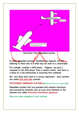
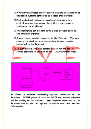
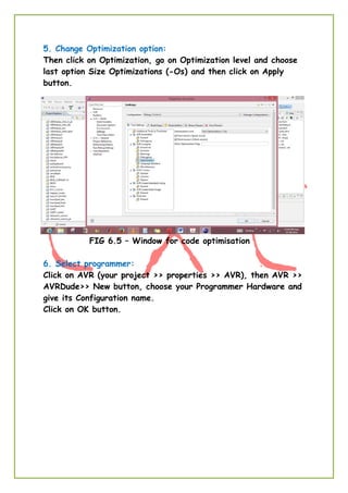
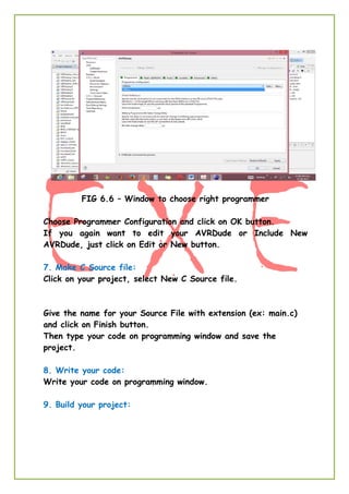
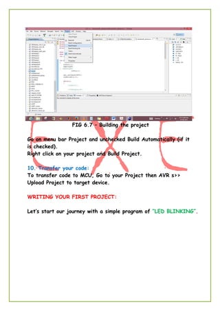
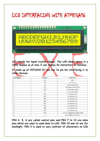
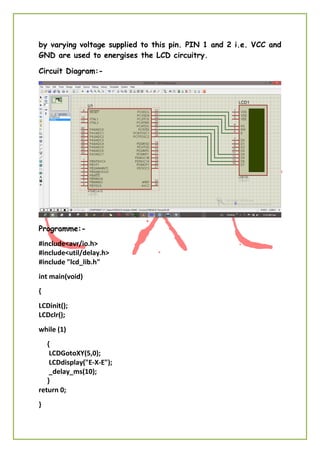
Enabling xtreme Engineering
RAJESH ROSHAN
DEPT.OF E.C.E.
NIT PATNA- 800006
rajesh.ece.nitp@gmail.com
E x E
Training
Program 2014
INTRODUCTION
TO EMBEDDED SYSTEM
INTRODUCTION
EMBEDDED SYSTEM
ey everyone! Welcome to the world of embedded systems.
I Rajesh Roshan will be guiding you all through this
journey of “Embedded Systems” and will try to make it
one of the most interesting and interactive course of E-x-E.
And for that I will need your help …… I mean to say your
interest and attention.
So, what is Embedded System?
“Embedded System can be defined as integration of Software
and Hardware to perform a specific task.”
This can be considered as the simplest and most accurate
definition of EMBEDDED SYSTEM.
Other definitions which I don’t consider worth remembering
are……
“A specialized computer system that is part of a larger system
or machine. Typically, an embedded system is housed on a single
microprocessor board with the programs stored in ROM.”
Or
“An embedded system is a computer system designed for specific
control functions within a larger system. Often with real-time
computing constraints. It is embedded as part of a complete
device often including hardware and mechanical parts”
But of course you may consider it for DEALING purposes.
So, almost most of the household comfort items are example of
Embedded System for example TV, Fridge, Washing Machines,
CFLs, your Trimmers …… of course and many more. You will find
them everywhere, that why THIS COURSE is so important these
days.
H
Now let’s see in how many ways we can categories EMBEDDED
SYSTEM.
1. Stand Alone Embedded System
2. Real – Time Embedded System
3. Mobile Embedded System
4. Network Embedded System
Now let’s see all of these in details.
STAND ALONE EMBEDDED SYSTEM:-
As the name implies, stand-alone systems work in stand- alone
mode. They take inputs, process them and produce the desired
output.
The input can be electrical signals from transducers or commands
from a human being such as the pressing of a button.
The output can be electrical signals to drive another system, an
LED display or LCD display for displaying of information to the
users.
Embedded systems used in process control, automobiles,
consumer electronic items etc. fall into this category.
REAL-TIME EMEDEDDED SYSTEM:-
Embedded systems in which some specific work has to be done in
a specific time period are called real-time systems.
For example, consider a system that has to open a valve within
30 milliseconds when the humidity crosses a particular threshold.
If the valve is not opened within 30 milliseconds, a catastrophe
may occur.
Such systems with strict deadlines are called hard real-time
systems.
Hard Real-Time Embedded System
In some embedded systems, deadlines are imposed, but not
adhering to them once in a while may not lead to a catastrophe.
For example, consider a DVD player. Suppose, you give a
command to the DVD player from a remote control, and there is
a delay of a few milliseconds in executing that command.
But, this delay won’t lead to a serious implication. Such systems
are called soft real-time systems.
NETWORKED EMBEDDED SYSTEMS (Networked Information Appliances):-
Embedded systems that are provided with network interfaces
and accessed by networks such as Local Area Network or the
Internet are called networked information appliances.
Here are some examples of such systems
 A networked process control system consists of a number of
embedded systems connected as a local area network.
 Each embedded system can send real-time data to a
central location from where the entire process control
system can be monitored.
 The monitoring can be done using a web browser such as
the Internet Explorer.
 A web camera can be connected to the Internet. The web
camera can send pictures in real-time to any computer
connected to the Internet.
 In such a case, the web camera has to run the HTTP
server software in addition to the TCP/IP protocol stack.
It shows a weather monitoring system connected to the
Internet. TCP/IP protocol suite and HTTP web server software
will be running on this system. Any computer connected to the
Internet can access this system to obtain real-time weather
information.
MOBILE EMBEDDED SYSTEMS (Mobile Devices):-
Mobile devices such as mobile phones, Personal Digital Assistants
(PDAs), smart phones etc. are a special category of embedded
systems. Though the PDAs do many general purpose tasks, they
need to be designed just like the ‘conventional’ embedded
systems.
So, we are done with the basic intro of embedded system
and its classification.
Now let’s see what are the basic Components and Skills that we
need to learn and practice Embedded System.
Components:-
1. Software Components
2. Hardware Components
Skills:-
1. Analysing Skill.
2. Coding Skill.
So let’s assume that you all are having these skills and can easily
analyse and code these problems.
So what you are having the desired skills … you need some editor
to write your codes such as notepad or something…. But can
those codes be directly feed to the machine you are hoping to
design?
NO.
For this purpose i.e. to make your code compatible for machines
you need to convert that into hex code (machine code) we need a
compiler like BORLAND or GCC.
Now you have codes (hex codes) that can directly be feed into
your systems. But the question is how? Can you transfer these
codes to your MCU using regular wires? To serve this purpose we
need a programmer (software) like (SinaProg, PonyProg,
AVRDUDE) and a special connecter like (9-pin SERIAL, 25-pin
PARALLEL or 4-pin USB).
Great, now you can analyse a problem, write the solution (code),
and transfer it to the machine you are designing. But you ever
thought where these codes will be stored and how it will get
executed. For this purpose you need some microprocessor or
microcontroller like 8051, ATmega16 etc.
So let’s see what sort of components we will be using…..
Coding Language - Embedded C
Editor – Eclipse
Compiler – AVR GCC
Programmer – AVRDUDE
Connector – 4-pin USB (USBtiny)
Microcontroller – ATmega16
If you all are equipped with these entire things then you are
just one step behind the starting your expedition of Embedded
World.
CREATING FIRST PROJECT ON ECLLIPSE:
1. First install WINAVR and JAVA Runtime Environment:
Install WINAVR and JAVA Runtime Environment.
2. Run eclipse:
There is no need to install eclipse in your computer. Just double
click on eclipse.exe setup.
3. Make a new project:
Right click on Project Explorer and select a new C project.
FIG: User Interface of Eclipse
Type your Project name (for example: ExE_lab1) and click on
Next>>Next button. Set your MCU Type and MCU Frequency
(for example MCU: Atmega16 and its frequency: 4000000).
FIG: creating a new project in eclipse
FIG: Setting the properties of target hardware
4. Enable HEX files generation:
Again go to Project Explorer and right click on your project, and
then go for its properties. Double click on C/C++Build then click
on Settings. Enable option Generate HEX file for Flash memory.
FIG: Enabling hex file generation
5. Change Optimization option:
Then click on Optimization, go on Optimization level and choose
last option Size Optimizations (-Os) and then click on Apply
button.
FIG 6.5 – Window for code optimisation
6. Select programmer:
Click on AVR (your project >> properties >> AVR), then AVR >>
AVRDude>> New button, choose your Programmer Hardware and
give its Configuration name.
Click on OK button.
FIG 6.6 – Window to choose right programmer
Choose Programmer Configuration and click on OK button.
If you again want to edit your AVRDude or Include New
AVRDude, just click on Edit or New button.
7. Make C Source file:
Click on your project, select New C Source file.
Give the name for your Source File with extension (ex: main.c)
and click on Finish button.
Then type your code on programming window and save the
project.
8. Write your code:
Write your code on programming window.
9. Build your project:
FIG 6.7 – Building the project
Go on menu bar Project and unchecked Build Automatically (if it
is checked).
Right click on your project and Build Project.
10. Transfer your code:
To transfer code to MCU, Go to your Project then AVR s>>
Upload Project to target device.
WRITING YOUR FIRST PROJECT:
Let’s start our journey with a simple program of “LED BLINKING”.
Here eight LEDs are connected to 8 pins of PORT A and are
made to glow one after another.
Some Basic Concepts of Embedded System
Microprocessors:-Integrated circuit semiconductor chip that
performs the bulk of the processing and controls the parts of a
system or simply which looks after all arithmetic and logical
operation of a system. But in short most basic and accurate
definition would be
“Microprocessor is a C.P.U. on chip.”
Some of the most common microprocessors that we come
across our B.Tech carrier are Intel 8085, Intel 8086, and
Motorola’s 680x0 family.
Microcontrollers:-Integrated circuit semiconductor chip that
performs the bulk of the processing, stores data and do contain
ports to connect controls the peripheral devices of a system. Or,
simply it can be defined as
“Computer on chip”
It can be added that microcontrollers contains RAM, ROM, I/O
PORTs, timers in addition to those microprocessors.
Intel’s 8051 is one of most commonly used one but other
famous MCUs are Atmel’s Atmega Series microcontrollers, PIC,
ARM etc.
And when it comes to Embedded Systems Microcontrollers are
preferred over the Microprocessors as MCUs are small, concise
and gives higher power efficiency. And Embedded Systems are
always meant to be concise and more power efficient.
And as already been told that here the MCU we will be using is
Atmega16 which is 8-bit AVR Microcontroller with 16K Bytes
In-System Programmable Flash So, let’s see some of the
properties of Atmega16.
Features
• High-performance, Low-power AVR® 8-bit Microcontroller
• Advanced RISC Architecture
– 131 Powerful Instructions – Most Single-clock Cycle Execution
– 32 x 8 General Purpose Working Registers
– Fully Static Operation
– Up to 16 MIPS Throughput at 16 MHz
– On-chip 2-cycle Multiplier
• High Endurance Non-volatile Memory segments
– 16K Bytes of In-System Self-programmable Flash program memory
– 512 Bytes EEPROM
– 1K Byte Internal SRAM
– Write/Erase Cycles: 10,000 Flash/100,000 EEPROM
– Data retention: 20 years at 85°C/100 years at 25°C
– Optional Boot Code Section with Independent Lock Bits In-System Programming by On-chip
Boot Program True Read-While-Write Operation
– Programming Lock for Software Security
• JTAG (IEEE std. 1149.1 Compliant) Interface
– Boundary-scan Capabilities According to the JTAG Standard
– Extensive On-chip Debug Support
– Programming of Flash, EEPROM, Fuses, and Lock Bits through the JTAG Interface
• Peripheral Features
– Two 8-bit Timer/Counters with Separate Prescalers and Compare Modes
– One 16-bit Timer/Counter with Separate Prescaler, Compare Mode, and Capture Mode
– Real Time Counter with Separate Oscillator
– Four PWM Channels
– 8-channel, 10-bit ADC
– Byte-oriented Two-wire Serial Interface
– Programmable Serial USART
– Master/Slave SPI Serial Interface
– Programmable Watchdog Timer with Separate On-chip Oscillator
– On-chip Analog Comparator
• Special Microcontroller Features
– Power-on Reset and Programmable Brown-out Detection
– Internal Calibrated RC Oscillator
– External and Internal Interrupt Sources
• I/O and Packages
– 32 Programmable I/O Lines
– 40-pin PDIP, 44-lead TQFP, and 44-pad QFN/MLF
• Operating Voltages
– 2.7 - 5.5V for ATmega16L
– 4.5 - 5.5V for ATmega16
• Speed Grades
– 0 - 8 MHz for ATmega16L
– 0 - 16 MHz for ATmega16
• Power Consumption @ 1 MHz, 3V, and 25°C for ATmega16L
– Active: 1.1 mA
– Idle Mode: 0.35 mA
– Power-down Mode: < 1 μA
Pin Configuration of Atmega16 is shown below.
In general all the four POTRs of it can be used as I/0 port but
they carry some unique features such as,
PORTA = Contains ADC, so generally used to take input.
PORTB = Programming purpose (i.e. transferring codes to chip)
PORTD = Communication (Contains Rx and Tx)
LCD INTERFACING WITH ATMEGA16
LCD stands for liquid crystal display. The LCD shown above is a
16X2 display so at max it can display 32 characters at instance.
It made up of HITACHI IC and has 16 pin for interfacing it to
other devices.
PIN 4, 5, 6 are called control pins and PIN 7 to 14 are data
pins which are used to send data to LCD. PIN 15 and 16 are for
backlight. PIN 3 is used to vary contrast of characters on LCD
by varying voltage supplied to this pin. PIN 1 and 2 i.e. VCC and
GND are used to energises the LCD circuitry.
Circuit Diagram:-
Programme:-
#include<avr/io.h>
#include<util/delay.h>
#include "lcd_lib.h"
int main(void)
{
LCDinit();
LCDclr();
while (1)
{
LCDGotoXY(5,0);
LCDdisplay("E-X-E");
_delay_ms(10);
}
return 0;
}

Basics of Embedded System

  • 1.
    Enabling xtreme Engineering RAJESHROSHAN DEPT.OF E.C.E. NIT PATNA- 800006 rajesh.ece.nitp@gmail.com E x E Training Program 2014 INTRODUCTION TO EMBEDDED SYSTEM
  • 2.
    INTRODUCTION EMBEDDED SYSTEM ey everyone!Welcome to the world of embedded systems. I Rajesh Roshan will be guiding you all through this journey of “Embedded Systems” and will try to make it one of the most interesting and interactive course of E-x-E. And for that I will need your help …… I mean to say your interest and attention. So, what is Embedded System? “Embedded System can be defined as integration of Software and Hardware to perform a specific task.” This can be considered as the simplest and most accurate definition of EMBEDDED SYSTEM. Other definitions which I don’t consider worth remembering are…… “A specialized computer system that is part of a larger system or machine. Typically, an embedded system is housed on a single microprocessor board with the programs stored in ROM.” Or “An embedded system is a computer system designed for specific control functions within a larger system. Often with real-time computing constraints. It is embedded as part of a complete device often including hardware and mechanical parts” But of course you may consider it for DEALING purposes. So, almost most of the household comfort items are example of Embedded System for example TV, Fridge, Washing Machines, CFLs, your Trimmers …… of course and many more. You will find them everywhere, that why THIS COURSE is so important these days. H
  • 3.
    Now let’s seein how many ways we can categories EMBEDDED SYSTEM. 1. Stand Alone Embedded System 2. Real – Time Embedded System 3. Mobile Embedded System 4. Network Embedded System Now let’s see all of these in details. STAND ALONE EMBEDDED SYSTEM:- As the name implies, stand-alone systems work in stand- alone mode. They take inputs, process them and produce the desired output. The input can be electrical signals from transducers or commands from a human being such as the pressing of a button. The output can be electrical signals to drive another system, an LED display or LCD display for displaying of information to the users. Embedded systems used in process control, automobiles, consumer electronic items etc. fall into this category. REAL-TIME EMEDEDDED SYSTEM:- Embedded systems in which some specific work has to be done in a specific time period are called real-time systems. For example, consider a system that has to open a valve within 30 milliseconds when the humidity crosses a particular threshold. If the valve is not opened within 30 milliseconds, a catastrophe may occur. Such systems with strict deadlines are called hard real-time systems.
  • 4.
    Hard Real-Time EmbeddedSystem In some embedded systems, deadlines are imposed, but not adhering to them once in a while may not lead to a catastrophe. For example, consider a DVD player. Suppose, you give a command to the DVD player from a remote control, and there is a delay of a few milliseconds in executing that command. But, this delay won’t lead to a serious implication. Such systems are called soft real-time systems. NETWORKED EMBEDDED SYSTEMS (Networked Information Appliances):- Embedded systems that are provided with network interfaces and accessed by networks such as Local Area Network or the Internet are called networked information appliances. Here are some examples of such systems
  • 5.
     A networkedprocess control system consists of a number of embedded systems connected as a local area network.  Each embedded system can send real-time data to a central location from where the entire process control system can be monitored.  The monitoring can be done using a web browser such as the Internet Explorer.  A web camera can be connected to the Internet. The web camera can send pictures in real-time to any computer connected to the Internet.  In such a case, the web camera has to run the HTTP server software in addition to the TCP/IP protocol stack. It shows a weather monitoring system connected to the Internet. TCP/IP protocol suite and HTTP web server software will be running on this system. Any computer connected to the Internet can access this system to obtain real-time weather information.
  • 6.
    MOBILE EMBEDDED SYSTEMS(Mobile Devices):- Mobile devices such as mobile phones, Personal Digital Assistants (PDAs), smart phones etc. are a special category of embedded systems. Though the PDAs do many general purpose tasks, they need to be designed just like the ‘conventional’ embedded systems. So, we are done with the basic intro of embedded system and its classification. Now let’s see what are the basic Components and Skills that we need to learn and practice Embedded System. Components:- 1. Software Components 2. Hardware Components Skills:- 1. Analysing Skill. 2. Coding Skill. So let’s assume that you all are having these skills and can easily analyse and code these problems. So what you are having the desired skills … you need some editor to write your codes such as notepad or something…. But can those codes be directly feed to the machine you are hoping to design? NO. For this purpose i.e. to make your code compatible for machines you need to convert that into hex code (machine code) we need a compiler like BORLAND or GCC. Now you have codes (hex codes) that can directly be feed into your systems. But the question is how? Can you transfer these
  • 7.
    codes to yourMCU using regular wires? To serve this purpose we need a programmer (software) like (SinaProg, PonyProg, AVRDUDE) and a special connecter like (9-pin SERIAL, 25-pin PARALLEL or 4-pin USB). Great, now you can analyse a problem, write the solution (code), and transfer it to the machine you are designing. But you ever thought where these codes will be stored and how it will get executed. For this purpose you need some microprocessor or microcontroller like 8051, ATmega16 etc. So let’s see what sort of components we will be using….. Coding Language - Embedded C Editor – Eclipse Compiler – AVR GCC Programmer – AVRDUDE Connector – 4-pin USB (USBtiny) Microcontroller – ATmega16 If you all are equipped with these entire things then you are just one step behind the starting your expedition of Embedded World. CREATING FIRST PROJECT ON ECLLIPSE: 1. First install WINAVR and JAVA Runtime Environment: Install WINAVR and JAVA Runtime Environment. 2. Run eclipse: There is no need to install eclipse in your computer. Just double click on eclipse.exe setup. 3. Make a new project: Right click on Project Explorer and select a new C project.
  • 8.
    FIG: User Interfaceof Eclipse Type your Project name (for example: ExE_lab1) and click on Next>>Next button. Set your MCU Type and MCU Frequency (for example MCU: Atmega16 and its frequency: 4000000). FIG: creating a new project in eclipse
  • 9.
    FIG: Setting theproperties of target hardware 4. Enable HEX files generation: Again go to Project Explorer and right click on your project, and then go for its properties. Double click on C/C++Build then click on Settings. Enable option Generate HEX file for Flash memory. FIG: Enabling hex file generation
  • 10.
    5. Change Optimizationoption: Then click on Optimization, go on Optimization level and choose last option Size Optimizations (-Os) and then click on Apply button. FIG 6.5 – Window for code optimisation 6. Select programmer: Click on AVR (your project >> properties >> AVR), then AVR >> AVRDude>> New button, choose your Programmer Hardware and give its Configuration name. Click on OK button.
  • 11.
    FIG 6.6 –Window to choose right programmer Choose Programmer Configuration and click on OK button. If you again want to edit your AVRDude or Include New AVRDude, just click on Edit or New button. 7. Make C Source file: Click on your project, select New C Source file. Give the name for your Source File with extension (ex: main.c) and click on Finish button. Then type your code on programming window and save the project. 8. Write your code: Write your code on programming window. 9. Build your project:
  • 12.
    FIG 6.7 –Building the project Go on menu bar Project and unchecked Build Automatically (if it is checked). Right click on your project and Build Project. 10. Transfer your code: To transfer code to MCU, Go to your Project then AVR s>> Upload Project to target device. WRITING YOUR FIRST PROJECT: Let’s start our journey with a simple program of “LED BLINKING”.
  • 13.
    Here eight LEDsare connected to 8 pins of PORT A and are made to glow one after another.
  • 14.
    Some Basic Conceptsof Embedded System Microprocessors:-Integrated circuit semiconductor chip that performs the bulk of the processing and controls the parts of a system or simply which looks after all arithmetic and logical operation of a system. But in short most basic and accurate definition would be “Microprocessor is a C.P.U. on chip.” Some of the most common microprocessors that we come across our B.Tech carrier are Intel 8085, Intel 8086, and Motorola’s 680x0 family. Microcontrollers:-Integrated circuit semiconductor chip that performs the bulk of the processing, stores data and do contain ports to connect controls the peripheral devices of a system. Or, simply it can be defined as “Computer on chip” It can be added that microcontrollers contains RAM, ROM, I/O PORTs, timers in addition to those microprocessors. Intel’s 8051 is one of most commonly used one but other famous MCUs are Atmel’s Atmega Series microcontrollers, PIC, ARM etc. And when it comes to Embedded Systems Microcontrollers are preferred over the Microprocessors as MCUs are small, concise and gives higher power efficiency. And Embedded Systems are always meant to be concise and more power efficient. And as already been told that here the MCU we will be using is Atmega16 which is 8-bit AVR Microcontroller with 16K Bytes In-System Programmable Flash So, let’s see some of the properties of Atmega16.
  • 15.
    Features • High-performance, Low-powerAVR® 8-bit Microcontroller • Advanced RISC Architecture – 131 Powerful Instructions – Most Single-clock Cycle Execution – 32 x 8 General Purpose Working Registers – Fully Static Operation – Up to 16 MIPS Throughput at 16 MHz – On-chip 2-cycle Multiplier • High Endurance Non-volatile Memory segments – 16K Bytes of In-System Self-programmable Flash program memory – 512 Bytes EEPROM – 1K Byte Internal SRAM – Write/Erase Cycles: 10,000 Flash/100,000 EEPROM – Data retention: 20 years at 85°C/100 years at 25°C – Optional Boot Code Section with Independent Lock Bits In-System Programming by On-chip Boot Program True Read-While-Write Operation – Programming Lock for Software Security • JTAG (IEEE std. 1149.1 Compliant) Interface – Boundary-scan Capabilities According to the JTAG Standard – Extensive On-chip Debug Support – Programming of Flash, EEPROM, Fuses, and Lock Bits through the JTAG Interface • Peripheral Features – Two 8-bit Timer/Counters with Separate Prescalers and Compare Modes – One 16-bit Timer/Counter with Separate Prescaler, Compare Mode, and Capture Mode – Real Time Counter with Separate Oscillator – Four PWM Channels – 8-channel, 10-bit ADC – Byte-oriented Two-wire Serial Interface – Programmable Serial USART – Master/Slave SPI Serial Interface – Programmable Watchdog Timer with Separate On-chip Oscillator – On-chip Analog Comparator • Special Microcontroller Features – Power-on Reset and Programmable Brown-out Detection – Internal Calibrated RC Oscillator – External and Internal Interrupt Sources • I/O and Packages – 32 Programmable I/O Lines – 40-pin PDIP, 44-lead TQFP, and 44-pad QFN/MLF • Operating Voltages – 2.7 - 5.5V for ATmega16L – 4.5 - 5.5V for ATmega16 • Speed Grades – 0 - 8 MHz for ATmega16L – 0 - 16 MHz for ATmega16 • Power Consumption @ 1 MHz, 3V, and 25°C for ATmega16L – Active: 1.1 mA – Idle Mode: 0.35 mA – Power-down Mode: < 1 μA
  • 16.
    Pin Configuration ofAtmega16 is shown below. In general all the four POTRs of it can be used as I/0 port but they carry some unique features such as, PORTA = Contains ADC, so generally used to take input. PORTB = Programming purpose (i.e. transferring codes to chip) PORTD = Communication (Contains Rx and Tx)
  • 17.
    LCD INTERFACING WITHATMEGA16 LCD stands for liquid crystal display. The LCD shown above is a 16X2 display so at max it can display 32 characters at instance. It made up of HITACHI IC and has 16 pin for interfacing it to other devices. PIN 4, 5, 6 are called control pins and PIN 7 to 14 are data pins which are used to send data to LCD. PIN 15 and 16 are for backlight. PIN 3 is used to vary contrast of characters on LCD
  • 18.
    by varying voltagesupplied to this pin. PIN 1 and 2 i.e. VCC and GND are used to energises the LCD circuitry. Circuit Diagram:- Programme:- #include<avr/io.h> #include<util/delay.h> #include "lcd_lib.h" int main(void) { LCDinit(); LCDclr(); while (1) { LCDGotoXY(5,0); LCDdisplay("E-X-E"); _delay_ms(10); } return 0; }