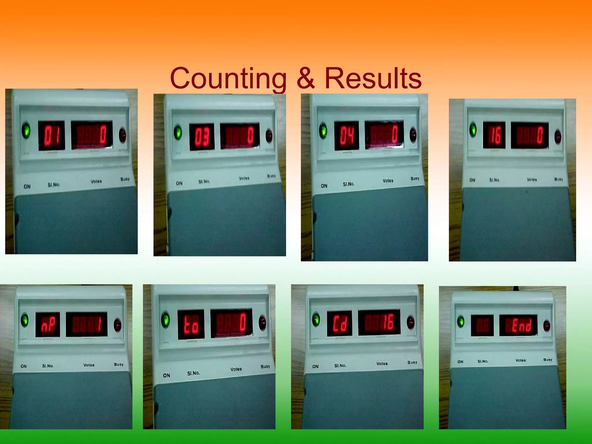
This document provides information about electronic voting machines (EVMs) used in India. It discusses how EVMs work, their components like the ballot unit and control unit, and the sequence of operations using the buttons on the control unit. Images show different parts of the EVM like the display screens and internal components. The document also briefly mentions awareness programs conducted to demonstrate EVMs and the process for counting votes cast using EVMs.
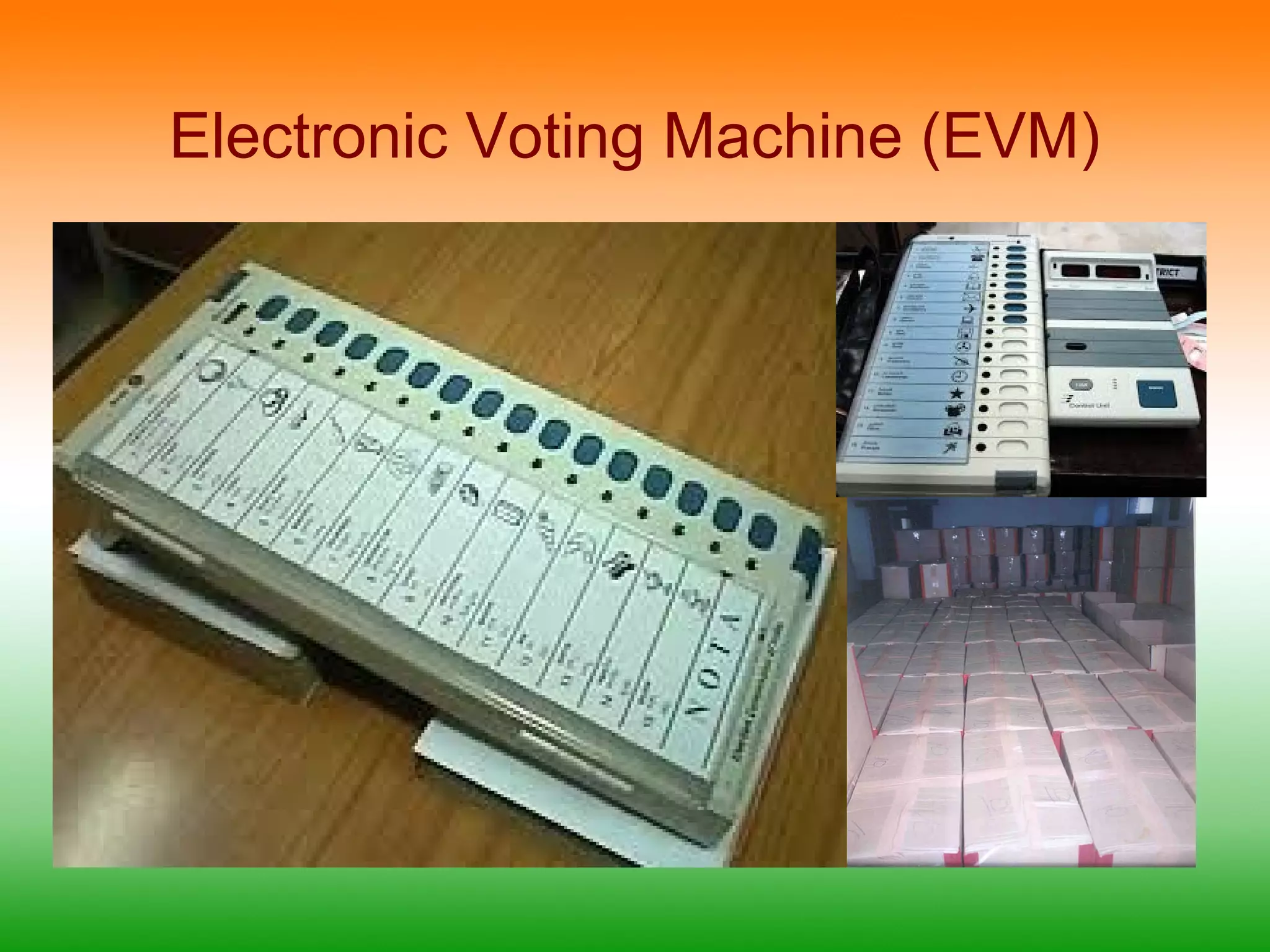
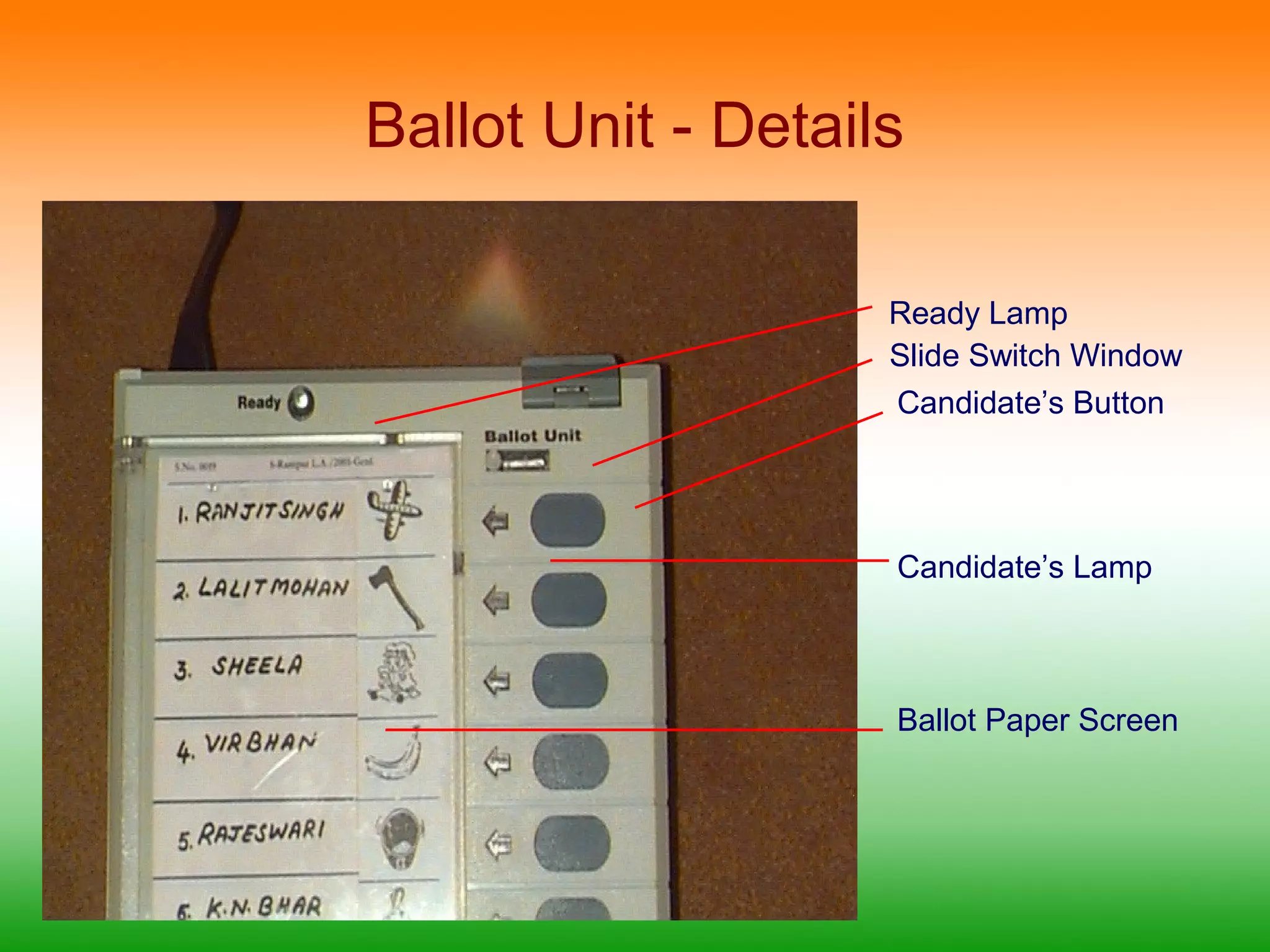
Ballot Unit -Details
Ready Lamp
Slide Switch Window
Candidate’s Button
Candidate’s Lamp
Ballot Paper Screen
12.
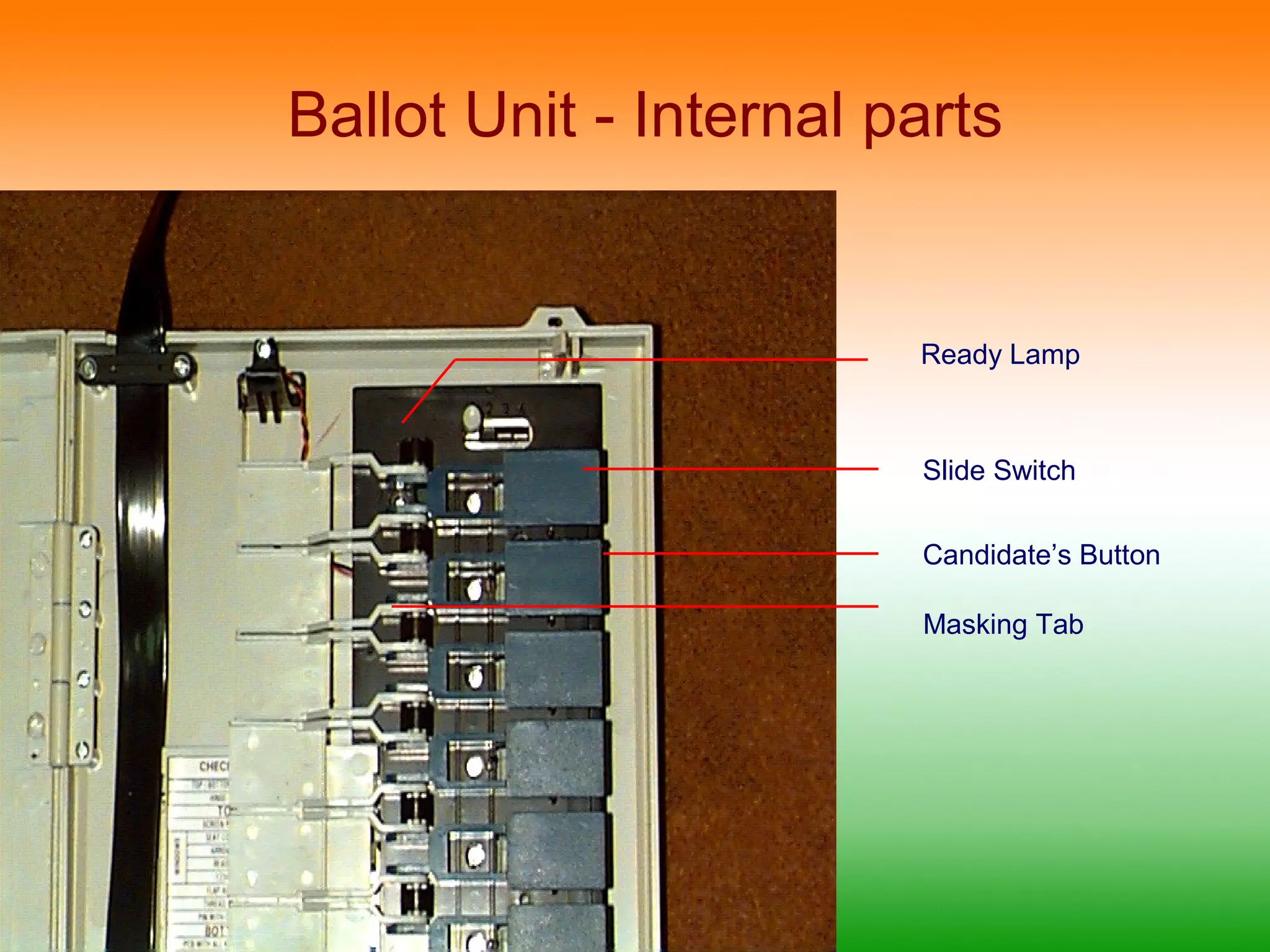
Ballot Unit -Internal parts
Ready Lamp
Slide Switch
Candidate’s Button
Masking Tab
13.
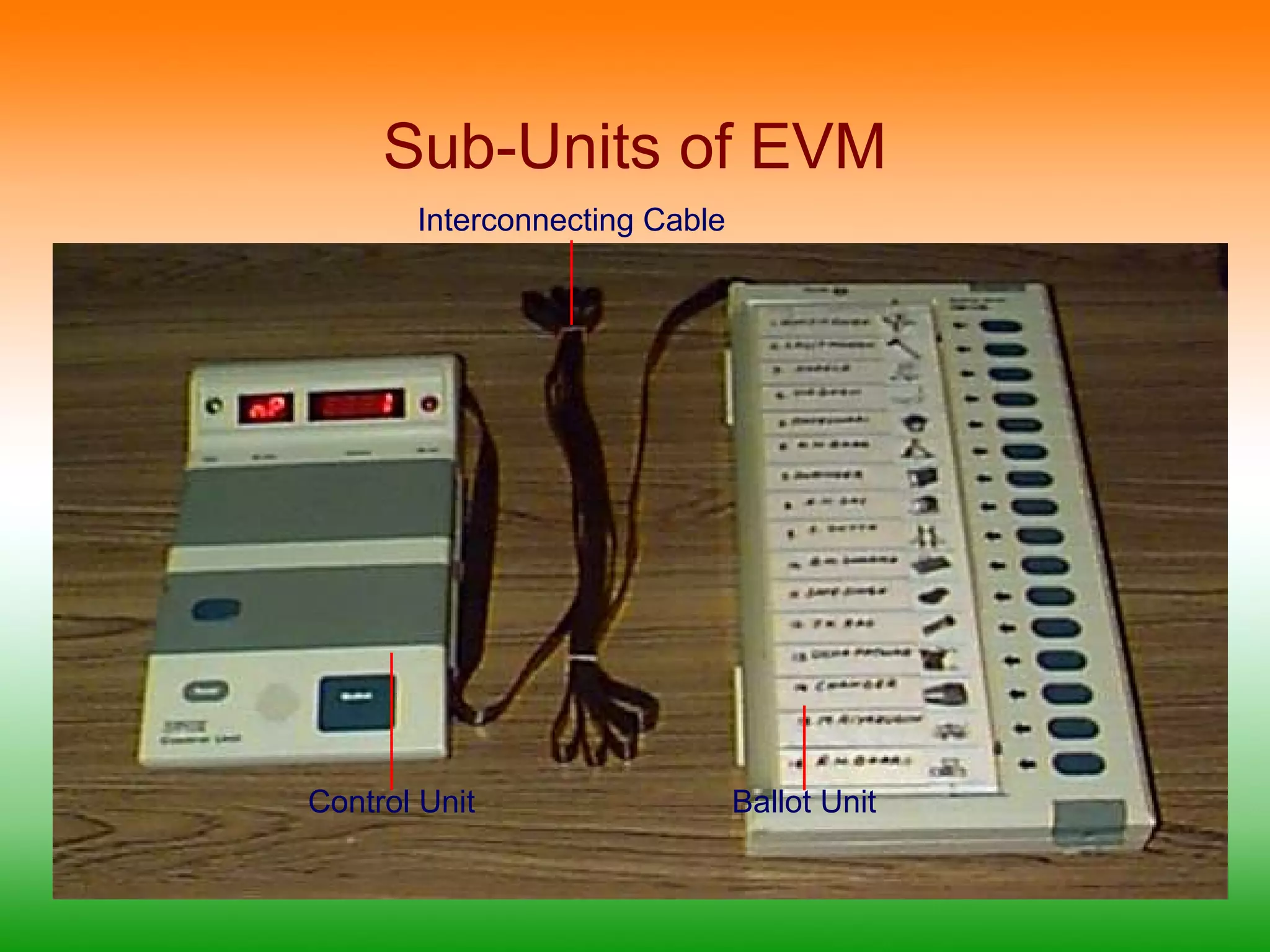
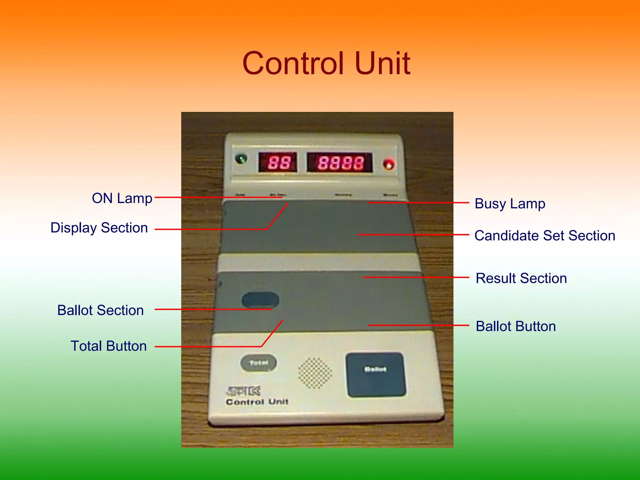
Control Unit
ONLamp Busy Lamp
Display Section Candidate Set Section
Result Section
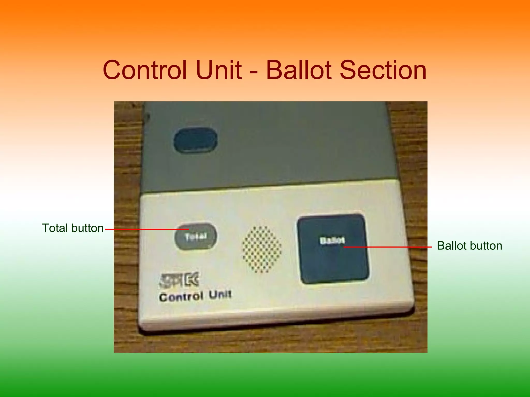
Ballot Section
Ballot Button
Total Button
14.
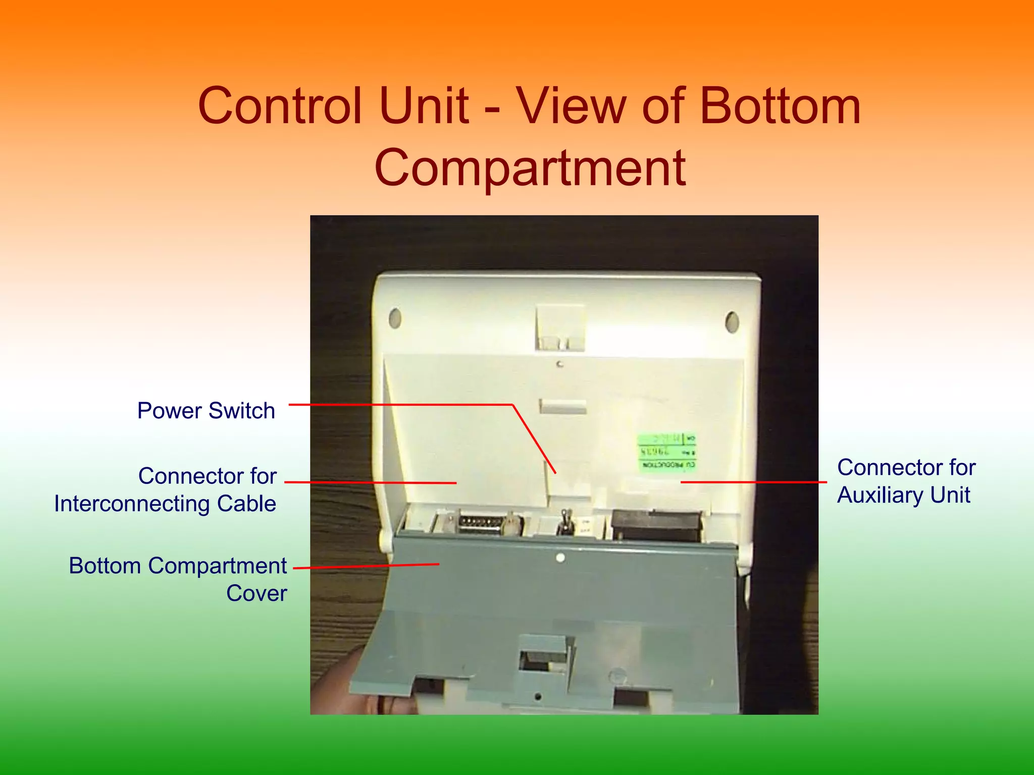
Control Unit -View of Bottom
Compartment
Power Switch
Connector for
Interconnecting Cable
Bottom Compartment
Cover
Connector for
Auxiliary Unit
15.
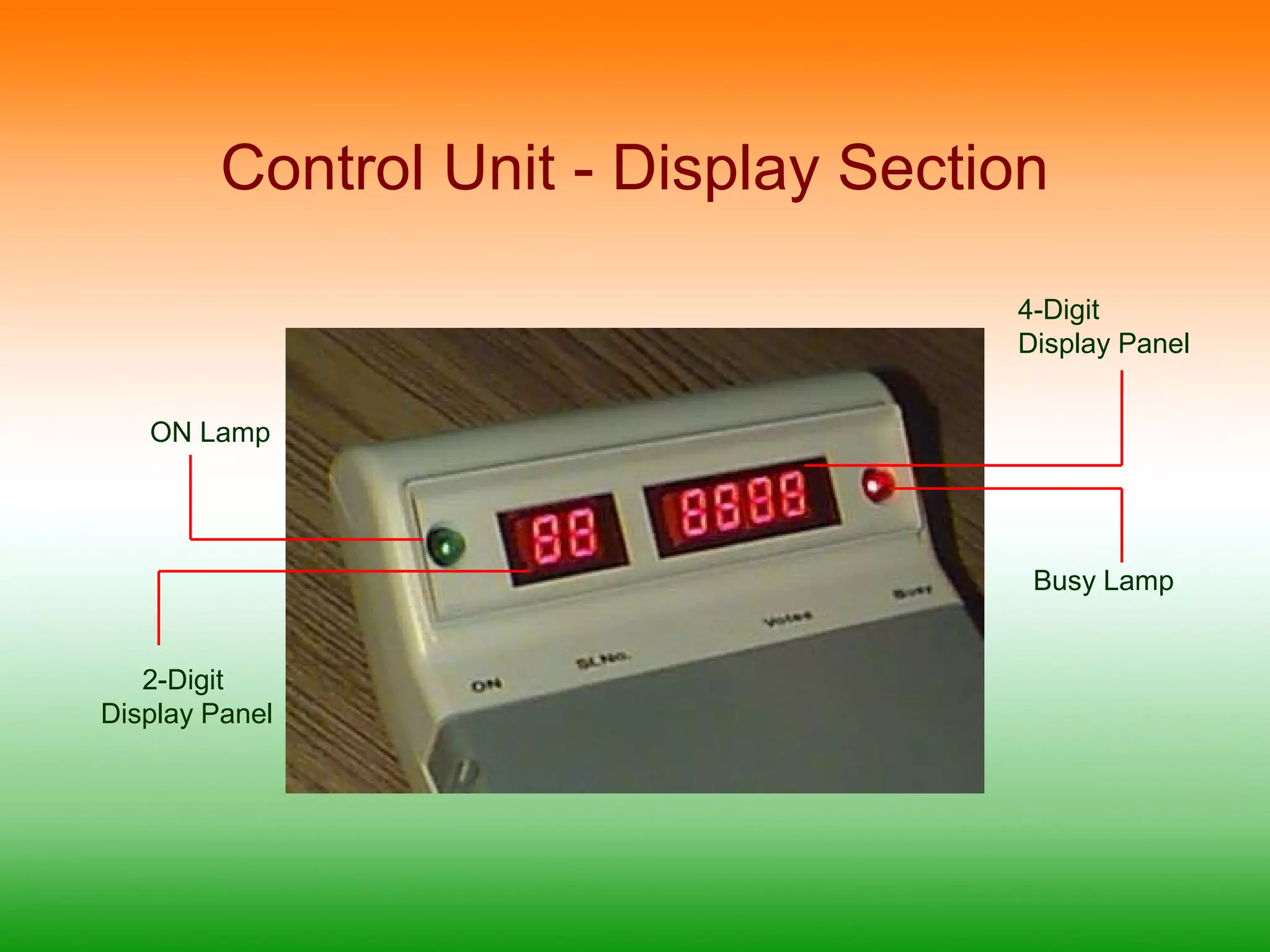
Control Unit -Display Section
4-Digit
Display Panel
ON Lamp
2-Digit
Display Panel
Busy Lamp
16.
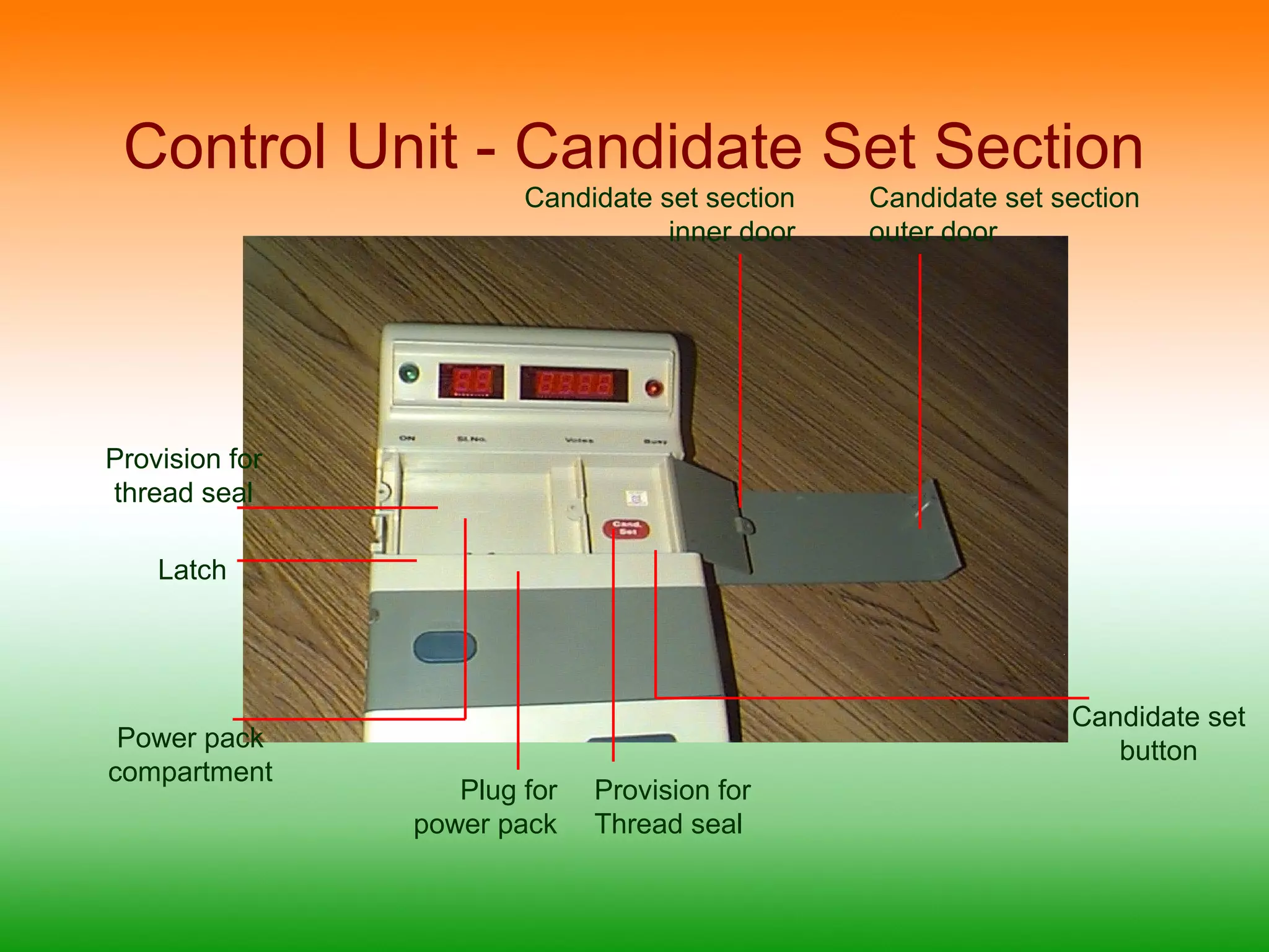
Control Unit -Candidate Set Section
Provision for
thread seal
Latch
Plug for
power pack
Candidate set
button
Candidate set section
inner door
Candidate set section
outer door
Provision for
Thread seal
Power pack
compartment
17.
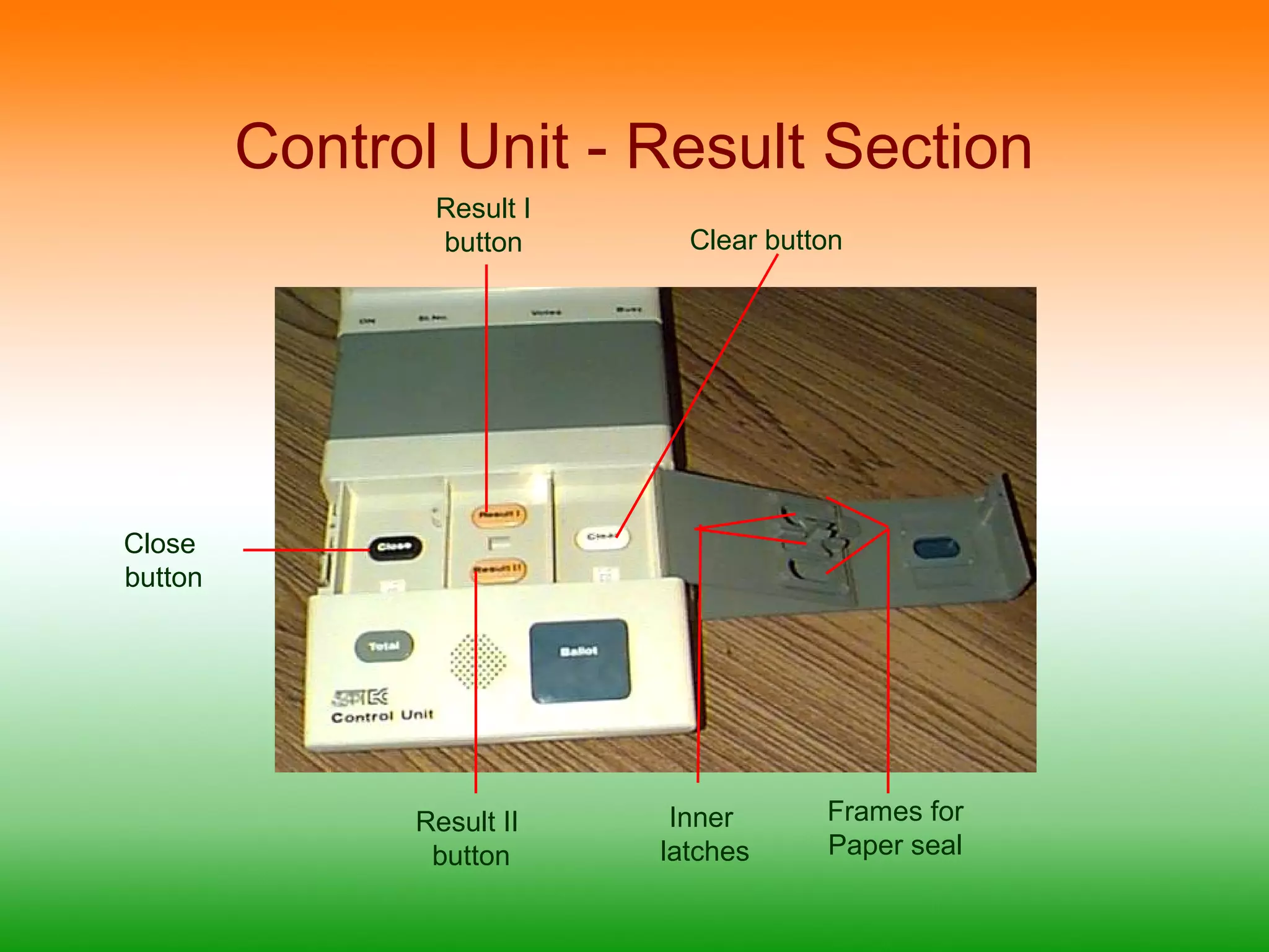
Control Unit -Result Section
Result I
button
Clear button
Inner
latches
Frames for
Paper seal
Result II
button
Close
button
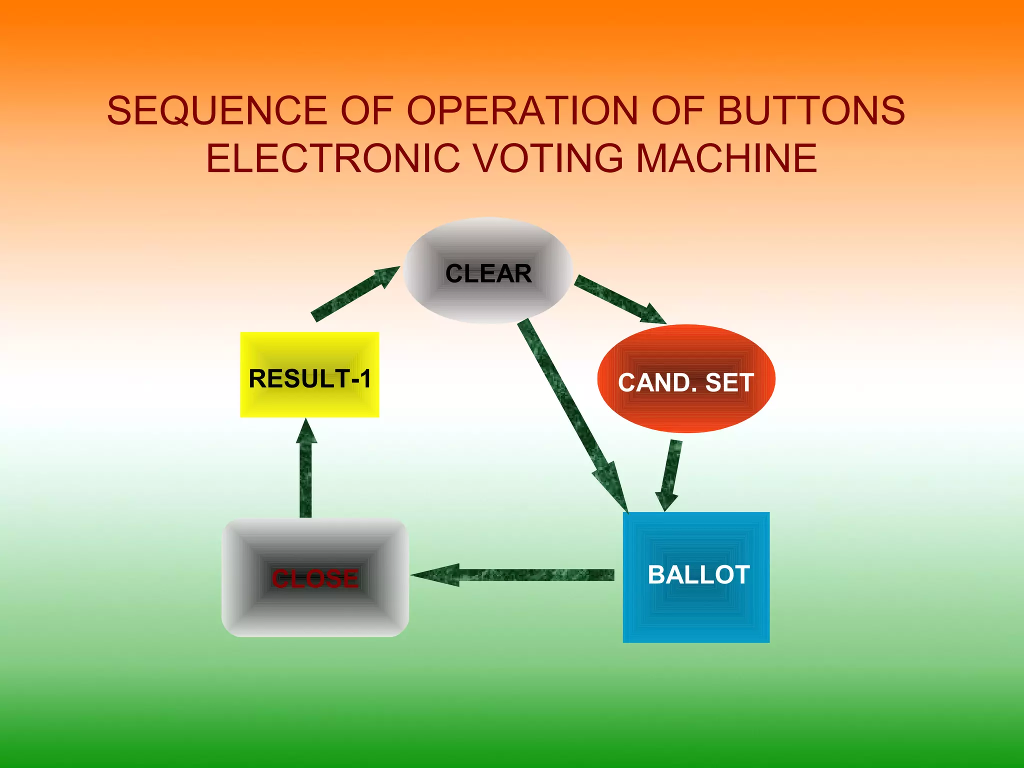
SEQUENCE OF OPERATIONOF BUTTONS
ELECTRONIC VOTING MACHINE
CAND. SET
CLEAR
BALLOT
RESULT-1
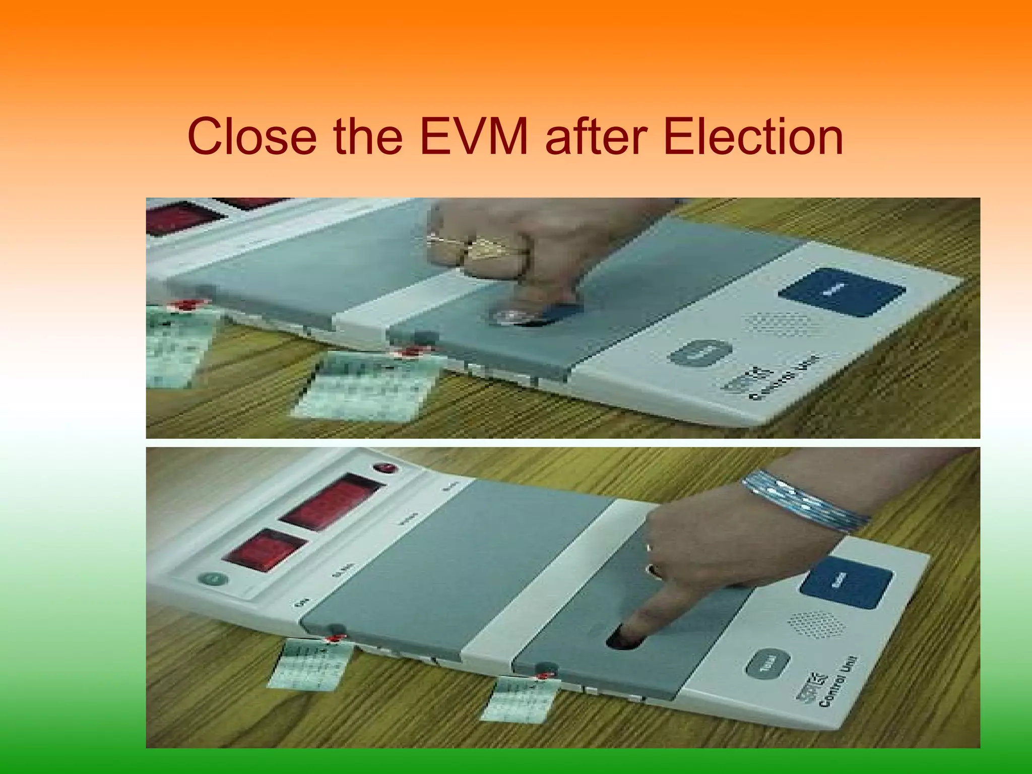
CLOSE
Editor's Notes
#12 The ready lamp glows when the unit is switched on
The slide switch is used to set the no of the unit, ie it is set to 1 if there are only 16 candidates and 1 for the first and 2 for the second if there are 17 to 32 candidates and so on
The candidate’s lamp glows indicating to the voter that his/her vote is cast in favor of that candidate
After the ballot paper is placed and aligned the screen is put in place and sealed
#13 Candidate button is the button which is pressed by the voter
Masking tab is used to mask the candidate buttons which are not in use; ie if there are only 8 candidates the remaining switches from 9 to 16 are masked and cannot be operated
#14 On lamp glows when the unit is powered on.
Busy Lamp glows when a ballot is released and a voter is in the process of voting. After the casting the lamp goes off with a beep thus indicating that the vote is cast
Total button may be pressed at any given time to know the total no of votes polled till then
Ballot button – pressing of this button releases a vote in the ballot unit and also results in the busy lamp glowing
#15 Power switch powers on / off the EVM
Connecter for connecting the Ballot unit with interconnecting cable
Auxiliary unit connector – to connect second ballot unit in case of two simultaneous polls
#17 Candidate set button: For setting the no of candidates in the poll. The Ballot unit and the control unit are connected and powered on. This button is pressed and the candidate button on the ballot unit corresponding to the last candidate is pressed.
#18 Close button:To close the poll at the end of the appointed period. Once this button is depressed no more votes can be cast on this machine
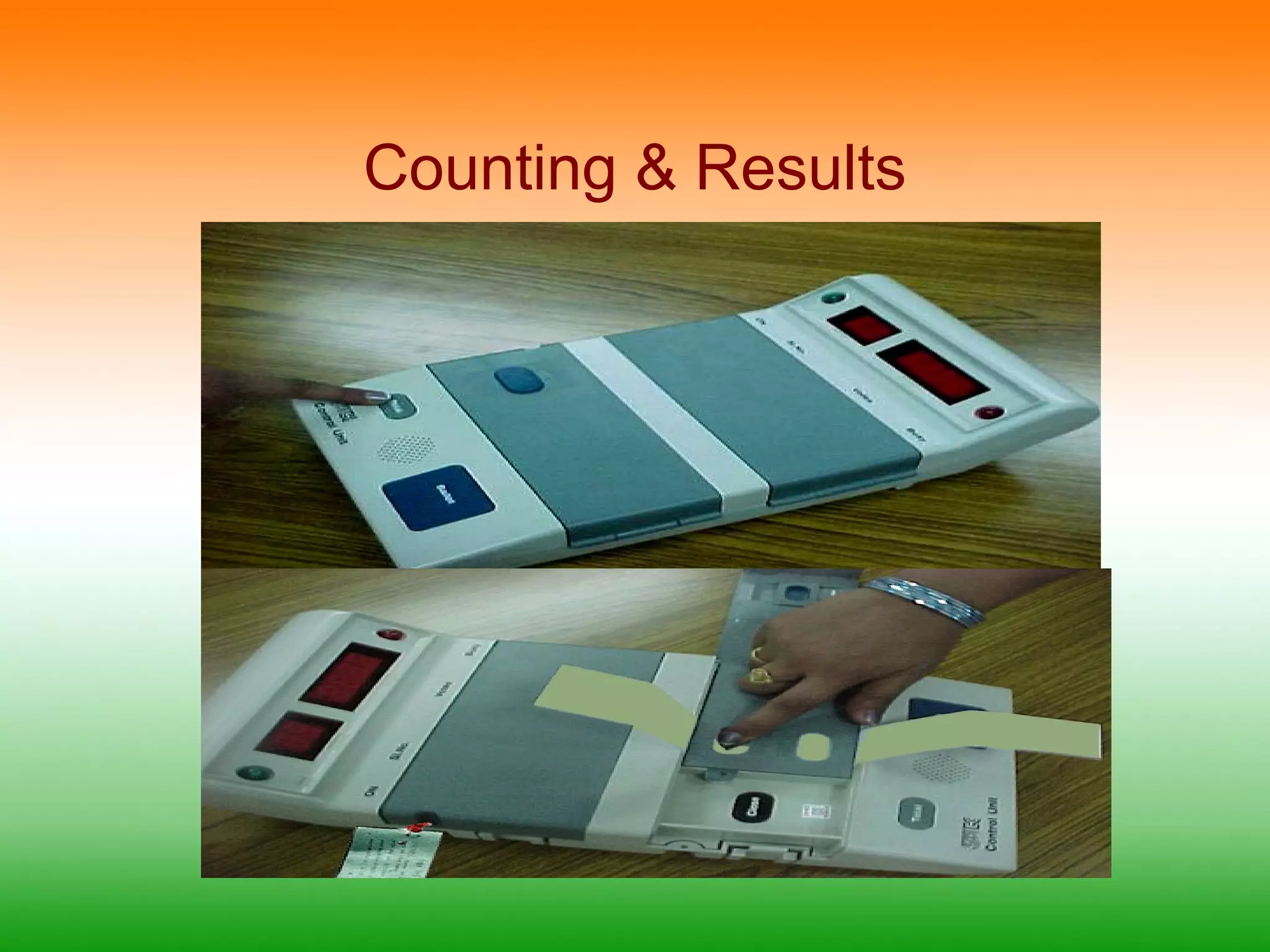
Result 1To view the results of poll 1
Result 2:To view the results of poll 2
Clear :Clears the data recorded in the voting machine – operable only after the results are viewed at least once