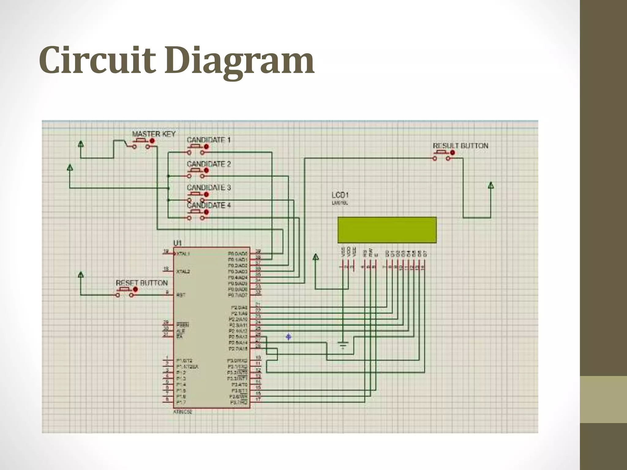
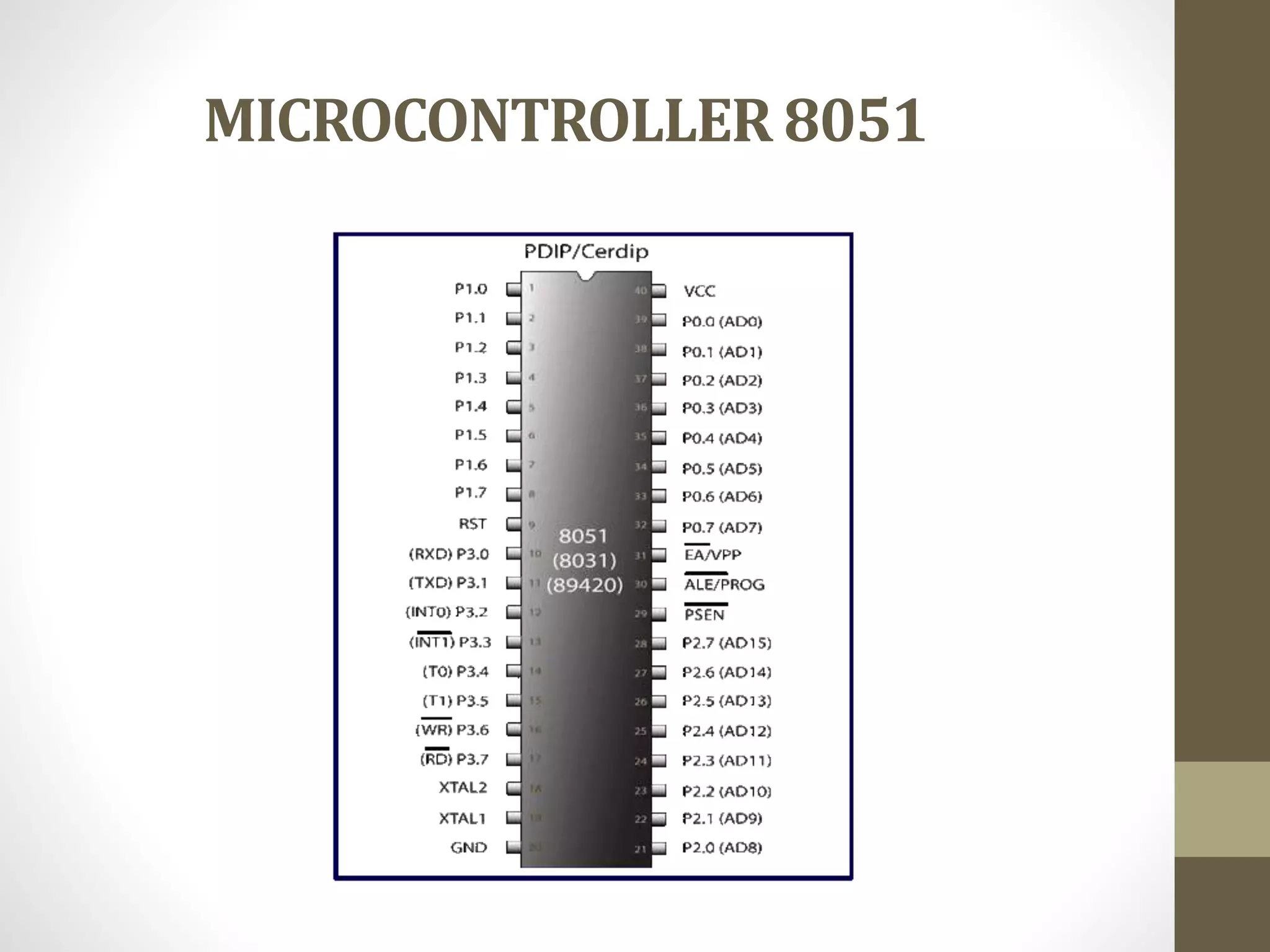
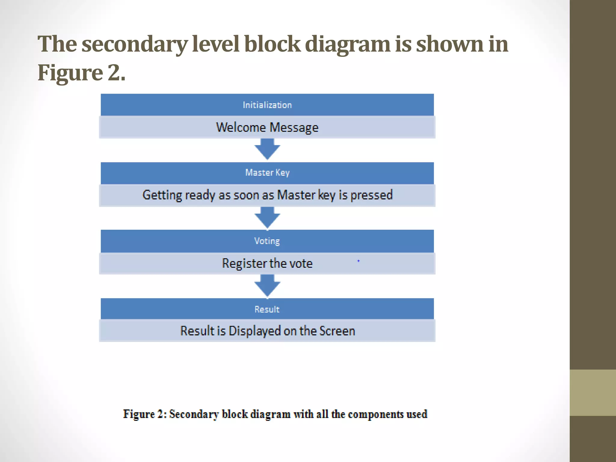
ELECTRONIC VOTING
MACHINE
Ashish Kumar Barai - 17BLC1139
Sagar Sharma - 17BLC1068
Sarthak Kathuria - 17BLC1152
Introduction
• An EVM consists of two units, control unit and balloting unit.
The two units are joined by a five-meter cable. Balloting unit
facilitates voting by voter via labelled buttons while control
unit controls the ballot units, stores voting counts and displays
the results on 7 segment LED displays. The controller used in
EVMs has its operating program etched permanently in silicon
at the time of manufacturing by the manufacturer. No one
(including the manufacturer) can change the program once
the controller is manufactured.
• An EVM can record a maximum of 3840 votes and can cater to
a maximum of 64 candidates. There is provision for 16
candidates in a single balloting unit and up to a maximum of 4
units can be connected in parallel. The conventional ballot
paper/box method of polling is used if the number of
candidates exceeds 64. It is not possible to vote more than
once by pressing the button again and again. As soon as a
particular button on the balloting unit is pressed, the vote is
recorded for that particular candidate and the machine gets
locked. Even if one presses that button further or any other
button, no further vote will be recorded. This way the EVMs
ensure the principle of "one person, one vote".
• The control unit is with the presiding officer or a polling officer
and the balloting Unit is placed inside the voting
compartment. The balloting unit presents the voter with blue
buttons (momentary switch) horizontally labelled with
corresponding party symbol and candidate names. The
Control Unit on the other hand provides the officer in-charge
with a "Ballot" marked button to proceed to the next voter,
instead of issuing a ballot paper to them. This activates the
ballot unit for a single vote from the next voter in queue.The
voter has to cast his vote by once pressing the blue button on
the balloting unit against the candidate and symbol of his
choice.
Circuit Diagram
MICROCONTROLLER 8051
FEATURES
• Secured code and algorithm
• Encrypted ballot module
• Use high end algorithm for calculating the winner
• Microcontroller used is low cost controller named as 8052
• Added Master Key far better Security.
The four main features of the basic block diagram
(given below) are
• The Microcontroller used – 8052
• The LCD for Display
• Master Key
• Voting Buttons
• Controller
Figure 1. GUI Controller
Figure 1 shows the GUI
controller for EVM.
Thesecondarylevelblockdiagramisshown in
Figure2.

Electronic voting machine.ppt

  • 1.
    ELECTRONIC VOTING MACHINE Ashish KumarBarai - 17BLC1139 Sagar Sharma - 17BLC1068 Sarthak Kathuria - 17BLC1152
  • 2.
    Introduction • An EVMconsists of two units, control unit and balloting unit. The two units are joined by a five-meter cable. Balloting unit facilitates voting by voter via labelled buttons while control unit controls the ballot units, stores voting counts and displays the results on 7 segment LED displays. The controller used in EVMs has its operating program etched permanently in silicon at the time of manufacturing by the manufacturer. No one (including the manufacturer) can change the program once the controller is manufactured.
  • 3.
    • An EVMcan record a maximum of 3840 votes and can cater to a maximum of 64 candidates. There is provision for 16 candidates in a single balloting unit and up to a maximum of 4 units can be connected in parallel. The conventional ballot paper/box method of polling is used if the number of candidates exceeds 64. It is not possible to vote more than once by pressing the button again and again. As soon as a particular button on the balloting unit is pressed, the vote is recorded for that particular candidate and the machine gets locked. Even if one presses that button further or any other button, no further vote will be recorded. This way the EVMs ensure the principle of "one person, one vote".
  • 4.
    • The controlunit is with the presiding officer or a polling officer and the balloting Unit is placed inside the voting compartment. The balloting unit presents the voter with blue buttons (momentary switch) horizontally labelled with corresponding party symbol and candidate names. The Control Unit on the other hand provides the officer in-charge with a "Ballot" marked button to proceed to the next voter, instead of issuing a ballot paper to them. This activates the ballot unit for a single vote from the next voter in queue.The voter has to cast his vote by once pressing the blue button on the balloting unit against the candidate and symbol of his choice.
  • 5.
  • 6.
  • 7.
    FEATURES • Secured codeand algorithm • Encrypted ballot module • Use high end algorithm for calculating the winner • Microcontroller used is low cost controller named as 8052 • Added Master Key far better Security.
  • 8.
    The four mainfeatures of the basic block diagram (given below) are • The Microcontroller used – 8052 • The LCD for Display • Master Key • Voting Buttons • Controller Figure 1. GUI Controller Figure 1 shows the GUI controller for EVM.
  • 9.