Downloaded 333 times


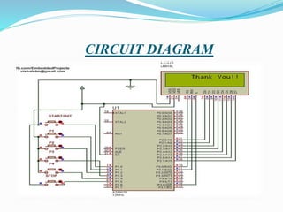
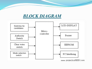


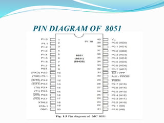


This document outlines the components, operation, and advantages/disadvantages of an electronic voting machine (EVM) system using an 8051 microcontroller. The key components of the EVM include an 8051 microcontroller, LCD display, control switches, and input keys. It operates by displaying voting modes and counting totals, with authority switches to control the voting process. Advantages include lower cost and time requirements compared to traditional systems, while disadvantages include needing external memory chips and a continuous power supply.


![Interfacing technique with 8085- ADC[0808]](https://cdn.slidesharecdn.com/ss_thumbnails/adc-160307140900-thumbnail.jpg?width=640&height=640&fit=bounds)