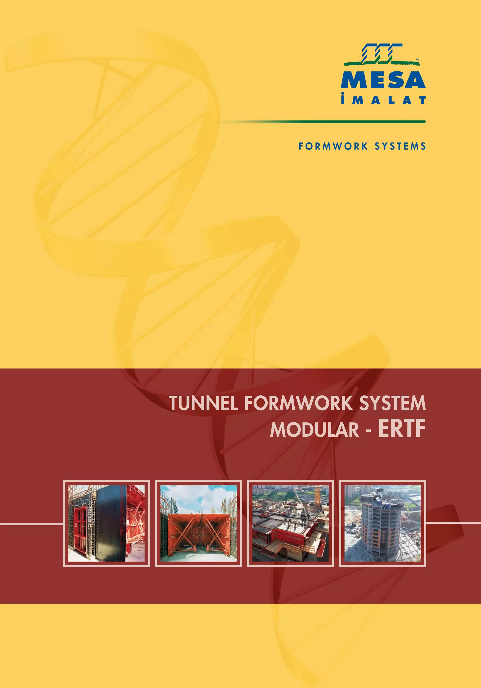
FORMWORK SYSTEMS
MODULAR-ERTF
TUNNEL FORMWORK SYSTEM
•Tunnel Formwork System
provides fast project completion
with least workmanship costs.
•Smooth concrete surfaces and
dimensional accuracy eliminates
finishing works like plastering
•The system creates efficient load-
bearing structures which are known as
the most earthquake resistant structures.
Tunnel formwork is a system that
allows casting of walls and slabs
in one operation on a daily cycle.
Construction durations are
reduced significantly by this rapid
system when compared to
conventional methods. Tunnel
form system brings speed, quality
and accuracy to concrete
construction and provides big
savings in finishing and M&E
works.
MODULAR-ERTF
TUNNEL FORMWORK SYSTEM
FORMWORK SYSTEMS
The savings from less
workmanship & duration can
reach up to almost 50%. Tunnel
form can be reused up to 500
times without any reconditioning.
Hi-tech technologies for steel
formwork production make
tunnel forms strong & durable.
ERTFMODULAR-ERTF
TUNNEL FORMWORK SYSTEM
FORMWORK SYSTEMS
Tunnel form system is preferred for all types of building projects
due to its speed and quality.
DESIGN & ENGINEERING
TUNNEL FORMWORK SYSTEM
FORMWORK SYSTEMS
MESA IMALAT is established by a dynamic
group of highly qualified technical staff with
strong engineering background.
Innovative products are designed and improved
constantly by connecting experience with
engineering skills.
It is our priority target to provide the most
suitable and smart formwork solution to every
construction project by working in a customer-
oriented fashion. In order to reach this target
we are offering all necessary technical support
as a solution partner to our customers starting
from the first day of their project until
completion.
All design, research & development studies are
supported by hi-tech computer infrastructure.
Innovative information systems are continuously
renewed to sustain successful studies. Besides
heavy hardware support MESA IMALAT also
uses original software systems which are
specifically developed and improved for our
needs.
ERTFPRODUCTION & QUALITY
TUNNEL FORMWORK SYSTEM
FORMWORK SYSTEMS
ERTF
MESA ‹MALAT's production
lines are designed with latest
production technologies.
State-of the-art machineries
have been developed to
manufacture specific products
which enable us to improve
our quality standards and
production speed.
Entire production process is
run by highly qualified
personnel whose skills are
upgraded through continuous
in-house training
programmes.
PRODUCTION & QUALITY
TUNNEL FORMWORK SYSTEM
FORMWORK SYSTEMS
Hi-tech production techniques
enable MESA IMALAT to produce
standard and special production
with same speed & high quality
which provides utmost customer
satisfaction
Machineries which are
specifically developed for MESA
IMALAT, provides fast production
with excellent welding quality &
dimensional accuracy.
Total quality concept is a
company policy which is
implemented without any
compromise. Our commitment
to quality is sustained by
continuous control of production
process by using latest
information technologies.
ERTFAFTER SALES SERVICES & TRAINING
“After Sales Service” is an integral part of MESA
IMALAT’s company policy.
Our experienced technical personnel will be at
our customer’s service on-site wherever their
project is located around the world.
At all projects the assembly of formwork and first
casting of concrete will take place under the
supervision of MESA IMALAT’s technical staff. In
this manner not only the correct implementation
of the system is secured but also training of
contractor’s site personnel is done.
TUNNEL FORMWORK SYSTEM
FORMWORK SYSTEMS
In accordance with our quality system and customer-
oriented service policy the maximum importance is given
for the training of MESA personnel. In the meantime
MESA IMALAT offers to her customers training &
certification programmes related to safe and proper
implementation of formwork systems.
DAILY CYCLE
TUNNEL FORMWORK SYSTEM
FORMWORK SYSTEMS
Foundation completed as
per construction drawings.
Reinforcement wire mesh & bars of the
concrete walls are installed
First half-tunnel is taken to place by crane
in accordance to the formwork layout.
Bottom of tunnel form is set levelled with
the line on the kickers by the help of the
jacks mounted on the vertical panels.
Block-outs for door/window openings are
assembled on vertical surface. Electrical
conduits are installed. Cones and tie rods
are placed.
Before the first casting with tunnel form,
kickers should be cast in order to position
the load bearing concrete walls.
DAILY CYCLE
Slab reinforcement mesh/bars are installed.
Kicker forms for next level are fixed on the
tunnels. Final checks are performed before
concreting. Insulation curtains are placed
for night-time heating at cold weathers.
2nd Half Tunnel is taken to its place. Block-outs
are assembled .The verticality of the half tunnels
is set using the triangulation wheel. Two half
tunnels are locked by the roof locks. Cones &
tie-rods are placed.
All tunnel form units for the 1st phase are
located as explained above. End-wall forms
are positioned. After adjusting verticality tie-
rods are fastened. Horizontal surface is
oiled. Electrical conduits are installed.
Block-outs for slab openings and slab/wall
stop-ends are set in place.
TUNNEL FORMWORK SYSTEM
FORMWORK SYSTEMS
2nd half-tunnel shall be removed after back
propping first half. Stripping & gable-end
platforms are also assembled around the
perimeter of the building. Tunnel forms will
be stripped-out on those platforms starting
from first floor.
Next morning starts with stripping of tunnel forms.
Also reinforcement mesh & bars are installed for
the next phase. Half tunnels are loosen from
connecting components and block-outs. Half
tunnels are moved on the rollers and pulled-out
by the crane to the next phase/level by the help of
lifting triangle.Vertical panel surface is cleaned
and oiled while stripping the half-tunnel.
Concreting done starting from first inside walls
towards end walls and finally slab concrete.
Plastic curtains are closed and each unit is
heated by simple heaters throughout the night
for curing purpose at cold weather.
At every span the slab is back-propped after
first half tunnel is removed.
ADVANTAGES OF MODULAR-ERTF
Bottom tie-rod locations on tunnel forms are elevated to
ensure that kicker concrete would remain below this
level even after any uncontrolled casting of kicker.
Kicker forms in bigger section enable long-lasting quality
implementation.
Standard size back-panels can easily be adapted
to any span by using extension panels. In this way
panels can easily be reused at new projects.
It eliminates the need for back-panels with special
dimensions.
Provides better concrete finish at joints of
extensions panels
Height kickers makes it easier to adjust tunnel heights
which eliminates levelling mistakes of the foundation.
Elevated Bottom Tie-Rod &
Higher Kicker Concrete
Modular Back-Panel with
Extension Adapter
TUNNEL FORMWORK SYSTEM
FORMWORK SYSTEMS
Enables to use the same platform at several
floors with different slab finish lines.
For slabs with poor concrete finishing,
assembly of platform requires less
workmanship since the timber surface is
inserted under the slab
Half-tunnels can easily be moved and
stripped on platforms by the help of rollers
which are used instead of wheels. It is
placed under vertical panel of half-tunnels
above the slab.
It reduces vertical panel price by
cancelling the wheels and also simplify
storage of vertical panels.
Formwork weight will not affect stripping
platform as the tunnel forms are carried by
the rollers during their movement.
Stripping Platforms Mounted
Under-Slab
Roller for Stripping Tunnels
ADVANTAGES OF MODULAR-ERTF
Vertical panels are produced in standard heights.
It can be used for half-tunnels and also for end-walls
which reduces different types of panels on site.
Vertical panels are used with upper extension panels
to reach different floor heights easily. In this way
panels can easily be reused at new projects.
Vertical panels can be used as wall-forms too.
Asymmetrical Lifting Triangle
The lifting triangle is designed so that it can be set in
place with the centre of gravity of the tunnel still inside
the building by the help of its asymmetrical shape.
In this way the load of tunnels which are moved on
the rollers won't be taken by the stripping platforms.
Easier to handle and transport than classic lifting
triangles.
Modular Vertical Panel with
Extension Adapter
TUNNEL FORMWORK SYSTEM
FORMWORK SYSTEMS
ERTF Telescopic Push-Pull Prop
Standard push-pull props can easily be used at
any tunnel span by the help of its telescopic
design. It eliminates the need for several different
types of props.
ERTF Push-Pull Props makes it very easy to adjust
the height & level horizontal panels of tunnel form.
Lifting up the the control arm will simply move the
horizontal panel down. The arm is locked once
the panel is adjusted properly.
Modular Horizontal Panel
with Extension Adapter
Horizontal panels are produced in standard
width and can be used at any span
dimension with extension adapter panels.
In this way panels can easily be reused
at new projects.
It eliminates the need for back-panels with
special dimensions.
Provides better concrete finish at joints of
extension panels.
MODULAR-ERTF
TUNNEL FORMWORK SYSTEM
FORMWORK SYSTEMS
FORMWORK SYSTEMS
Block-Out
Working Platform
Gable-end Platform
End-wall Panel
ERTF SYSTEM SECTION
Lifting Triangle
Horizontal Panel
Kicker Form
Slab Stopend
Vertical Panel
Push-pell Prop.
Wheeled Prop.
Stripping Platform
MODULAR-ERTF
More than 1.5 million units of apartments and hundreds of office buildings
& hotels have been completed with MESA Tunnel Form System in 5 continents
& 30 countries worldwide.
TUNNEL FORMWORK SYSTEM
FORMWORK SYSTEMS
ERTFMODULAR-ERTF
TUNNEL FORMWORK SYSTEM
FORMWORK SYSTEMS
MODULAR-ERTF
TUNNEL FORMWORK SYSTEM
FORMWORK SYSTEMS
MODULAR-ERTF
TUNNEL FORMWORK SYSTEM
FORMWORK SYSTEMS
MODULAR-ERTF
TUNNEL FORMWORK SYSTEM
FORMWORK SYSTEMS
MODULAR-ERTF
TUNNEL FORMWORK SYSTEM
FORMWORK SYSTEMS
MODULAR-ERTF
TUNNEL FORMWORK SYSTEM
FORMWORK SYSTEMS
Std. Back Panel
POS. LENGTH WEIGHT
NO (mm) (kg)
M.T.EAS.001050 (1050+93) x (2763+93) 237.69
M.T.EAS.001350 (1350+93) x (2763+93) 291.86
M.T.EAS.001650 (1650+93) x (2763+93) 336.62
M.T.EAS.001950 (1950+93) x (2763+93) 395.64
M.T.EAS.002250 (2250+93) x (2763+93) 443.34
M.T.EAS.002550 (2550+93) x (2763+93) 87.58
M.T.EAS.002850 (2850+93) x (2763+93) 546.82
Std. Horizontal Panel
POS. LENGTH WEIGHT
NO (mm) (kg)
M.Y.EYS.U10850 (850+63) x 2500 128.69
M.Y.EYS.U11150 (1150+63) x 2500 158.42
M.Y.EYS.U11450 (1450+63) x 2500 191.96
M.Y.EYS.U11750 (1750+63) x 2500 224.18
M.Y.EYS.U12050 (2050+63) x 2500 286.30
M.Y.EYS.U12350 (2350+63) x 2500 319.60
M.Y.EYS.U12650 (2650+63) x 2500 392.30
M.Y.EYS.U20850 (850+63) x 1250 69.02
M.Y.EYS.U21150 (1150+63) x 1250 86.50
M.Y.EYS.U21450 (1450+63) x 1250 103.45
M.Y.EYS.U21750 (1750+63) x 1250 119.95
M.Y.EYS.U22050 (2050+63) x 1250 163.76
M.Y.EYS.U22350 (2350+63) x 1250 184.02
Std. Vertical Panel
POS. LENGTH WEIGHT
NO (mm) (kg)
M.T.EDS.002500 2500 x 2500 442.36
M.T.EDS.001250 1250 x 2500 240.02
M.T.EDS.002500 2500 x 2500
M.T.EDS.001250 1250 x 2500
Vertical Panel Upper Adaptor
POS. LENGTH WEIGHT
NO (mm) (kg)
M.T.EUA.000000 x 2500
M.T.EUA.000000 x 1250
M.T.EUA.000000 200 x 2500 37.5
M.T.EUA.000000 200 x 1250 18.75
LIST OF COMPONENTS
FORMWORK SYSTEMS
Vertical Panel Support Bolt
POS. LENGTH WEIGHT
NO (mm) (kg)
M.Q.KMC.000000 0.41
LIST OF COMPONENTS
Vertical Panel Upper Bolt
POS. LENGTH WEIGHT
NO (mm) (kg)
M.T.EUA.000000 533 x 2500 93028
M.T.EUA.000000 533 x 1250 46.64
ERTF Push Pull Prop
POS. LENGTH WEIGHT
NO (mm) (kg)
M.C.EKS.000000 40.08
ERTF Wheeled Prop (Set)
POS. LENGTH WEIGHT
NO (mm) (kg)
M.C.EKS.000000 25.48
ERTF Wheeled Prop Support (Set)
POS. LENGTH WEIGHT
NO (mm) (kg)
M.C.EYC.000001 L=850-1150 20.60
M.C.EYC.000002 L=1450-1750 23.90
M.C.EYC.000003 L=2050-2350 26.07
ERTF Supporting Tube (2 pcs set)
POS. LENGTH WEIGHT
NO (mm) (kg)
M.T.EYD.000001 L= 850-1150 14.58
M.T.EYD.000002 L=1450-1750 16.68
M.T.EYD.000003 L=2050-2350 18.10
Std. Lifting Beam
POS. LENGTH WEIGHT
NO (mm) (kg)
M.V.TPD.000500 L= 500 mm 9.57
M.V.TPD.001000 L=1000 mm 19.34
M.V.TPD.002000 L=2000 mm 35.32
M.V.TPD.003000 L=3000 mm 53.41
M.V.TPD.004000 L=4000 mm 69.43
M.V.TPD.004500 L=4500 mm 77.51
M.V.TPD.005000 L=5000 mm 85.7
Std. Wall Stopend
POS. LENGTH WEIGHT
NO (mm) (kg)
M.S.PAS.000000 p =148 L=3033 59.73
M.S.PAS.000000 p =158 L=3033 61.45
M.S.PAS.000000 p =178 L=3033 64.25
M.S.PAS.000000 p =198 L=3033 67.03
M.S.PAS.000000 p =248 L=3033 70.55
Slab Stoppend
POS. LENGTH WEIGHT
NO (mm) (kg)
M.S.DAS.001045 (1045+93) x 150 18.55
M.S.DAS.001345 (1345+93) x 150 21.71
M.S.DAS.001645 (1645+93) x 150 24.93
M.S.DAS.001945 (1945+93) x 150 28.12
M.S.DAS.002245 (2245+93) x 150 34.30
M.S.DAS.002545 (2545+93) x 150 37.45
M.S.DAS.002845 (2845+93) x 150 41.86
Straight Kicker Form
POS. LENGTH WEIGHT
NO (mm) (kg)
M.A.AKD.000625 L=625 mm 11.85
M.A.AKD.001250 L=1250 mm 16.94
M.A.AKD.002500 L=2500 mm 32.65
M.A.AKD.003750 L=3750 mm 47.97
M.A.AKD.005000 L=5000mm 63.29
LIST OF COMPONENTS
FORMWORK SYSTEMS
LIST OF COMPONENTS
Straight Inner Kicker Form
POS. LENGTH WEIGHT
NO (mm) (kg)
M.A.AKA.001498 L=1498 mm 19.67
M.A.AKA.001798 L=1798 mm 23.36
M.A.AKA.002098 L=2098 mm 27.01
M.A.AKA.002398 L=2398 mm 30.01
M.A.AKA.002698 L=2698 mm 34.37
M.A.AKA.002998 L=2998 mm 38.05
M.A.AKA.003298 L=3298 mm 41.72
M.A.AKA.003598 L=3598 mm 45.72
M.A.AKA.003898 L=3898 mm 49.08
M.A.AKA.004198 L=4198 mm 52.76
M.A.AKA.004498 L=4498 mm 56.44
M.A.AKA.004798 L=4798 mm 60.11
M.A.AKA.005098 L=5098 mm 63.79
L-Shaped Kicker Form
POS. LENGTH WEIGHT
NO (mm) (kg)
M.A.AKG.002593 L=2593+299 37.1
Single Sided Kicker Seat
POS. LENGTH WEIGHT
NO (mm) (kg)
M.A.MAT.000000 p:198 d:150 4.24
Double Sided Kicker Seat
POS. LENGTH WEIGHT
NO (mm) (kg)
M.A.MAC.000000 p:198 d:150 5.62
Kicker Clamp (Outer)
POS. LENGTH WEIGHT
NO (mm) (kg)
M.A.MTK.000000 p:198 d:273 3.39
Kicker Clamp (Inner)
POS. LENGTH WEIGHT
NO (mm) (kg)
M.A.MCK.000000 p:198 d:220 3.08
Panel Support Bracket
POS. LENGTH WEIGHT
NO (mm) (kg)
M.F.EPD.000000 24.14
Platform Support Bracket
POS. LENGTH WEIGHT
NO (mm) (kg)
M.G.EPE.000000 3.59
Platform
POS. LENGTH WEIGHT
NO (mm) (kg)
M.G.PLT.001250 L=1250 26.35
M.G.PLT.002500 L=2500 48.06
Security Post
POS. LENGTH WEIGHT
NO (mm) (kg)
M.J.BKP.000000 L=1400 5.16
Platform Ladder
POS. LENGTH WEIGHT
NO (mm) (kg)
M.J.BIM.00000 13.43
Ø25 x 200 Pin
POS. LENGTH WEIGHT
NO (mm) (kg)
Z.A.PIM.025200 0.20
LIST OF COMPONENTS
FORMWORK SYSTEMS
Swivel Coupler Ø48/Ø48
POS. LENGTH WEIGHT
NO (mm) (kg)
M.Q.HK1.000000 1.17
Console (Set)
POS. LENGTH WEIGHT
NO (mm) (kg)
M.J.A12.000000 11.00
Door Block Out
POS. LENGTH WEIGHT
NO (mm) (kg)
M.R.PBR.000000 W x W x p
Slab Block Out
POS. LENGTH WEIGHT
NO (mm) (kg)
M.R.PPR.000000 W x W x p
Lifting Triangle 1000 x 500
POS. LENGTH WEIGHT
NO (mm) (kg)
M.Z.ZUK.000000 71.72
ERTF-Asymmetric Lifting Triangle (Small)
POS. LENGTH WEIGHT
NO (mm) (kg)
M.Z.ZAK.000000 187.24
Back Panel Spanner
POS. LENGTH WEIGHT
NO (mm) (kg)
M.F.MAA.000000 1.87
LIST OF COMPONENTS
Screw Jack Spanner
POS. LENGTH WEIGHT
NO (mm) (kg)
M.T.MTA.000000 1.10
LIST OF COMPONENTS
Roller
POS. LENGTH WEIGHT
NO (mm) (kg)
M.Z.YER.000001 (Roller H=53) 14.56
M.Z.YER.000002 (Roller H=73) 17.35
Center U (Normal)
POS. LENGTH WEIGHT
NO (mm) (kg)
Z.A.MRU.000043 L=43 0.3
Roof Lock
POS. LENGTH WEIGHT
NO (mm) (kg)
Z.A.KNK.000000 0.5
ERTF-Free Wheel (Set)
POS. LENGTH WEIGHT
NO (mm) (kg)
M.Z.YES.000000 15.63
ERTF-Back Panel Wheet with Jack
POS. LENGTH WEIGHT
NO (mm) (kg)
M.Z.YEP.000000 15.63
ERTF-Panel Screw Jack
POS. LENGTH WEIGHT
NO (mm) (kg)
M.U.ED1.000000 8.69
FORMWORK SYSTEMS
LIST OF COMPONENTS
Conical Bolt
POS. LENGTH WEIGHT
NO (mm) (kg)
M.Q.KTC.000000 0.26
Ø24 Tie Rod - Galvanised
POS. LENGTH WEIGHT
NO (mm) (kg)
Z.A.SPL.000024 L=1000 mm 3.00
Ø24 Wing Nut
POS. LENGTH WEIGHT
NO (mm) (kg)
Z.A.SPS.000024 0.78
10x100x100 (27) Washer
POS. LENGTH WEIGHT
NO (mm) (kg)
Z.A.SDP.000024 0.73
10x100x100 Washer W/Notch (Ø24)
POS. LENGTH WEIGHT
NO (mm) (kg)
Z.A.STP.000024 0.92
Spacer
POS. LENGTH WEIGHT
NO (mm) (kg)
M.Q.KON.000128 Ø40x50 L=128 1.04
M.Q.KON.000148 Ø40x50 L=148 1.25
M.Q.KON.000158 Ø40x50 L=158 1.35
M.Q.KON.000178 Ø40x50 L=178 1.55
M.Q.KON.000198 Ø40x50 L=198 1.70
M.Q.KON.000218 Ø40x50 L=218 1.77
M.Q.KON.000248 Ø40x50 L=248 2.01
Guard Rail (Side)
POS. LENGTH WEIGHT
NO (mm) (kg)
M.J.IYK.000000 L=1390 3.7
LIST OF COMPONENTS
Horizontal Adaptor
POS. LENGTH WEIGHT
NO (mm) (kg)
M.Y.EYA.000000 L=2500
Console (Set)
POS. LENGTH WEIGHT
NO (mm) (kg)
M.J.A.12.000000 10.3
Gable and Frame Bracket
POS. LENGTH WEIGHT
NO (mm) (kg)
M.L.TTA.000000 53.5
Demountable Triangular Bracket
POS. LENGTH WEIGHT
NO (mm) (kg)
M.L.KSO.006000 L=6000 233
M.L.KSO.007000 L=7000 252.5
FORMWORK SYSTEMS
LIST OF COMPONENTS
Platform Support Bracket
POS. LENGTH WEIGHT
NO (mm) (kg)
M.M.SPE.000000 L=1088 4.4
Platform Seat
POS. LENGTH WEIGHT
NO (mm) (kg)
M.M.PSE.000000 8.25
Ø17 Wing Nut
POS. LENGTH WEIGHT
NO (mm) (kg)
Z.A.SPS.000017 0.49
Horizontal Panel Spanner
POS. LENGTH WEIGHT
NO (mm) (kg)
3.5
MESA FORMWORK SYSTEMS
World-Wide
5 Continets
30 Countries
Ertf
Ertf

Ertf

  • 4.
    FORMWORK SYSTEMS MODULAR-ERTF TUNNEL FORMWORKSYSTEM •Tunnel Formwork System provides fast project completion with least workmanship costs. •Smooth concrete surfaces and dimensional accuracy eliminates finishing works like plastering
  • 5.
    •The system createsefficient load- bearing structures which are known as the most earthquake resistant structures.
  • 6.
    Tunnel formwork isa system that allows casting of walls and slabs in one operation on a daily cycle. Construction durations are reduced significantly by this rapid system when compared to conventional methods. Tunnel form system brings speed, quality and accuracy to concrete construction and provides big savings in finishing and M&E works. MODULAR-ERTF TUNNEL FORMWORK SYSTEM FORMWORK SYSTEMS
  • 7.
    The savings fromless workmanship & duration can reach up to almost 50%. Tunnel form can be reused up to 500 times without any reconditioning. Hi-tech technologies for steel formwork production make tunnel forms strong & durable.
  • 8.
  • 9.
    Tunnel form systemis preferred for all types of building projects due to its speed and quality.
  • 10.
    DESIGN & ENGINEERING TUNNELFORMWORK SYSTEM FORMWORK SYSTEMS
  • 11.
    MESA IMALAT isestablished by a dynamic group of highly qualified technical staff with strong engineering background. Innovative products are designed and improved constantly by connecting experience with engineering skills. It is our priority target to provide the most suitable and smart formwork solution to every construction project by working in a customer- oriented fashion. In order to reach this target we are offering all necessary technical support as a solution partner to our customers starting from the first day of their project until completion. All design, research & development studies are supported by hi-tech computer infrastructure. Innovative information systems are continuously renewed to sustain successful studies. Besides heavy hardware support MESA IMALAT also uses original software systems which are specifically developed and improved for our needs.
  • 12.
    ERTFPRODUCTION & QUALITY TUNNELFORMWORK SYSTEM FORMWORK SYSTEMS
  • 14.
    ERTF MESA ‹MALAT's production linesare designed with latest production technologies. State-of the-art machineries have been developed to manufacture specific products which enable us to improve our quality standards and production speed. Entire production process is run by highly qualified personnel whose skills are upgraded through continuous in-house training programmes. PRODUCTION & QUALITY TUNNEL FORMWORK SYSTEM FORMWORK SYSTEMS
  • 15.
    Hi-tech production techniques enableMESA IMALAT to produce standard and special production with same speed & high quality which provides utmost customer satisfaction Machineries which are specifically developed for MESA IMALAT, provides fast production with excellent welding quality & dimensional accuracy. Total quality concept is a company policy which is implemented without any compromise. Our commitment to quality is sustained by continuous control of production process by using latest information technologies.
  • 16.
    ERTFAFTER SALES SERVICES& TRAINING “After Sales Service” is an integral part of MESA IMALAT’s company policy. Our experienced technical personnel will be at our customer’s service on-site wherever their project is located around the world. At all projects the assembly of formwork and first casting of concrete will take place under the supervision of MESA IMALAT’s technical staff. In this manner not only the correct implementation of the system is secured but also training of contractor’s site personnel is done. TUNNEL FORMWORK SYSTEM FORMWORK SYSTEMS
  • 17.
    In accordance withour quality system and customer- oriented service policy the maximum importance is given for the training of MESA personnel. In the meantime MESA IMALAT offers to her customers training & certification programmes related to safe and proper implementation of formwork systems.
  • 18.
    DAILY CYCLE TUNNEL FORMWORKSYSTEM FORMWORK SYSTEMS
  • 19.
    Foundation completed as perconstruction drawings. Reinforcement wire mesh & bars of the concrete walls are installed First half-tunnel is taken to place by crane in accordance to the formwork layout. Bottom of tunnel form is set levelled with the line on the kickers by the help of the jacks mounted on the vertical panels. Block-outs for door/window openings are assembled on vertical surface. Electrical conduits are installed. Cones and tie rods are placed. Before the first casting with tunnel form, kickers should be cast in order to position the load bearing concrete walls.
  • 20.
    DAILY CYCLE Slab reinforcementmesh/bars are installed. Kicker forms for next level are fixed on the tunnels. Final checks are performed before concreting. Insulation curtains are placed for night-time heating at cold weathers. 2nd Half Tunnel is taken to its place. Block-outs are assembled .The verticality of the half tunnels is set using the triangulation wheel. Two half tunnels are locked by the roof locks. Cones & tie-rods are placed. All tunnel form units for the 1st phase are located as explained above. End-wall forms are positioned. After adjusting verticality tie- rods are fastened. Horizontal surface is oiled. Electrical conduits are installed. Block-outs for slab openings and slab/wall stop-ends are set in place. TUNNEL FORMWORK SYSTEM FORMWORK SYSTEMS
  • 21.
    2nd half-tunnel shallbe removed after back propping first half. Stripping & gable-end platforms are also assembled around the perimeter of the building. Tunnel forms will be stripped-out on those platforms starting from first floor. Next morning starts with stripping of tunnel forms. Also reinforcement mesh & bars are installed for the next phase. Half tunnels are loosen from connecting components and block-outs. Half tunnels are moved on the rollers and pulled-out by the crane to the next phase/level by the help of lifting triangle.Vertical panel surface is cleaned and oiled while stripping the half-tunnel. Concreting done starting from first inside walls towards end walls and finally slab concrete. Plastic curtains are closed and each unit is heated by simple heaters throughout the night for curing purpose at cold weather. At every span the slab is back-propped after first half tunnel is removed.
  • 22.
    ADVANTAGES OF MODULAR-ERTF Bottomtie-rod locations on tunnel forms are elevated to ensure that kicker concrete would remain below this level even after any uncontrolled casting of kicker. Kicker forms in bigger section enable long-lasting quality implementation. Standard size back-panels can easily be adapted to any span by using extension panels. In this way panels can easily be reused at new projects. It eliminates the need for back-panels with special dimensions. Provides better concrete finish at joints of extensions panels Height kickers makes it easier to adjust tunnel heights which eliminates levelling mistakes of the foundation. Elevated Bottom Tie-Rod & Higher Kicker Concrete Modular Back-Panel with Extension Adapter TUNNEL FORMWORK SYSTEM FORMWORK SYSTEMS
  • 23.
    Enables to usethe same platform at several floors with different slab finish lines. For slabs with poor concrete finishing, assembly of platform requires less workmanship since the timber surface is inserted under the slab Half-tunnels can easily be moved and stripped on platforms by the help of rollers which are used instead of wheels. It is placed under vertical panel of half-tunnels above the slab. It reduces vertical panel price by cancelling the wheels and also simplify storage of vertical panels. Formwork weight will not affect stripping platform as the tunnel forms are carried by the rollers during their movement. Stripping Platforms Mounted Under-Slab Roller for Stripping Tunnels
  • 24.
    ADVANTAGES OF MODULAR-ERTF Verticalpanels are produced in standard heights. It can be used for half-tunnels and also for end-walls which reduces different types of panels on site. Vertical panels are used with upper extension panels to reach different floor heights easily. In this way panels can easily be reused at new projects. Vertical panels can be used as wall-forms too. Asymmetrical Lifting Triangle The lifting triangle is designed so that it can be set in place with the centre of gravity of the tunnel still inside the building by the help of its asymmetrical shape. In this way the load of tunnels which are moved on the rollers won't be taken by the stripping platforms. Easier to handle and transport than classic lifting triangles. Modular Vertical Panel with Extension Adapter TUNNEL FORMWORK SYSTEM FORMWORK SYSTEMS
  • 25.
    ERTF Telescopic Push-PullProp Standard push-pull props can easily be used at any tunnel span by the help of its telescopic design. It eliminates the need for several different types of props. ERTF Push-Pull Props makes it very easy to adjust the height & level horizontal panels of tunnel form. Lifting up the the control arm will simply move the horizontal panel down. The arm is locked once the panel is adjusted properly. Modular Horizontal Panel with Extension Adapter Horizontal panels are produced in standard width and can be used at any span dimension with extension adapter panels. In this way panels can easily be reused at new projects. It eliminates the need for back-panels with special dimensions. Provides better concrete finish at joints of extension panels.
  • 26.
  • 28.
  • 29.
    ERTF SYSTEM SECTION LiftingTriangle Horizontal Panel Kicker Form Slab Stopend Vertical Panel Push-pell Prop. Wheeled Prop. Stripping Platform
  • 30.
    MODULAR-ERTF More than 1.5million units of apartments and hundreds of office buildings & hotels have been completed with MESA Tunnel Form System in 5 continents & 30 countries worldwide. TUNNEL FORMWORK SYSTEM FORMWORK SYSTEMS
  • 32.
  • 34.
  • 36.
  • 38.
  • 40.
  • 42.
  • 44.
    Std. Back Panel POS.LENGTH WEIGHT NO (mm) (kg) M.T.EAS.001050 (1050+93) x (2763+93) 237.69 M.T.EAS.001350 (1350+93) x (2763+93) 291.86 M.T.EAS.001650 (1650+93) x (2763+93) 336.62 M.T.EAS.001950 (1950+93) x (2763+93) 395.64 M.T.EAS.002250 (2250+93) x (2763+93) 443.34 M.T.EAS.002550 (2550+93) x (2763+93) 87.58 M.T.EAS.002850 (2850+93) x (2763+93) 546.82 Std. Horizontal Panel POS. LENGTH WEIGHT NO (mm) (kg) M.Y.EYS.U10850 (850+63) x 2500 128.69 M.Y.EYS.U11150 (1150+63) x 2500 158.42 M.Y.EYS.U11450 (1450+63) x 2500 191.96 M.Y.EYS.U11750 (1750+63) x 2500 224.18 M.Y.EYS.U12050 (2050+63) x 2500 286.30 M.Y.EYS.U12350 (2350+63) x 2500 319.60 M.Y.EYS.U12650 (2650+63) x 2500 392.30 M.Y.EYS.U20850 (850+63) x 1250 69.02 M.Y.EYS.U21150 (1150+63) x 1250 86.50 M.Y.EYS.U21450 (1450+63) x 1250 103.45 M.Y.EYS.U21750 (1750+63) x 1250 119.95 M.Y.EYS.U22050 (2050+63) x 1250 163.76 M.Y.EYS.U22350 (2350+63) x 1250 184.02 Std. Vertical Panel POS. LENGTH WEIGHT NO (mm) (kg) M.T.EDS.002500 2500 x 2500 442.36 M.T.EDS.001250 1250 x 2500 240.02 M.T.EDS.002500 2500 x 2500 M.T.EDS.001250 1250 x 2500 Vertical Panel Upper Adaptor POS. LENGTH WEIGHT NO (mm) (kg) M.T.EUA.000000 x 2500 M.T.EUA.000000 x 1250 M.T.EUA.000000 200 x 2500 37.5 M.T.EUA.000000 200 x 1250 18.75 LIST OF COMPONENTS FORMWORK SYSTEMS
  • 45.
    Vertical Panel SupportBolt POS. LENGTH WEIGHT NO (mm) (kg) M.Q.KMC.000000 0.41 LIST OF COMPONENTS Vertical Panel Upper Bolt POS. LENGTH WEIGHT NO (mm) (kg) M.T.EUA.000000 533 x 2500 93028 M.T.EUA.000000 533 x 1250 46.64 ERTF Push Pull Prop POS. LENGTH WEIGHT NO (mm) (kg) M.C.EKS.000000 40.08 ERTF Wheeled Prop (Set) POS. LENGTH WEIGHT NO (mm) (kg) M.C.EKS.000000 25.48 ERTF Wheeled Prop Support (Set) POS. LENGTH WEIGHT NO (mm) (kg) M.C.EYC.000001 L=850-1150 20.60 M.C.EYC.000002 L=1450-1750 23.90 M.C.EYC.000003 L=2050-2350 26.07 ERTF Supporting Tube (2 pcs set) POS. LENGTH WEIGHT NO (mm) (kg) M.T.EYD.000001 L= 850-1150 14.58 M.T.EYD.000002 L=1450-1750 16.68 M.T.EYD.000003 L=2050-2350 18.10
  • 46.
    Std. Lifting Beam POS.LENGTH WEIGHT NO (mm) (kg) M.V.TPD.000500 L= 500 mm 9.57 M.V.TPD.001000 L=1000 mm 19.34 M.V.TPD.002000 L=2000 mm 35.32 M.V.TPD.003000 L=3000 mm 53.41 M.V.TPD.004000 L=4000 mm 69.43 M.V.TPD.004500 L=4500 mm 77.51 M.V.TPD.005000 L=5000 mm 85.7 Std. Wall Stopend POS. LENGTH WEIGHT NO (mm) (kg) M.S.PAS.000000 p =148 L=3033 59.73 M.S.PAS.000000 p =158 L=3033 61.45 M.S.PAS.000000 p =178 L=3033 64.25 M.S.PAS.000000 p =198 L=3033 67.03 M.S.PAS.000000 p =248 L=3033 70.55 Slab Stoppend POS. LENGTH WEIGHT NO (mm) (kg) M.S.DAS.001045 (1045+93) x 150 18.55 M.S.DAS.001345 (1345+93) x 150 21.71 M.S.DAS.001645 (1645+93) x 150 24.93 M.S.DAS.001945 (1945+93) x 150 28.12 M.S.DAS.002245 (2245+93) x 150 34.30 M.S.DAS.002545 (2545+93) x 150 37.45 M.S.DAS.002845 (2845+93) x 150 41.86 Straight Kicker Form POS. LENGTH WEIGHT NO (mm) (kg) M.A.AKD.000625 L=625 mm 11.85 M.A.AKD.001250 L=1250 mm 16.94 M.A.AKD.002500 L=2500 mm 32.65 M.A.AKD.003750 L=3750 mm 47.97 M.A.AKD.005000 L=5000mm 63.29 LIST OF COMPONENTS FORMWORK SYSTEMS
  • 47.
    LIST OF COMPONENTS StraightInner Kicker Form POS. LENGTH WEIGHT NO (mm) (kg) M.A.AKA.001498 L=1498 mm 19.67 M.A.AKA.001798 L=1798 mm 23.36 M.A.AKA.002098 L=2098 mm 27.01 M.A.AKA.002398 L=2398 mm 30.01 M.A.AKA.002698 L=2698 mm 34.37 M.A.AKA.002998 L=2998 mm 38.05 M.A.AKA.003298 L=3298 mm 41.72 M.A.AKA.003598 L=3598 mm 45.72 M.A.AKA.003898 L=3898 mm 49.08 M.A.AKA.004198 L=4198 mm 52.76 M.A.AKA.004498 L=4498 mm 56.44 M.A.AKA.004798 L=4798 mm 60.11 M.A.AKA.005098 L=5098 mm 63.79 L-Shaped Kicker Form POS. LENGTH WEIGHT NO (mm) (kg) M.A.AKG.002593 L=2593+299 37.1 Single Sided Kicker Seat POS. LENGTH WEIGHT NO (mm) (kg) M.A.MAT.000000 p:198 d:150 4.24 Double Sided Kicker Seat POS. LENGTH WEIGHT NO (mm) (kg) M.A.MAC.000000 p:198 d:150 5.62 Kicker Clamp (Outer) POS. LENGTH WEIGHT NO (mm) (kg) M.A.MTK.000000 p:198 d:273 3.39 Kicker Clamp (Inner) POS. LENGTH WEIGHT NO (mm) (kg) M.A.MCK.000000 p:198 d:220 3.08
  • 48.
    Panel Support Bracket POS.LENGTH WEIGHT NO (mm) (kg) M.F.EPD.000000 24.14 Platform Support Bracket POS. LENGTH WEIGHT NO (mm) (kg) M.G.EPE.000000 3.59 Platform POS. LENGTH WEIGHT NO (mm) (kg) M.G.PLT.001250 L=1250 26.35 M.G.PLT.002500 L=2500 48.06 Security Post POS. LENGTH WEIGHT NO (mm) (kg) M.J.BKP.000000 L=1400 5.16 Platform Ladder POS. LENGTH WEIGHT NO (mm) (kg) M.J.BIM.00000 13.43 Ø25 x 200 Pin POS. LENGTH WEIGHT NO (mm) (kg) Z.A.PIM.025200 0.20 LIST OF COMPONENTS FORMWORK SYSTEMS
  • 49.
    Swivel Coupler Ø48/Ø48 POS.LENGTH WEIGHT NO (mm) (kg) M.Q.HK1.000000 1.17 Console (Set) POS. LENGTH WEIGHT NO (mm) (kg) M.J.A12.000000 11.00 Door Block Out POS. LENGTH WEIGHT NO (mm) (kg) M.R.PBR.000000 W x W x p Slab Block Out POS. LENGTH WEIGHT NO (mm) (kg) M.R.PPR.000000 W x W x p Lifting Triangle 1000 x 500 POS. LENGTH WEIGHT NO (mm) (kg) M.Z.ZUK.000000 71.72 ERTF-Asymmetric Lifting Triangle (Small) POS. LENGTH WEIGHT NO (mm) (kg) M.Z.ZAK.000000 187.24 Back Panel Spanner POS. LENGTH WEIGHT NO (mm) (kg) M.F.MAA.000000 1.87 LIST OF COMPONENTS
  • 50.
    Screw Jack Spanner POS.LENGTH WEIGHT NO (mm) (kg) M.T.MTA.000000 1.10 LIST OF COMPONENTS Roller POS. LENGTH WEIGHT NO (mm) (kg) M.Z.YER.000001 (Roller H=53) 14.56 M.Z.YER.000002 (Roller H=73) 17.35 Center U (Normal) POS. LENGTH WEIGHT NO (mm) (kg) Z.A.MRU.000043 L=43 0.3 Roof Lock POS. LENGTH WEIGHT NO (mm) (kg) Z.A.KNK.000000 0.5 ERTF-Free Wheel (Set) POS. LENGTH WEIGHT NO (mm) (kg) M.Z.YES.000000 15.63 ERTF-Back Panel Wheet with Jack POS. LENGTH WEIGHT NO (mm) (kg) M.Z.YEP.000000 15.63 ERTF-Panel Screw Jack POS. LENGTH WEIGHT NO (mm) (kg) M.U.ED1.000000 8.69 FORMWORK SYSTEMS
  • 51.
    LIST OF COMPONENTS ConicalBolt POS. LENGTH WEIGHT NO (mm) (kg) M.Q.KTC.000000 0.26 Ø24 Tie Rod - Galvanised POS. LENGTH WEIGHT NO (mm) (kg) Z.A.SPL.000024 L=1000 mm 3.00 Ø24 Wing Nut POS. LENGTH WEIGHT NO (mm) (kg) Z.A.SPS.000024 0.78 10x100x100 (27) Washer POS. LENGTH WEIGHT NO (mm) (kg) Z.A.SDP.000024 0.73 10x100x100 Washer W/Notch (Ø24) POS. LENGTH WEIGHT NO (mm) (kg) Z.A.STP.000024 0.92 Spacer POS. LENGTH WEIGHT NO (mm) (kg) M.Q.KON.000128 Ø40x50 L=128 1.04 M.Q.KON.000148 Ø40x50 L=148 1.25 M.Q.KON.000158 Ø40x50 L=158 1.35 M.Q.KON.000178 Ø40x50 L=178 1.55 M.Q.KON.000198 Ø40x50 L=198 1.70 M.Q.KON.000218 Ø40x50 L=218 1.77 M.Q.KON.000248 Ø40x50 L=248 2.01
  • 52.
    Guard Rail (Side) POS.LENGTH WEIGHT NO (mm) (kg) M.J.IYK.000000 L=1390 3.7 LIST OF COMPONENTS Horizontal Adaptor POS. LENGTH WEIGHT NO (mm) (kg) M.Y.EYA.000000 L=2500 Console (Set) POS. LENGTH WEIGHT NO (mm) (kg) M.J.A.12.000000 10.3 Gable and Frame Bracket POS. LENGTH WEIGHT NO (mm) (kg) M.L.TTA.000000 53.5 Demountable Triangular Bracket POS. LENGTH WEIGHT NO (mm) (kg) M.L.KSO.006000 L=6000 233 M.L.KSO.007000 L=7000 252.5 FORMWORK SYSTEMS
  • 53.
    LIST OF COMPONENTS PlatformSupport Bracket POS. LENGTH WEIGHT NO (mm) (kg) M.M.SPE.000000 L=1088 4.4 Platform Seat POS. LENGTH WEIGHT NO (mm) (kg) M.M.PSE.000000 8.25 Ø17 Wing Nut POS. LENGTH WEIGHT NO (mm) (kg) Z.A.SPS.000017 0.49 Horizontal Panel Spanner POS. LENGTH WEIGHT NO (mm) (kg) 3.5
  • 54.
    MESA FORMWORK SYSTEMS World-Wide 5Continets 30 Countries