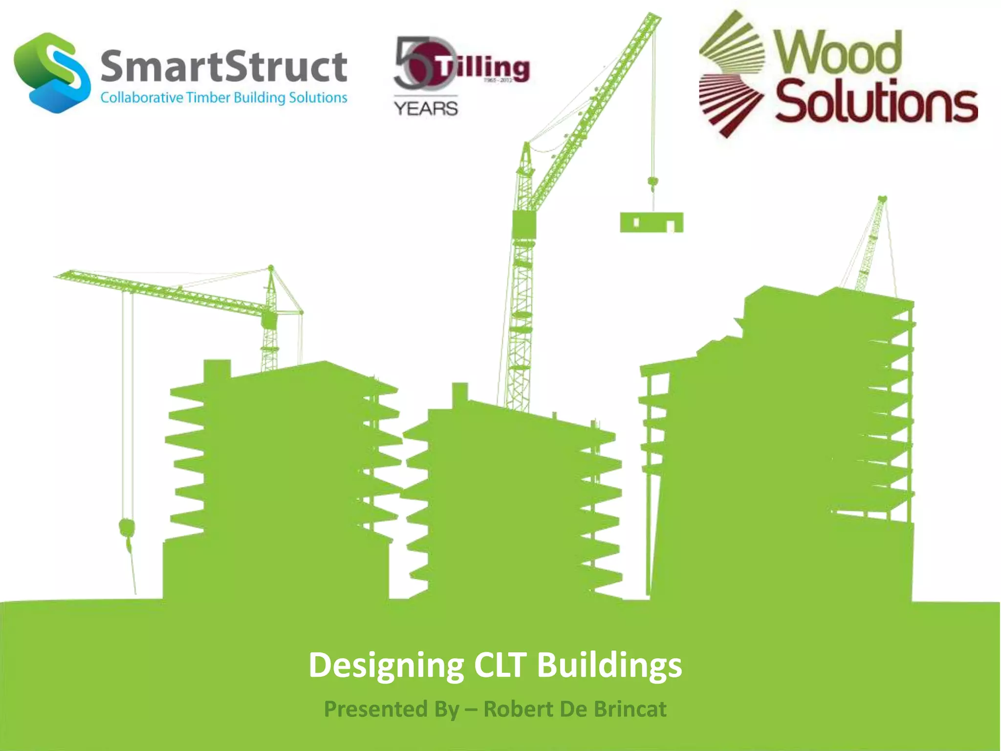
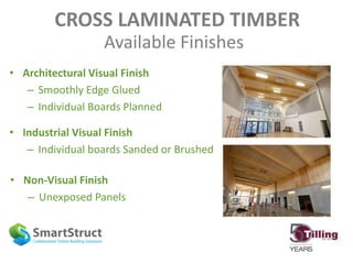
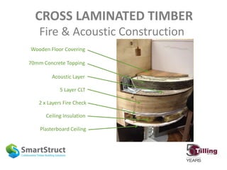
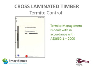
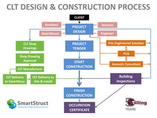
Designing CLT Buildings
Presented By – Robert De Brincat
INTRODUCTION
CLT Design Considerations
• Optimum CLT Design & Building Applications
• Strength / Serviceability / Vibration / Fire / Acoustics
• Floor, Wall & Lateral Design
CLT Supply & Design Resources
• CLT Material Properties & Supplier Involvement
• Design Resources Available
• Design, Construction & Importation Process
• SmartStruct & Tilling Timber
CROSS LAMINATED TIMBER PROJECTS
• Optimum Slab Span – 4.5m to 5.5m
• Simple Compartment & Wall Layouts
• Minimal Load Transfer Between Floors
• Optimum Building Height – 5 to 8 Levels
• Residential & Commercial Developments
• Lightweight Construction & Poor Foundations
• Speed of Construction
Suitable Applications & Benefits
Affordable Housing - Austria
Das Post Hotel - Austria
Lee Valley Athletics Village
Woodlands Trust
Woodlands Trust
Woodlands Trust
Woodlands Trust
Woodlands Trust
Woodlands Trust
CROSS LAMINATED TIMBER
Available Finishes
• Architectural Visual Finish
– Smoothly Edge Glued
– Individual Boards Planned
• Industrial Visual Finish
– Individual boards Sanded or Brushed
• Non-Visual Finish
– Unexposed Panels
CROSS LAMINATED TIMBER
Available Finishes
CROSS LAMINATED TIMBER
Available Finishes
CROSS LAMINATED TIMBER
Floors – Walls – Shafts
Design Considerations
CLT FLOOR DESIGN
Two Way Slab Performance
CLT FLOOR DESIGN
Two Way Slab Performance
Wall Below CLT
CLT FLOOR DESIGN
Moment Capacity
• Moment Capacity Relative to Member Size
• Increased with Laminated Area
• Increased with Material Area
• Increase with Effective Area & Lever Arm
CLT FLOOR DESIGN
Moment Capacity
• Moment Capacities Vary between CLT Products
• Moment Capacity Provided by CLT Supplier
• Importance of Understanding Moment Capacity
– Longitudinal Shear Due to Bending
– Rolling Shear Between Timber Layers
– Effective Bending Stiffness
CLT FLOOR DESIGN
Longitudinal Shear Due to Bending
Longitudinal Shear
Solid Section Non Laminated Section
CLT FLOOR DESIGN
Rolling Shear is Dependent on Many Factors
Timber Species; Cross Layer Density; Lamination Thickness; Moisture
Content; Sawing Pattern; Cross Sectional Size and Geometry
Rolling Shear
CLT FLOOR DESIGN
Rolling Shear
• Effective Bending Stiffness Dependent on Rolling Shear
• Transverse Layers Modeled as Theoretical Connectors
Between Longitudinal Layers
• ϒ Factor → Effective Moment of Inertia → Effective
Bending Stiffness. ϒ = 0 (No Connection) ϒ = 1 (Fully Rigid)
• Rolling Shear Modulus (GR) Predetermined by Supplier
CLT FLOOR DESIGN
Design Capacities
• Rolling Shear Modulus used to Calculate Effective
Bending Stiffness
• Effective Bending Stiffness used to Calculate;
– Moment Capacity
– Shear Capacity
– Deflection
Design Capacities Provided by CLT Manufacturer
CLT WALL DESIGN
Two Way Wall & Beam Performance
Beam Configuration Wall Configuration
CLT WALL DESIGN
Compression Members
Applicable to both Wall & Column Applications
Pparallel ≤ F’c Aparallel
Pparallel = Load Applied Parallel to the Fibres
F’c = Adjusted Compression Strength
Aparallel = Area of Layers with Fibres Running Parallel to the
Direction of the Load
CLT WALL DESIGN
Tension Members
Tension Loads can only be Resisted by the Layers
where the Grain Runs Parallel to the Applied Load
Tparallel ≤ F’t Aparallel
Tparallel = Load Applied Parallel to the Fibres
F’t = Adjusted Tensile Strength
Aparallel = Area of Layers with Fibres Running Parallel to the
Direction of the Load
CLT LATERAL DESIGN
Shear Walls & Diaphragms
• Resistance to Wind & Seismic Loadings
• Wall & Floor Panels Designed as Shear Walls & Diaphragms
• Panel Shear Strength will vary based on Fastener Size,
Fastener Spacing, Fastener Location, & CLT Shear Strength
• Deflection Determined by Engineering Principles & Testing
CLT is a Suitable Substitute for Concrete in Lift
Shaft & Building Core Design
CLT LATERAL DESIGN
Seismic Design
• CLT Panel Connectors Provide Primary Source of
Yielding while CLT Panel Remains Elastic
• Special Seismic Detailing Required for CLT
– Fasteners Loaded in Shear
– CLT Member Design at Connections
– Nominal Connection Capacity
– Fastener Withdrawal
CLT CONNECTIONS
Floor Details
Single Surface Spline
Internal Spline
Half Lapped
Double Surface Spline
CLT CONNECTIONS
Wall/Concrete Floor Details
Metal Bracket Metal Plate Metal Shoe
CLT CONNECTIONS
Wall/Floor Details
Straight Screw
Straight Screw
Angled Screw
Steel Bracket
Steel Bracket
CLT CONNECTIONS
Wall/Floor Roof Details
Double Bracket
Bracket & Screw
Bearing Angle
Block & Screw
CLT VIBRATION DESIGN
Material Characteristics
• Damping is Approx. 1%
• Area Mass is 50 – 150kg/m2
• Fundamental Natural Frequency > 9Hz
• Footstep Force causes Transient Vibrations which
can be controlled by the Stiffness & Mass of the
CLT Floor Panel
• Span & Slab Depth Dependent
CROSS LAMINATED TIMBER
Fire Design
CLT Charring Rate
~ 0.82mm/min
• CLT is NOT Timber Framed Construction
• Fire Plasterboard Solutions Available
CROSS LAMINATED TIMBER
Fire & Acoustic Performance
FRL – 90/90/90
Rw – 57
Thickness – 284mm
FRL – 90/90/90
Rw – 60
Thickness – 290mm
CROSS LAMINATED TIMBER
Fire & Acoustic Construction
CROSS LAMINATED TIMBER
Fire & Acoustic Construction
Acoustic Layer
Plasterboard Ceiling
Ceiling Insulation
5 Layer CLT
2 x Layers Fire Check
70mm Concrete Topping
Wooden Floor Covering
CROSS LAMINATED TIMBER
Termite Control
Termite Management
is dealt with in
accordance with
AS3660.1 – 2000
CLT PROPERTIES & PERFORMANCE
Variation Between Manufacturers
• CLT Design & Material Properties Predetermined
and Provided by CLT Manufactures
• CLT Products Differ in Material Properties and
Design Performance
• Importance of Obtaining Specific CLT Information
from Local Australian Suppliers
• Importance of Early Involvement from Suppliers
CLT DESIGN RESOURCES
• Supplier Specific Material Properties
• Spanning & Pre-dimensioning Tables
• Preliminary Design Software (EURO & AUS Codes)
• CADE Systems Engineering Design Software
– New CLT Modeling Component
– Based on the AUS Standards
– Flexible CLT Sectional Analysis
– Design Coordination with other Construction Materials
BALANCING ACT
Strength & Serviceability Vs. Fire & Acoustics
Construction Depth Vs. Floor to Ceiling Height
Wall Height Vs. Importation Cost
Panel Optimisation Vs. Construction Time
EARLY CLT SUPPLIER INVOLVEMENT IS VERY IMPORTANT
CLT DESIGN & CONSTRUCTION
What Governs the Design?
CROSS LAMINATED TIMBER
Importation Professionals
• Importation Capacity for Manufacture, Storage & Delivery
• Importation Distance & Lead Time Management
• Risk Management & Contingency Plans
What is SMARTSTRUCT?
Design – Fabrication – Supply – Construction
COLLABORATION COLLABORATION COLLABORATION
SMARTSTRUCT CLT PROPOSAL SERVICE
Concept
Design
Preliminary
CLT Design
CLT Panel
Optimisation
CLT Supply
Cost
CLT
Construction
Cost
CLIENT
– Architectural Layout
– Material Wastage
– Transport Cost
– Construction Cost
CLT DESIGN & CONSTRUCTION PROCESS
CLT Delivery
to SmartStruc
CLT Manufacture
Shop Drawing
Approval
CLT Shop
Drawings
CLT Delivery to
Site & Install
PROJECT
DESIGN
FINISH
CONSTRUCTION
PROJECT
TENDER
START
CONSTRUCTION
Fire Engineered Solution
PCA
Acoustic Consultant
OCCUPATION
CERTIFICATE
Building
Inspections
SmartStruct Engineer
Architect Services
CLIENT
Clt mtb seminar_presentation_one

Clt mtb seminar_presentation_one

  • 1.
    Designing CLT Buildings PresentedBy – Robert De Brincat
  • 2.
    INTRODUCTION CLT Design Considerations •Optimum CLT Design & Building Applications • Strength / Serviceability / Vibration / Fire / Acoustics • Floor, Wall & Lateral Design CLT Supply & Design Resources • CLT Material Properties & Supplier Involvement • Design Resources Available • Design, Construction & Importation Process • SmartStruct & Tilling Timber
  • 3.
    CROSS LAMINATED TIMBERPROJECTS • Optimum Slab Span – 4.5m to 5.5m • Simple Compartment & Wall Layouts • Minimal Load Transfer Between Floors • Optimum Building Height – 5 to 8 Levels • Residential & Commercial Developments • Lightweight Construction & Poor Foundations • Speed of Construction Suitable Applications & Benefits
  • 4.
  • 5.
    Das Post Hotel- Austria
  • 6.
  • 7.
  • 8.
  • 9.
  • 10.
  • 11.
  • 12.
  • 13.
  • 14.
  • 15.
  • 16.
    CROSS LAMINATED TIMBER AvailableFinishes • Architectural Visual Finish – Smoothly Edge Glued – Individual Boards Planned • Industrial Visual Finish – Individual boards Sanded or Brushed • Non-Visual Finish – Unexposed Panels
  • 17.
  • 18.
  • 19.
    CROSS LAMINATED TIMBER Floors– Walls – Shafts Design Considerations
  • 20.
    CLT FLOOR DESIGN TwoWay Slab Performance
  • 21.
    CLT FLOOR DESIGN TwoWay Slab Performance Wall Below CLT
  • 22.
    CLT FLOOR DESIGN MomentCapacity • Moment Capacity Relative to Member Size • Increased with Laminated Area • Increased with Material Area • Increase with Effective Area & Lever Arm
  • 23.
    CLT FLOOR DESIGN MomentCapacity • Moment Capacities Vary between CLT Products • Moment Capacity Provided by CLT Supplier • Importance of Understanding Moment Capacity – Longitudinal Shear Due to Bending – Rolling Shear Between Timber Layers – Effective Bending Stiffness
  • 24.
    CLT FLOOR DESIGN LongitudinalShear Due to Bending Longitudinal Shear Solid Section Non Laminated Section
  • 25.
    CLT FLOOR DESIGN RollingShear is Dependent on Many Factors Timber Species; Cross Layer Density; Lamination Thickness; Moisture Content; Sawing Pattern; Cross Sectional Size and Geometry Rolling Shear
  • 26.
    CLT FLOOR DESIGN RollingShear • Effective Bending Stiffness Dependent on Rolling Shear • Transverse Layers Modeled as Theoretical Connectors Between Longitudinal Layers • ϒ Factor → Effective Moment of Inertia → Effective Bending Stiffness. ϒ = 0 (No Connection) ϒ = 1 (Fully Rigid) • Rolling Shear Modulus (GR) Predetermined by Supplier
  • 27.
    CLT FLOOR DESIGN DesignCapacities • Rolling Shear Modulus used to Calculate Effective Bending Stiffness • Effective Bending Stiffness used to Calculate; – Moment Capacity – Shear Capacity – Deflection Design Capacities Provided by CLT Manufacturer
  • 28.
    CLT WALL DESIGN TwoWay Wall & Beam Performance Beam Configuration Wall Configuration
  • 29.
    CLT WALL DESIGN CompressionMembers Applicable to both Wall & Column Applications Pparallel ≤ F’c Aparallel Pparallel = Load Applied Parallel to the Fibres F’c = Adjusted Compression Strength Aparallel = Area of Layers with Fibres Running Parallel to the Direction of the Load
  • 30.
    CLT WALL DESIGN TensionMembers Tension Loads can only be Resisted by the Layers where the Grain Runs Parallel to the Applied Load Tparallel ≤ F’t Aparallel Tparallel = Load Applied Parallel to the Fibres F’t = Adjusted Tensile Strength Aparallel = Area of Layers with Fibres Running Parallel to the Direction of the Load
  • 31.
    CLT LATERAL DESIGN ShearWalls & Diaphragms • Resistance to Wind & Seismic Loadings • Wall & Floor Panels Designed as Shear Walls & Diaphragms • Panel Shear Strength will vary based on Fastener Size, Fastener Spacing, Fastener Location, & CLT Shear Strength • Deflection Determined by Engineering Principles & Testing CLT is a Suitable Substitute for Concrete in Lift Shaft & Building Core Design
  • 32.
    CLT LATERAL DESIGN SeismicDesign • CLT Panel Connectors Provide Primary Source of Yielding while CLT Panel Remains Elastic • Special Seismic Detailing Required for CLT – Fasteners Loaded in Shear – CLT Member Design at Connections – Nominal Connection Capacity – Fastener Withdrawal
  • 33.
    CLT CONNECTIONS Floor Details SingleSurface Spline Internal Spline Half Lapped Double Surface Spline
  • 34.
    CLT CONNECTIONS Wall/Concrete FloorDetails Metal Bracket Metal Plate Metal Shoe
  • 35.
    CLT CONNECTIONS Wall/Floor Details StraightScrew Straight Screw Angled Screw Steel Bracket Steel Bracket
  • 36.
    CLT CONNECTIONS Wall/Floor RoofDetails Double Bracket Bracket & Screw Bearing Angle Block & Screw
  • 37.
    CLT VIBRATION DESIGN MaterialCharacteristics • Damping is Approx. 1% • Area Mass is 50 – 150kg/m2 • Fundamental Natural Frequency > 9Hz • Footstep Force causes Transient Vibrations which can be controlled by the Stiffness & Mass of the CLT Floor Panel • Span & Slab Depth Dependent
  • 38.
    CROSS LAMINATED TIMBER FireDesign CLT Charring Rate ~ 0.82mm/min • CLT is NOT Timber Framed Construction • Fire Plasterboard Solutions Available
  • 39.
    CROSS LAMINATED TIMBER Fire& Acoustic Performance FRL – 90/90/90 Rw – 57 Thickness – 284mm FRL – 90/90/90 Rw – 60 Thickness – 290mm
  • 40.
    CROSS LAMINATED TIMBER Fire& Acoustic Construction
  • 41.
    CROSS LAMINATED TIMBER Fire& Acoustic Construction Acoustic Layer Plasterboard Ceiling Ceiling Insulation 5 Layer CLT 2 x Layers Fire Check 70mm Concrete Topping Wooden Floor Covering
  • 42.
    CROSS LAMINATED TIMBER TermiteControl Termite Management is dealt with in accordance with AS3660.1 – 2000
  • 43.
    CLT PROPERTIES &PERFORMANCE Variation Between Manufacturers • CLT Design & Material Properties Predetermined and Provided by CLT Manufactures • CLT Products Differ in Material Properties and Design Performance • Importance of Obtaining Specific CLT Information from Local Australian Suppliers • Importance of Early Involvement from Suppliers
  • 44.
    CLT DESIGN RESOURCES •Supplier Specific Material Properties • Spanning & Pre-dimensioning Tables • Preliminary Design Software (EURO & AUS Codes) • CADE Systems Engineering Design Software – New CLT Modeling Component – Based on the AUS Standards – Flexible CLT Sectional Analysis – Design Coordination with other Construction Materials
  • 45.
    BALANCING ACT Strength &Serviceability Vs. Fire & Acoustics Construction Depth Vs. Floor to Ceiling Height Wall Height Vs. Importation Cost Panel Optimisation Vs. Construction Time EARLY CLT SUPPLIER INVOLVEMENT IS VERY IMPORTANT CLT DESIGN & CONSTRUCTION What Governs the Design?
  • 46.
    CROSS LAMINATED TIMBER ImportationProfessionals • Importation Capacity for Manufacture, Storage & Delivery • Importation Distance & Lead Time Management • Risk Management & Contingency Plans
  • 47.
    What is SMARTSTRUCT? Design– Fabrication – Supply – Construction COLLABORATION COLLABORATION COLLABORATION
  • 48.
    SMARTSTRUCT CLT PROPOSALSERVICE Concept Design Preliminary CLT Design CLT Panel Optimisation CLT Supply Cost CLT Construction Cost CLIENT – Architectural Layout – Material Wastage – Transport Cost – Construction Cost
  • 49.
    CLT DESIGN &CONSTRUCTION PROCESS CLT Delivery to SmartStruc CLT Manufacture Shop Drawing Approval CLT Shop Drawings CLT Delivery to Site & Install PROJECT DESIGN FINISH CONSTRUCTION PROJECT TENDER START CONSTRUCTION Fire Engineered Solution PCA Acoustic Consultant OCCUPATION CERTIFICATE Building Inspections SmartStruct Engineer Architect Services CLIENT