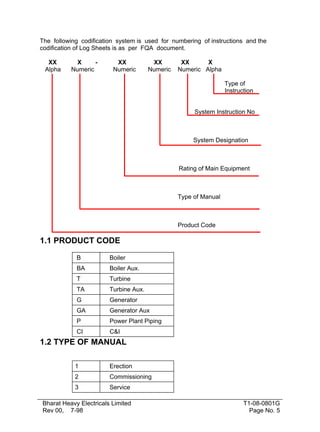
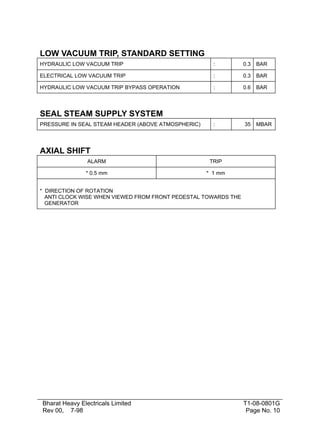
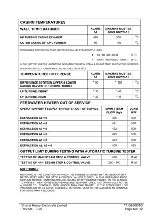
This document provides technical data for the erection of a 500 MW steam turbine from KWU design. It includes specifications for the turbine construction including cylinders, valves, speeds, pressures, temperatures, and limitations. Key details include it being a three cylinder reheat condensing turbine with 17 reaction stages in the high pressure cylinder and 12 reaction stages per flow in the double flow intermediate pressure cylinder. The rated steam conditions and permissible operating values are also provided.
2. FOREWORD
I am glad that Power Sector - Technical Services ( Head Quarters),
Noida has brought out this erection manual of 500 MW steam
turbine (KWU design) being produced by BHEL. This manual lays
emphasis on site optimisation techniques which aims at uniform
erection practices, improvement in quality, reduction in time cycle
and saving in cost.
I am sure, this manual will form the basis for site erection activities
so that the organisation can derive
full benefit out of this. It is
needless to emphasize that upgrading of technology is a continuous
process and we have to review our methods of working and make
suitable changes, wherever required.
New Delhi
Bharat Heavy Electricals Limited
Rev 00, 7-98
(K P Mathur)
Executive Director
(PEM & TS)
T1-08-0801G
Page No. 2
3. PREFACE
The Erection Manual for 500 MW Steam Turbine (KWU design)
manufactured by BHEL
for Thermal Power Stations has been
prepared by a team of BHEL engineers having long experience in
Erection & Commissioning, Design, Quality control of steam turbines.
This dedicated team has been drawn from regional erection group,
designed department of manufacturing units, PS-Q & TS-HQ,
Noida.
The manual carries general description of steam turbine, erection
procedure, special instruction, general instructions, and various other
technical instructions with an intention to establish an uniform
approach for erection of steam turbine.
The Erection Manual provides broad based guide line for erection of
steam turbine.
Product standard, technical circulars & BHEL
drawings for the specific project will precede the instructions and
guidelines furnished in this manual. Project specific document will be
generated by region concerned. This document is generated as a
standard Erection Manual for 500 MW fixed pedestal type steam
turbine with spring loaded foundation.
The work done by TASK FORCE is commendable. Feed-back and
suggestions are welcome for the improvement of this Erection
Manual to bringing down the cycle time with quality.
BHEL reserves the right to suggest alternative
necessity arises at site due to local site conditions .
NOIDA
SNO
DESCRIPTION
Bharat Heavy Electricals Limited
Rev 00, 7-98
procedure
if
(BABOO RAM)
GENERAL MANAGER(TS&Q)
INSTRUCTION NO
T1-08-0801G
Page No. 3
4. 1
TECHNICAL DATA
T 1- 08-0101G
2
INSTRUCTION FOR HANDLING AND
STORAGE OF TURBINE
T 1-08-0202G
3
ERECTION SEQUENCE
T 1-08-0303G
4
ERECTION PROCEDURE
T 1-08-0404G
5
GROUTING PROCEDURE
T 1- 08-0505G
6
ASSEMBLY OF IP MODULE AT SITE
T 1-08-0606G
7
SEALING AND ANTISEIZING COMPOUNDS
T 1-08-0707G
8
CRITICAL ACTIVITIES
T 1-08-0808G
9
SPRING LOADED FOUNDATION
T 1- 08-0909G
10
ERECTION OF PIPING
T 1-08-1010G
11
SPECIFICATION FOR GAS HEATING DEVICE
T 1-08-1111G
12
SPECIFICATION FOR BREECH NUT HEATING
DEVICE
T 1-08-1212G
13
SPECIFICATION FOR THERMAL INSULATION
T1-08-1313 G
Bharat Heavy Electricals Limited
Rev 00, 7-98
T1-08-0801G
Page No. 4
5. The following codification system is used for numbering of instructions and the
codification of Log Sheets is as per FQA document.
XX
Alpha
X
Numeric
XX
Numeric
XX
Numeric
XX
X
Numeric Alpha
Type of
Instruction
System Instruction No
System Designation
Rating of Main Equipment
Type of Manual
Product Code
1.1 PRODUCT CODE
B
Boiler
BA
Boiler Aux.
T
Turbine
TA
Turbine Aux.
G
Generator
GA
Generator Aux
P
Power Plant Piping
CI
C&I
1.2 TYPE OF MANUAL
1
Erection
2
Commissioning
3
Service
Bharat Heavy Electricals Limited
Rev 00, 7-98
T1-08-0801G
Page No. 5
7. 1.4 SYSTEM DESIGNATION
SNO
DESCRIPTION
1.
TECHNICAL DATA
2.
INSTRUCTION FOR HANDLING AND STORAGE
OF TURBINE
3.
ERECTION SEQUENCE
4.
ERECTION PROCEDURE
5.
GROUTING PROCEDURE
6.
ASSEMBLY OF IP MODULE AT SITE
7.
SEALING AND ANTISEIZING COMPOUNDS
8.
CRITICAL ACTIVITIES
9.
SPRING LOADED FOUNDATION
10.
ERECTION OF PIPING
11.
SPECIFICATION FOR GAS HEATING DEVICE
12.
SPECIFICATION FOR BREECH NUT HEATING
DEVICE
13.
SPECIFICATION FOR THERMAL INSULATION
1.5 TYPE OF INSTRUCTION
G
General
T
Technical
L
Log Sheet
C
Check List
Bharat Heavy Electricals Limited
Rev 00, 7-98
T1-08-0801G
Page No. 7
8. LOAD
500 MW
RATED
524.2
MAX. UNDER VALVE WIDE OPEN (VWO) CONDITION
CONSTRUCTION
500 MW
THREE CYLINDER REHEAT CONDENSING TURBINE
SINGLE FLOW HP TURBINE WITH 17 REACTION STAGES
TYPE
H30-100-2
DOUBLE FLOW IP TURBINE WITH 12 REACTION STAGES PER
FLOW
TYPE
M30-63
DOUBLE FLOW LP TURBINE WITH 6 REACTION STAGES PER
FLOW
TYPE
N30-2X10
2 MAIN STOP AND CONTROL VALVES
TYPE
EV320-1
2 REHEAT STOP AND CONTROL VALVES
TYPE
IV560
MAKE
DN-800
BHEL,TIRUCHY
1 SWING CHECK VALVE IN COLD REHEAT LINE
DN-320
2 BYPASS STOP AND CONTROL VALVES
EXTRACTION SWING CHECK VALVES :
EXTRACTION-1
EXTRACTION-2
: 1 SWING CHECK VALVE WITH ACTUATOR
EXTRACTION-3
: 1 SWING CHECK VALVE WITH ACTUATOR
&
1 SWING CHECK VALVE WITHOUT
ACTUATOR
EXTRACTION-4.1
: 2 SWING CHECK VALVE WITH ACTUATOR
EXTRACTION-4.2
: 2 SWING CHECK VALVE WITH ACTUATOR
EXTRACTION-5
: 1 SWING CHECK VALVE WITH ACTUATOR
&
-
: NO VALVE
MAKE
DN-800
BHEL,TIRUCHY
MAKE
DN-500
BHEL,TIRUCHY
MAKE
DN-500
BHEL,TIRUCHY
MAKE
DN-500
BHEL,TIRUCHY
MAKE
DN-400
BHEL,TIRUCHY
1 SWING CHECK VALVE WITHOUT ACTUATOR
EXTRACTION-6
: NO VALVE
SPEED
RATED SPEED
Bharat Heavy Electricals Limited
Rev 00, 7-98
50.0 /S
T1-08-0801G
Page No. 8
9. SPEED LIMITATION IN LOAD & STATION AUX. LOAD
OPERATION
MAX. SPEED, NO TIME LIMITATION
MIN. SPEED, NO TIME LIMITATION
:
:
524.2
51.5 /S
47.5 /S
PERMISSIBLE FOR A MAXIMUM OF 2 HRS. DURING THE LIFE OF
LP BLADING
SPEED
BELOW
SPEED
ABOVE
:
:
47.5 /S
51.5 TO 60 /S
SPEED EXECUTION RANGE AT OPERATION WITHOUT LOAD*
:
6.7 TO 47.5 /S
STANDARD OVER SPEED TRIP SETTING
:
MAX. 55.5 /s
* THIS SPEED RANGE SHOULD BE PASSED THROUGH IN ONE
SMOOTH OPERATION TO AVOID ENDANGERING THE
BLADES DUE TO RESONANCE
STEAM PRESSURES
RATED*
LONG TIME
OPERATION
SHORT TIME
OPERATION
INITIAL STEAM
166.7
166.7
20.7
BAR
BEFORE 1st HP DRUM STAGE
154.4
163.4
169.9
BAR
HP CYLINDER EXHAUST
44.9
52.0
57.4**
BAR
IP CYLINDER STOP VALVE INLET
40.3
46.7
55.2**
BAR
EXTRACTION 6
44.9
52.0
57.4
BAR
EXTRACTION 5
17.5
22.2
22.2
BAR
EXTRACTION 4
7.2
8.7
8.7
BAR
EXTRACTION 3
2.58
3.2
3.2
BAR
EXTRACTION 2
1.329
1.66
1.66
BAR
EXTRACTION 1
0.257
0.41
0.41
BAR
LP CYLINDER EXHAUST
0.1013
0.3
0.3
BAR
* THESE VALUES CORRESPOND TO 500 MW LOAD WITH 3% MAKE-UP AND 0.1013 BAR BACK
PRESSURE WITH ALL HEATERS IN SERVICE AND RATED STEAM CONDITIONS.
** THE SAFETY VALVES MUST BE SET SO THAT THESE SHORT TIME VALUES ARE NOT EXCEEDED.
LONG TIME OPERATION : UPPER LIMIT VALUE, PERMISSIBLE WITHOUT TIME LIMIT.
SHORT TIME OPERATION : PERMISSIBLE MOMENTARY VALUE. THE AGGREGATE DURATION OF
SUCH SWINGS MUST NOT EXCEED 12 HOURS IN ANY ONE YEAR.
ALL PRESSURES ARE ABSOLUTE PRESSURES
Bharat Heavy Electricals Limited
Rev 00, 7-98
T1-08-0801G
Page No. 9
10. LOW VACUUM TRIP, STANDARD SETTING
HYDRAULIC LOW VACUUM TRIP
:
0.3
BAR
ELECTRICAL LOW VACUUM TRIP
:
0.3
BAR
HYDRAULIC LOW VACUUM TRIP BYPASS OPERATION
:
0.6
BAR
:
35
MBAR
SEAL STEAM SUPPLY SYSTEM
PRESSURE IN SEAL STEAM HEADER (ABOVE ATMOSPHERIC)
AXIAL SHIFT
ALARM
TRIP
* 0.5 mm
* 1 mm
* DIRECTION OF ROTATION
ANTI CLOCK WISE WHEN VIEWED FROM FRONT PEDESTAL TOWARDS THE
GENERATOR
Bharat Heavy Electricals Limited
Rev 00, 7-98
T1-08-0801G
Page No. 10
11. STEAM TEMPERATURES
RATED
VAL.
ANNUAL
MEAN
VALUE
LONG TIME
VALUE
(WITHIN
ANNUAL
MEAN
VAL.)
400 h
PER
ANNUM
80 h PER
ANNUM
MAX. 15
MIN IN
INDIVIDUA
L CASE
INITIAL STEAM
536.0
546.O
552.O
566.0
O
IP CYLINDER STOP VALVE INLET
536.0
546.3
552.0
566.0
O
RATED
VALVE *
LONG
TIME
OPERATI
ON
80 h PER
ANNUM
MAX. 15
MIN IN
INDIVIDU
AL CASE
IN
SPECIAL
CASES
AT NO
LOAD
HP CYLINDER EXHAUST
340.0
360.0
440.0
500.0**
O
EXTRACTION 6
340.0
360.0
440.0
500.0**
O
EXTRACTION 5
413.9
421.9
459.9
O
EXTRACTION 4
292.1
304.1
346.4
O
EXTRACTION 3
187.3
195.3
242.3
O
EXTRACTION 2
128.3
139.3
184.3
O
EXTRACTION 1
66.5
86.5
136.5
O
LP CYLINDER EXHAUST
46.1
70.0
70.0
O
C
C
C
C
C
C
C
C
C
C
LONG TIME OPERATION : UPPER LIMIT VALUE, PERMISSIBLE WITHOUT TIME
LIMIT.
*
THESE VALUES CORRESPOND TO 500 MW LOAD WITH 3% MAKE-UP AND 0.1013 BAR
BACK PRESSURE WITH ALL HEATERS IN SERVICE AND RATED STEAM
CONDITIONS.
**
ONLY VALID FOR THE NO LOAD PERIOD WITH HIGH REHEAT PRESSURE AFTER
TRIP-OUT FROM FULL LOAD OPERATION. FOR INDIVIDUAL CASE APPROX. 15
MINUTES
THE TURBINE IS IMMEDIATELY RE-LOADED OR THE BOILER IMMEDIATELY
REDUCED TO MINIMUM LOAD IF NO LOAD OPERATION IS MAINTAINED.
Bharat Heavy Electricals Limited
Rev 00, 7-98
T1-08-0801G
Page No. 11
12. CASING TEMPERATURES
ALARM
AT
MACHINE MUST BE
SHUT DOWN AT
HP TURBINE CASING EXHAUST
480
500
O
OUTER CASING OF LP CYLINDER
90
110
O
WALL TEMPERATURES
C
C
PERMISSIBLE DIFFERENTIAL TEMP. BETWEEN PARALLEL STEAM SUPPLY LINES :
O
•
NO TIME LIMITATION
•
SHORT TIME PERIOD (15 MIN.) : 28 C
: 17 C
O
IN THE HOTTEST LINE THE LIMITATIONS INDICATED FOR INITIAL STEAM & REHEAT TEMP. MUST NOT BE EXCEEDED.
O
SPRAY WATER TO LP TURBINE MUST BE SWITCHED ON AT 90 C.
ALARM
AT
MACHINE MUST BE
SHUT DOWN AT
DIFFERENCE BETWEEN UPPER & LOWER
CASING HALVES HP TURBINE. MIDDLE
* 90
* 100
O
LP TURBINE. FRONT
* 30
* 45
O
LP TURBINE. REAR
* 30
* 45
O
TEMPERATURES DIFFERENCE
C
C
C
FEEDWATER HEATER OUT OF SERVICE
OPERATION WITH FEEDWATER HEATER OUT OF SERVICE
MAIN STEAM
FLOW Kg/s
LOAD
MW
EXTRACTION A6 = 0
395
500
EXTRACTION A5 = 0
421
500
EXTRACTION A3 = 0
423
500
EXTRACTION A2 = 0
425
500
EXTRACTION A1 = 0
423
500
EXTRACTION A6, A5 = 0
400
525
OUTPUT LIMIT DURING TESTING WITH AUTOMATIC TURBINE TESTER
TESTING OF MAIN STEAM STOP & CONTROL VALVE
400
MW
TESTING OF HRH STEAM STOP & CONTROL VALVE
200 - 500
MW
MOTORING :
MOTORING IS THE CONDITION IN WHICH THE TURBINE IS DRIVEN BY THE GENERATOR AT
RATED SPEED WITH THE STOP & CONTROL VALVES CLOSED. IN THIS OPERATING MODE,
CERTAIN TURBINE COMPONENTS ARE HEATED UP BY WINDAGE POWER IN THE BLADING.
TO PREVENT HEAT-UP BEYOND PERMISSIBLE TEMPERATURES, MOTORING MUST NOT BE
ALLOWED TO CONTINUE FOR LONGER THAN ONE MINUTE. IF THE CONDENSER LOW
VACUUM LIMIT OF 0.3 BAR IS EXCEEDED, MOTORING MUST NOT BE ALLOWED TO CONTINUE
FOR MORE THAN 4 SECONDS.
Bharat Heavy Electricals Limited
Rev 00, 7-98
T1-08-0801G
Page No. 12
13. BEARING TEMPERATURES
ALARM
AT
MACHINE MUST BE
SHUT DOWN AT
OPERATION TEMPERATURE BELOW 75 OC
90
120
O
OPERATION TEMPERATURE 75 TO 85 OC
100
120
O
OPERATION TEMPERATURE 85 TO 90OC
110
120
O
OPERATION TEMPERATURE ABOVE 90OC
115
120
O
C
C
C
C
VIBRATION
ABSOLUTE BEARING
HOUSING VIBRATION
ABSOLUTE SHAFT
VIBRATION
30 µ m ABOVE
NORMAL LEVEL*
STANDARD ALARM SETTING
µm
MAXIMUM ALARM SETTING
35
120
µm
LIMIT VALUE FOR TRIPPING
45
200
µm
* THE NORMAL LEVEL IS REPRODUCIBLE VIBRATIONAL BEHAVIOUR TYPICAL FOR THE MACHINE AND
DEPENDENT ON THE OPERATING CONDITIONS, VIBRATION READINGS INDICATED IN CONTROL
ROOM ARE HALF PEAK. THE ABOVE VALUES ARE ALSO GIVEN IN HALF PEAK.
WEIGHTS
HP TURBINE, COMPLETELY ASSEMBLED
:
94.6
T
IP TURBINE. TOP HALF OUTER CASING
:
25.7
T
IP TURBINE, TOP HALF INNER CASING, COMPLETE WITH BLADING
:
15.5
T
LP TURBINE. TOP HALF OUTER CASING COMPLETE
:
42.6
T
LP CYLINDER, TOP HALF OUTER SHELL OF INNER CASING, COMPLETE
WITH BLADING, STATIONARY BLADE CARRIERS & DIFFUSER
:
38.5
T
HP TURBINE ROTOR, COMPLETE WITH BLADING
:
16.3
T
IP TURBINE ROTOR, COMPLETE WITH BLADING
:
23.1
T
LP TURBINE ROTOR, COMPLETE WITH BLADING
:
85.8
T
MAIN STOP & CONTROL VALVE, COMPLETE WITH SERVO MOTORS,
WITHOUT BEND & PIPE SECTION
:
20.9
T
REHEAT STOP & CONTROL VALVE, COMPLETE WITH SERVO
MOTORS, WITHOUT BEND & PIPE SECTION
:
32.2
T
ALL WEIGHTS HAVE BEEN CALCULATED WITH SAFETY ALLOWANCES. SLINGS
CHOSEN MUST PROVIDE SUFFICIENT SECURITY.
Bharat Heavy Electricals Limited
Rev 00, 7-98
T1-08-0801G
Page No. 13
14. OIL SUPPLY
MAIN OIL TANK, RATED CAPACITY
:
25/40
Cu . M
Ist OIL FILLING (ESTIMATED)
:
47.5
Cu . M
FLUSHING OIL QUANTITY (ESTIMATED)
:
28.5
Cu . M
OIL COOLER FOR OPERATION, NUMBER
:
1
NO.
OIL COOLER FOR RESERVE, NUMBER
:
I
NO.
OIL TEMP. AT COOLER OUTLET, UNIT IN OPERATION
MIN.
NORMAL
MAX.
:
:
:
38
45
47
MAX.
:
75
O
NORMAL
MAX.
:
:
20
25
O
OIL TEMP. AT COOLER OUTLET, UNIT SHUT DOWN
TEMP. RISE OF OIL IN BEARINGS
O
C
C
C
ESTIMATED OIL REQUIREMENTS OF BEARINGS :
BEARING 1(HP TURBINE, FRONT PEDESTAL)
:
0.8
dm3/S
BEARING 2
:
15.4
dm3/S
BEARING 3
:
4.1
dm3/S
BEARING 4
:
8.6
dm3/S
GENERATOR FRONT BEARING
:
7.92
dm3/S
GENERATOR REAR BEARING
:
7.92
dm3/S
EXCITER BEARING
:
0.70
dm3/S
1 DUPLEX OIL FILTER FOR BEARING OIL (FULL FLOW)
:
200
mm
DUPLEX OIL FILTER . TYPE - 2.62.9. SIZE 355/750. MAKE
:
BOLL & KIRCH
FILTRATION PARTICLE SIZE OF DUPLEX FILTER ELEMENT
:
37
µm
FILTRATION PARTICLE SIZE OF MAIN OIL TANK FILTER
ELEMENT
:
250
µm
SAFETY VALVE IN JACKING OIL SYSTEM, SETTING
MAX.
:
200
BAR
PRESSURE LIMITING VALVE IN JACKING OIL SYSTEM,
SETTING
:
100
BAR
1 DUPLEX OIL FILTER FOR JACKING OIL
:
25
mm
FILTRATION PARTICLE SIZE OF JACKING OIL FILTER
:
37
µm
Bharat Heavy Electricals Limited
Rev 00, 7-98
T1-08-0801G
Page No. 14
15. OIL PUMPS
JACKING
OIL PUMP
MAIN OIL
PUMP
AUXILIARY
OIL PUMP
DC
EMERGENCY
OIL PUMP
1
2
1
BHEL
KSB
KSB
TUSHAKO
97.22 dm3/S
ETA-15050VVL
ETA-10033VVL
SDF80
CAPACITY
(RATED)
75
89.25
30
1.53
dm3/s
DISCHARGE
PRESSURE
(GAUGE)
8.6
6.2
2.3
178
BAR
SPEED
50
24.75
24.3
49.42
/s
DRIVE
TURBINE
AC MOTOR
DC MOTOR
QUANTITY
MAKER
TYPE
Bharat Heavy Electricals Limited
Rev 00, 7-98
AC : 2
DC : 1
AC
MOTOR
DC
MOTOR
T1-08-0801G
Page No. 15
16. CONTROL FLUID SUPPLY
CONTROL FLUID TANK, RATED CAPACITY
:
10/16
Cu . M
Ist FLUID FILLING (ESTIMATED)
:
15
Cu . M
FLUSHING FLUID QUANTITY (ESTIMATED)
:
10
Cu . M
CONTROL FLUID COOLER FOR OPERATION, NUMBER
:
1
NO.
CONTROL FLUID COOLER FOR RESERVE, NUMBER
:
I
NO.
CONTROL FLUID MAINTENANCE EQUIPMENT :
GEAR PUMP
MANUFACTURER
TYPE
:
:
STEIMEL
BGK 2-24R
FLUID FLOW
:
0.28
dm3/S
GAUGE PRESSURE
:
3.06
at
SPEED
:
25
S-1
MOTOR POWER
:
0.75
KW
2 EARTH FILTERS
MANUFACTURER
TYPE
:
:
:
EARTH FILLING MESH
1 FINE MESH FILTER
MANUFACTURER
TYPE
:
:
FILTRATION PARTICLE SIZE
:
FILTER MATERIAL
:
ROTRING
PYG5-350
140
Kg
ROTRING
S-1800-14-TUY
µm
3-5
COTTON
CONTROL FLUID SUPPLY SYSTEM
A FIRE RESISTANT FLUID IS USED FOR THE CONTROL SYSTEM
SCOPE
The document covers all steam turbine components and provides the handling,
inspection and storage instructions for large steam turbine components at site.
A strict adherence to these instructions is necessary to avoid damages during
handling and storage at site.
Bharat Heavy Electricals Limited
Rev 00, 7-98
T1-08-0801G
Page No. 16
17. HANDLING OF EQUIPMENT :
In any kind of rigging work it is necessary to strictly observe the safety precautions,
since even the slightest negligence and non observance of the rules may result
in accidents, which may cause damage to equipment or injury to men.
The site for the rigging work involving lifting and conveying of loads should be well
lighted. The loads must not be lifted unless the crane operator can see clearly
the signals given by the rigger.
The positions where the slings are to be put, are marked on the packages and on
the drawings. While lifting/handling these packages/equipment, the slings
should only be put at the proper places.
The slings of the proper sizes and lengths should only be used for handling the
equipment/packages. The angle between the two arms of the sling at the
crane hook should be small (depending upon the dia of the sling) so as to have
proper loading of the sling.
The turbine rotors and cylinder covers (in assembled condition are lifted by the
use of special lifting devices supplied by BHEL. The use of these lifting
devices facilitates correct slinging and maintain horizontal position of the
components. These devices, after use, should be properly stored and
conserved so as to ensure that they do not get damaged during storage.
Before using them, they should be thoroughly inspected.
The work related to handling of the loads (packages or equipment) by crane or by
other hoisting mechanism should be entrusted to trained riggers only. If
the rigger/operator is not sure of the weight of the item/package (load) to
be handled, he must ask for the required information before handling the
equipment.
The rigger and the crane operator should see that the hook and the ropes of the
crane occupy vertical position, before hoisting the load. Dragging of the load
by slanting ropes is not allowed. The center of gravity of the load should be
aligned with the vertical axis of the crane hook.
The eye bolts, 'D' shackles, turn buckles, and wire ropes of suitable sizes should
only be used for handling of the equipment. Before using, they should be
thoroughly inspected to their full threads, so as to avoid any chance of
slipping then the load comes on them.
Before giving a signal to lift the load, the rigger must check and ensure that there are
no loose parts or tools on the load, which might fall during lifting. Then the load
must be lifted 100 or 200 mm high for checking the uniformity
of sling
tensioning and reliability of lashing. If it is necessary to rearrange the sling
lengths, the load must be lowered and then the slings rearranged.
Before horizontal conveyance of the load the rigger must see that the load has been
lifted to a height at least 0.5 M above the tallest object, on the path of the load.
Bharat Heavy Electricals Limited
Rev 00, 7-98
T1-08-0801G
Page No. 17
18. While the load is being conveyed, the rigger must accompany it and see
that it is not moved above any person. Prior to lowering the load the rigger
should examine the ground on which the load will be, lowered and make sure
that these is no risk of falling or slipping of the load.
If any one of the personnel present during lifting or lowering of the load detects some
defect of the crane or sling of notices some conditions jeopardizing the lifting or
lowering operation, he must give a signal for emergency grounding of the
package or components.
Smooth lifting and transportation of equipment must be ensured. Shocks and jerks
should be avoided.
All
lifting devices, slings must be
inspected and tested.
properly
conserved after
use and periodically
In the turbines having diaphragms, it is prohibited to handle diaphragms by putting
slings in between the blades. For handling the welded diaphragms, special
lifting devices is supplied by BHEL and the cast diaphragms are handled
by putting the eye bolts, for which the provision of threads holes have been
made in the diaphragms.
While handling the bearings, it is prohibited to put the sling across the rabbit surface of
the bearings. Threaded holes have been provided; in which the eye bolts have
to be put for handling of the bearings.
While handling the cylinders, it must be ensured that the slings or any other material
does not get rubbed at their horizontal and vertical parting planes or at any
other machined surface.
The handling of the long components such as longitudinal girder, endwall etc. should
be done with extra care. When they are placed on the floor, in addition to the
end supports, few extra supports at the intermediate positions must be provided.
While handling LP rotor with free standing blades, care must be taken to ensure that no
force is exerted on the free standing blades to avoid collapsing of clamping
pieces under blade root.
MARKINGS ON PACKING CASES
Various symbols are marked on the packing cases as per 0456.001 to facilitate
storage and handling of the crates and protection of equipment inside.
INSPECTION
Before storing the equipment it should be opened for visual examination or the
internal packing, protective coating and condition of the equipment. Any
damage to packing and conservation should be immediately rectified.
It
is necessary to carryout first inspection within three weeks of arrival of the
consignment. Thereafter, all the equipment should be inspected once in every
three months to insure that the conservation is intact. During rainy season, the
inspection should be done once in a month. At any time, if any original
Bharat Heavy Electricals Limited
Rev 00, 7-98
T1-08-0801G
Page No. 18
19. conservation is found damaged, it should be reconserved as per
conservation instructions No. ST 33004.
relevant
While inspecting the packages containing rotors, special care should be taken to check
the journals. In case of slightest sign of pitting on the journals and thrust
collar, immediate steps for rectification should be taken and equipment
reconserved as per relevant conservation instructions.
STORAGE
All steam turbine equipment should be accommodated in the designated place of
storage immediately after arrival at destination. This is very essential particularly
during the rainy season.
Store houses fall into the following categories
TYPE OF
STORE
HOUSE
CONDITIONS
TEMP.
RELATIVE
HUMIDITY
'P'
+50 C
to
500 C
< 70 %
'Q'
upto
500 C
-
Roofed area with walls (of brick /
asbestos/ GI sheet ) around and
cemented / pucca hard floor.
'R'
-
-
Raised platform with shed of asbestos /
GI sheet / water proof tarapaulin.
'S'
-
-
Raised Platform.
Bharat Heavy Electricals Limited
Rev 00, 7-98
ARRANGEMENT
Totally enclosed, rain proof, ventilated
and dry with cemented floor.
T1-08-0801G
Page No. 19
20. The
platforms and store-houses should be built up in conformity with the fire
prevention rules and standards. Complete storage area especially the ‘R’ & ‘S’
catagory must be adequately fenced & protected against theft & pilferage.
These store houses and areas around them should have proper drainage facility for
the sub-soil, surface and rain water. The water should not be allowed to stand
or get accumulated in these areas, especially where the material has been
stored.
Store house should be provided with proper ventilation facilities.
Level should be maintained for all the packages and equipment and should be
uniformly supported to avoid distortion. The long packages should be
supported at intermediate places also, so as to avoid sagging during storage.
Store houses should preferably be equipped with proper lifting devices to ensure
normal handling of equipment.
Small and medium size parts can be kept on shelves with proper identification tags.
Packages upto 5 tones can be placed on upon the other upto 2.5m in height using
required number of wooden spacers 50 mm thick. In doing so, lighter
packages would be laid upon heavier once to avoid any damage to lower
packages.
Articles weighing more than 5 tones should be laid in a single tier.
For heavier components under ‘Q’, the roof/walls may be constructed/fabricated after
placement of the component on cemented/pucca hard floor.
Bharat Heavy Electricals Limited
Rev 00, 7-98
T1-08-0801G
Page No. 20
21. STORAGE OF STEAM TURBINE COMPONENTS
SNO.
DESCRIPTION OF THE COMPONENT
TYPE OF
STORAGE
1.
FOUNDATION BOLT
Q
2.
EMBEDDED PARTS (ADDITIONAL)
R
3.
COMPONENTS OF BASE PLATE ASSLY.
Q
4.
BASE PLATE LP CASING
R
5.
LP OUTER CASIONG
R
6.
LONGITUDINAL GIRDER (LEFT & RIGHT)
R
7.
LP FRONT WALL (TS&GS)
R
8.
LP SHAFT SEALING (FRONT & REAR)
Q
9.
AUXILIARIES OF TURBINE
Q
10.
HP/IP BEARING PEDESTAL
Q
11.
HP/IP BEARING PEDESTAL ASSEMBLY PARTS
Q
12.
IP/LP PEDESTAL ASSEMBLY
Q
13.
LP/GEN. PEDESTAL
Q
14.
BEARING PEDESTAL PARTS
Q
15.
FRONT BEARING PEDESTAL
Q
16.
LIFTING BEAM
R
17.
LP CASING EXTRACTION A1
R
18.
LP EXTRACTION A2
R
19.
LP EXTRACTION A3
R
20.
LP EXTRACTION PIPE SHEATHING
R
21.
INNER GUIDE PLATE DIFFUSER
R
22.
DIFFUSER (UPPER & LOWER HALVES)
R
23.
LP INNER-OUTER CASING (VH)
Q
24.
LP INNER CASING ASSEMBLY (LH & VH)
Q
25.
HEATING DEVICE
Q
26.
LP CASING ASSEMBLY
Q
27.
LP INNER CASING ASSEMBLY (FASTENER)
Q
28.
INNER GUIDE PLATE DIFFUSER (GS)
R
29.
LP ROTOR
Q
30.
IP TURBINE
Q
Bharat Heavy Electricals Limited
Rev 00, 7-98
T1-08-0801G
Page No. 21
22. 31.
IP TURBINE PARTS
Q
32.
IP INLET PIPES
Q
33.
HP TURBINE
Q
34.
HP INLET ASSEMBLY
Q
35.
HP EXHAUST ELBOW
Q
36.
HPT RELATED PARTS
Q
37.
FRAME FOR SUSPENSION (ESV)
R
38.
SUSPENSION OF VALVE (ESV)
Q
39.
ESV & CV CASING WITH VALVE
Q
40.
ESV SERVOMOTORS WITH LIMIT SWITCH
Q
41.
HP CONTROL VALVE SERVOMOTORS
Q
42.
SUSPENSION OF VALVE (IV)
Q
43.
IV & CV CASING WITH VALVE
Q
44.
IV SERVOMOTORS WITH LIMIT SWITCH
Q
45.
IP CONTROL VALVE SERVOMOTORS
Q
46.
FRAME FOR SUSPENSION (IV)
R
47.
IV SERVOMOTORS WITH LIMIT SWITCH
Q
48.
STEAM BLOWING & HYD. TEST DEVICE
Q
49.
TOOLS FOR GOVERNING SYSTEM
Q
50.
SUSPENSION OF LPB VALVE
Q
51.
WATER INJECTION VALVES
Q
52.
CHEST LPB WITH STOP & CONTROL VALVE
q
53.
LPB STOP VALVE SERVOMOTOR
Q
54.
LPB CONTROL VALVES SERVOMOTORS
Q
55.
INJR. FOR SUCTION PIPE NB 350
R
56.
INJR. FOR SUCTION PIPE NB 300
R
57.
MAIN OIL TANK
R
58.
MAIN OIL TANK & NOZZLE ASSEMBLY
R
59.
OIL STRAINER
Q
60.
LEVEL MONITOR INSTALLATION
Q
61.
INSTRUMENTS
Q
62.
LEAKAGE / DIRTY FLUID TANK
R
63.
VARIABLE ORIFICES & THROTTLE
Q
Bharat Heavy Electricals Limited
Rev 00, 7-98
T1-08-0801G
Page No. 22
23. 64.
CONTROL FLUID TANK
R
65.
CONTROL FLUID TANK NOZZLE ARRANGEMENT
R
66.
EXPANSION TANK
R
67.
FILTER & PR. DAMPING DEVICES
Q
68.
CROSS AROUND PIPE
R
69.
SUPPORT FOR CAP
R
70.
CHANGE OVER VALVE
R
71.
RATING & MONOGRAM PLATES
Q
72.
OIL STRIPER
R
73.
HOUSING FOR HRH STEAM STRAINER
R
74.
HOUSING FOR MAIN STEAM STRAINER
R
75.
MS & HRH STR.HSG GASKET
Q
76.
STEAM STRAINER MS
Q
77.
STEAM STRAINER HRH
Q
78.
COMPENSATOR
Q
79.
TURBINE CONTROL LPB / SUPPLY RACK
Q
80.
TEMPERATURE & PRESSURE CONNECTIONS
Q
81.
PR. TRANSMITTERS BAR. PROBES THERMOCOUPLES
Q
82.
TRANSMITTERS & JUNCTION BOXES
Q
Bharat Heavy Electricals Limited
Rev 00, 7-98
T1-08-0801G
Page No. 23
24. STORAGE & PRESERVATION OF COMPONENTS OF
TURBOGENERATOR, EXCITER AND SYSTEMS
SNO.
1.
2.
3.
4.
5.
6.
7.
8.
9.
10.
11.
12.
13.
14.
15.
16.
17.
18.
19.
20.
21.
22.
23.
24.
25.
26.
27.
28.
29.
30.
31.
32.
DESCRIPTION OF THE COMPONENT
EMBEDDED PARTS
FOUNDATION PARTS
WOUND STATOR WITH GAS COOLERS
TURNION FOOT PLATES
ROTOR
ASSEMBLY OF PIPE CONTROL FOR GAS COOLERS
END SHIELDS
FAN SHIELD, GEN VVIEW HEADER ASSEMBLY
TERMINAL BUSHING AND HEADER ASSEMBLY
BEARING WITH BRUSH GEAR
SEAL BODY
TEMP. CONNECTION
CASING FOR TURNIONS
ERECTION MATERIALS
ERECTION DEVICES
SHAFT SEALS
SEAL RINGS
ADOPTING RING
AUXILIARY BEARING
CENTRIFUGAL FAN
CARBON DIOXIDE VAPOURISER
FILTER O.C.P.
EXPANSION TANK
OIL SEPARATOR
PRE CHAMBER
S.O.S.T.
SEAL OIL UNIT
HYDROGEN DISTRIBUTION
CARBON DIOXIDE DISTRIBUTION
VALVES FOR AUXILIARY SYSTEMS
GAS UNITS
FLEXIBLE LEADS
TYPE OF
STORAGE
R
R
Q
Q
Q
R
Q
R
Q
Q
Q
Q
R
Q
R
Q
Q
Q
Q
Q
Q
Q
R
R
R
R
Q
R
R
P
Q
Q
STORAGE & PRESERVATION OF COMPONENTS OF
HEAT EXCHANGERS
SNO.
DESCRIPTION OF THE COMPONENT
TYPE OF
STORAGE
PRODUCT : CONDENSER
Bharat Heavy Electricals Limited
Rev 00, 7-98
T1-08-0801G
Page No. 24
25. 1.
2.
3.
4.
5.
6.
7.
8.
9.
10.
11.
12.
13.
14.
15.
16.
17.
18.
19.
BOTTOM PLATE
LOWER DOM WALL
SIDE WALL
WATER CHAMBER
UPPER DOM WALL
STIFFENING PIPES
STIFFENING RODS
TUBE SUPPORT PLATE
WATER BOX
AIR EXTRACTION PIPING
HOTWELL
SPRING ELEMENTS
LOOSE ITEMS
INSTRUMENTS
CONDENSER TUBES (STAINLESS STEEL)
CONDENSER TUBES (NON-FERROUS)
VACUUM PUMP
EJECTOR
AIR MEASURING DEVICE
S
S
S
Q
S
S
S
R
R
R
S
R
Q
Q
R
Q
Q
R
Q
PRODUCT : HEATER
1.
2.
3.
4.
5.
1.
2.
3.
4.
5.
6.
GLAND STEAM CONDENSER
STAND PIPE
INSTRUMENTS
DRAIN COOLER
L.P.HEATERS
PRODUCT : COOLER
OIL COOLER
CONTROL FLUID COOLER
STATOR WATER COOLER
HYDROGEN COOLER
EXCITER AIR COOLER
INSTRUMENTS / LOOSE ITEM
Bharat Heavy Electricals Limited
Rev 00, 7-98
R
Q
Q
R
R
R
R
R
Q
Q
Q
T1-08-0801G
Page No. 25
27. ERECTION SEQUENCE
(For 500 MW Fixed pedestal type Turbine with spring loaded foundation)
1. Cleaning and checking of Turbine and Generator foundations as per the transverse
and longitudinal axis including their elevation.
2. Prepare and install LP base plates, HP front pedestal, HP rear pedestal, LP front
pedestal, LP rear pedestal along with their anchor bolts and anchor plates.
3. Provisionally
align and level all the pedestal and LP base
plates as per the
transverse and longitudinal axis including their elevation.
4. Matching of anchor plates of pedestal and LP base plates to ensure their perfect
seating.
5. Finally align and level HP front, HP rear, LP front and LP rear pedestals along with
LP base plates as per the transverse and longitudinal axis including their elevation
and catenary as per the design.
6. Prepare and install steel bars for LP casing centralising keys in foundation slab as
per the required center line .
7. Weld locating ring of LP front pedestal and steel bars of LP front and LP rear
centralising keys.
8. Prepare shuttering and grouting of the pedestals and LP base plates including
anchor plates of HP rear pedestal.
9. Prepare, install, align/ level both the LP girder along with their carrier plates.
10. Prepare , install and assemble LP front and rear end walls with the LP girders.
11. Level / align LP outer casing lower half as per the transverse and longitudinal axis
of the machine.
12. Install permanent packers of LP outer casing including their radial and axial keys.
13. Prepare and install LP inner outer casing along with gusset plates in position
Bharat Heavy Electricals Limited
Rev 00, 7-98
T1-08-0801G
Page No. 27
28. 14. Align LP inner outer casing lower half and level it. Install LP casing parting plane
platform .
15. Prepare and install LP front and LP rear lower half shaft seals housing and align it
provisionally.
16. Prepare and install LP rotor along with their bellows in position.
17. Align LP rotor radially and axially in position and record free run out of rotor.
18. Record/ Ensure radial and axial clearances of the LP casing including rotor float
including fitting of final axial keys of the LP inner casing .
19. Box up LP inner inner casing and heat tighten the parting plane bolts.
20. Box up LP inner outer casing .
21. Prepare and place HP module in position on temporary packers.
22. Transfer the load of HP rotor on bearings from the transport device and align it
radially and axially.
23. Check free run out of HP rotor on journal and coupling face including its float.
24. Prepare and place IP module in position on temporary packers. (In case IP module
is sent to site in disassembled condition, refer Instruction T1-08-0606G.
25. Loading of IP rear end of the shaft on bearing and removal of transport device.
26. Provisionally align HP , IP and LP rotor .
27. Couple HP / IP rotor on temporary Bolts and align rotor / casing radially and axially.
28. Record/ Ensure IP rotor float by shifting HP casing axially.
29. Conduct Horn drop test of HP casing without any radial and axial keys and pipe
lines.
30. Conduct Horn drop test of IP casing without IP inlet upper half pipe lines.
31. Assembly of breech nut of HP casing and Main Steam Stop & Control valve
assembly.
Bharat Heavy Electricals Limited
Rev 00, 7-98
T1-08-0801G
Page No. 28
29. 32. Erection of Reheat Stop & Control valve assembly.
33. Weld IP inlet upper half pipe and record Horn drop values without radial-axial keys.
34. Alignment of HP/IP/LP rotors and their coupling on temporary bolts including its
couple runout.
35. Swing check of HP rotor on its front end with temporary alternate bolt tightened on
HP/IP coupling .
36. MOP alignment and its doweling.
37. Reaming/honing of HP/IP and LP/IP coupling including fitting of final coupling bolts.
38. Fixing of axial position of shaft and assembly of thrust bearing including its colour
matching.
39. Roll check of HP/IP casing and fixing of radial and axial keys of the casing (Casing
final packers need not to be put at this stage).
40. Assembly of bearings and checking of all clearances including fittings of side pads
of bearing, yoke keys etc.
41. Turbovisory works in all the pedestal i.e. assembly and calibration of thrust bearing
axial
shift, LP rotor expansions pick up, Hall generator and thermocouples of
bearing .
42. Preparations of the bearing for oil flushing.
43. Oil flushing of the machine and normalizing the bearing after oil flushing.
44. Preparation and floating of TG deck as per Instruction No. T1-08-0909G.
45. Decoupling of HP / IP, LP/IP, LP/Gen., Gen./Exciter coupling and rechecking of
alignment/catenary after floating of TG deck spring.
46. Final tightening of HP/IP, IP/LP , LP/Generator and Generator / Exciter coupling
after correcting the alignment including their couple run out and swing check of rotor
on HP Front and exciter rotor.
Bharat Heavy Electricals Limited
Rev 00, 7-98
T1-08-0801G
Page No. 29
30. 47. Checking /Correction of LP shaft seal clearance after floating of TG deck with CW
pump in operation and water in the hot well of condenser upto operating level.
48. Roll check of HP, IP casing in up and down direction only with TG deck in floating
condition and CW pump in operation including water in hot well upto normal level.
49. Assembly of final packers of the HP, IP casing after completing the roll check in up
and down direction.
50. Recording of final Horn drop of HP and IP casing after completing the welding of
HP inlet, HP exhaust , IP inlet and Cross around piping.
51. Preparation and boxing up of LP casing after competing the full Roll check of LP
casing and fitting of final casing packers and radial keys.
52. Barring gear.
Bharat Heavy Electricals Limited
Rev 00, 7-98
T1-08-0801G
Page No. 30
31. CHECKING OF FOUNDATION BEFORE CASTING
Customer to provide, center line and elevation point.
Check positioning of all the inserts and fixed points with respect to center line
in transverse and longitudinal direction as per BHEL Hardwar drawings.
Check elevation of all points.
Check verticality of all the pipe sleeves with the help of plumb.
Ensure proper locking of all the insert and fixed points before grouting.
Ensure leveling on the fixed points of LP girder and LP rear pedestal.
Preserve machined surfaces of all the fixed points against any damages due to
Improper handling.
Ensure proper flatness of the bottom seating plate of all the inserts.
Ensure proper stiffeners in all the vertical and horizontal embedment provided
for various purposes like hangers and supports etc.
Ensure proper cleaning of the area before casting.
Remove all unwanted material.
NOTE: In case of spring loaded TG deck refer Installation Instruction
No. T1-08-0909G prior to positioning of inserts etc.
CHECKS DURING CASTING/POURING OF CONCRETE
Casting of foundationTG deck should be carried out immediately after
inspection of the foundationTG deck i.e. within 3-4 days after final
inspection to avoid any disturbance to the inserts and fixed point.
Ensure no disturbance to the insert etc. during pouring of concrete while
vibrators are used.
Bharat Heavy Electricals Limited
Rev 00, 7-98
T1-08-0801G
Page No. 31
32. About 15-20 mm extra concrete may be left on top on all the pedestals and LP
base plate area for chipping/cleaning purpose at a later date.
Close all the pipe sleeve from top to avoid entry of concrete inside. Alternately
the pipe sleeve should be filled with sand.
CHECKING OF FOUNDATION AFTER CASTING
Clean complete foundation and remove all shuttering etc.
Ensure there is no loose concrete layer in the region where the pedestal and
base plates are to be laid. No repair should be done in this region without
consulting the turbine erection engineer.
Cover all the opening before checking any dimensional measurement to
avoid any accident.
Establish a suitable longitudinal axis considering the fixed point of the LP rear
pedestal and various pipe sleeves / inserts.
Establish a transverse axis as 90 degree with the help of the odolite.
Measure pitching/elevation of all the inserts and fixed points.
Measure elevation of all foundation on different pedestal and LP base plate area.
Check level of LP rear pedestal fixed points and if required correction may
be carried out.
PREPARATION OF FOUNDATION FOR PLACEMENT OF
PEDESTALS AND BASE PLATES:
Foundation are to be cleaned and loose concrete are to be chipped off.
Maintain elevation of foundation to ensure correct thickness of non-shrink
grout.
A reference point for elevation in respect of machine center line (equivalent to LP
rear pedestal) is to be maintained at a proper place. This point is to be
preserved with proper protection. For making reference point a one side
ground plate of about 200 x300 x20 mm may be used. This may be
welded on a I-beam near Generator. The ground position of the plate is
to be kept on top side and all elevation are to be transferred from this
point with the help of water level jar. A correct elevation reading is to
be punched on this plate. This reference point is to be used only during the
turbine erection period.
Clean and deburr piping sleeves of the foundation on ID/OD
of the pipe.
Ensure all corners of the foundation remains perfect during chipping of extra
concrete of foundation.
Bharat Heavy Electricals Limited
Rev 00, 7-98
T1-08-0801G
Page No. 32
33. PLACEMENT OF PEDESTALS
Open and clean the pedestal.
Ensure there is no paint/oil on bottom face of the pedestal sole plate.
Ensure there is no paint on inside surface or the pedestal and if required sand
blasting may be carried out at site.
Ensure correct fitting/clearance of locating rings of LP rear pedestal.
The half bore error of pedestals is punched by manufacturing unit however in
case it is not there, measure and punch half bore error of pedestal in
left/right side of the pedestal. If the error is nil then this may be
punched as zero-zero.
Ensure that the pedestal parting plane is feeler tight after tightening all the
parting plane bolts. If required, colour matching may be carried out but
scraping/cutting is to be done on upper half cover only.
Check proper colour contact of spherical/cylindrical supports of the bearing
with the pedestal.
Bharat Heavy Electricals Limited
Rev 00, 7-98
T1-08-0801G
Page No. 33
34. Check contact between spherical Torus piece of bearing and
spherical/cylindrical seat. In case of any variation in contact no
scraping/cutting to be carried out at site and this may be referred to
manufacturing unit. Also refer T1-08-0808G. Check centering of individual
bearing w.r.t. pedestal seal bores by fixing pianowire on individual
pedestal.
Ensure cleanliness of all pedestal oil lines. Close opening of oil lines of
pedestal to avoid any foreign material entering in these pipe lines during
erection at site.
Weld MOP suction and discharge pipe lines in HP front pedestal as per the
drawing before placement.
Assemble protection sheet in the foundation bolt holes of pedestals.
Assemble anchor bolts along with anchor plate of the pedestals. Ensure that
there is good contact available to the backing plate with the
foundation. If required colour matching/grinding may be carried out to
achieve the contact.
Assemble protection sheet in the anchor bolt hole from bottom side of HP rear
pedestal foundation to avoid entry of grout metal.
Ensure level of both anchor plate of H.P. rear pedestal with 70-90 mm gap for
filling of grouting concrete.
Adjust height of the Anchor Bolts as specified in the drawing.
PLACEMENT OF LP BASE PLATE, OVER THE FOUNDATION :
Clean all the four base plates.
Mark/punch center line on the base plate as per drawing.
Ensure proper cleaning of base plate on bottom side.
Put identification marks on each base plate to avoid any mistake in positioning of
the same.
Do colour matching of all the eight nos. carrier plate on both the faces.
Match LP base plate with the individual carrier plate.
Place all the four base plates in position along with their leveling screws and
foundation bolts.
Provisionally align and level all the four base plates.
Assemble protection sheet in the foundation bolt holes.
Bharat Heavy Electricals Limited
Rev 00, 7-98
T1-08-0801G
Page No. 34
35. ALIGNMENT OF PEDESTALS AND LP BASE PLATES
Provisionally align and level all the four pedestals including LP base plates with
reference to the earlier marked longitudinal and transverse axis. The
elevation reference is to be taken from the already positioned plate for
this purpose.
Align and level LP rear pedestal and set the elevation as per machine center line.
Use piano wire arrangement with micrometer for centering of pedestal bore and
use water level jar for setting of elevation. Use measuring tape to
maintain pitching of the bearing from one pedestal to another. Pedestals
are to be set in level condition on both longitudinal and transverse
direction. Align and level HP front, HP rear and LP front pedestals.
Elevation of the pedestals are to be set as per catenary of the machine
considering the half bore error of the pedestal if any.
Align and level, LP base plates. Elevation of LP base plate is to be kept higher
than the rear pair of LP base plate in line with catenary of rotor.
After alignment of LP rear pedestal weld the locating rings as mentioned in the
drawing.
During welding of locating ring, ensure that there is no movement in the
pedestal in any of the direction.
Bharat Heavy Electricals Limited
Rev 00, 7-98
T1-08-0801G
Page No. 35
36. GROUTING OF PEDESTALS AND LP BASE PLATES
Fill 3 to 8 mm washed Pea-gravel in all the anchor bolts sleeves. These gravel
are necessary to give damping effect to the anchor bolts during operation
of the machine.
Seal anchor bolts holes after filling of gravel to avoid any entry of grout metal.
Medical tape may be used for sealing of these anchor bolt holes.
Clean foundation with compressed air.
Make shuttering of all the pedestal and LP base plates. Use thick polythene
sheet inside the shuttering to give better finish and avoid moisture
absorption by shuttering.
Shuttering should be made with maximum care to avoid any leakage of grout
concrete. All sides of the shuttering are to be sealed either with some
sealing compound or with thick mixture of grout material to avoid leakage
of grout material.
Foundation are to be kept wet for about 6 hrs. before grouting.
Non shrinkage cement duly approved by BHEL is to be used for grouting of the
pedestals and base plate.
Use fresh stock of the grouting material only and check the strength of the
material before use.
During grouting, the mixture has to be poured from one end only and it has to
flow to opposite end to avoid any blockage of air pocket.
Water curing is to be carried out for about 10 days duration.
All anchor bolts are to be stretched minimum after 21 days of grouting.
HP, IP & LP module placement work can be taken up after 24 hours of grouting
of the pedestal and base plates.
For individual pedestal and base plate, grout mixture should be poured in one lot
only.
PLACEMENT OF HP MODULE IN POSITION
Ensure matching of all the four palms of the module where it is resting on the
pedestals.
Ensure matching and parallelity of front and rear key block of the HP casing.
Assemble all four jacking screw of HPC and ensure their free movement.
Clean journals and coupling of the HP rotor.
Record journal dia, coupling hole sizes and spigot dia of HP rotor.
Bharat Heavy Electricals Limited
Rev 00, 7-98
T1-08-0801G
Page No. 36
37. Lift module in level condition and place it in position by keeping it 3 to 5 mm
toward front pedestal side.
During placement of module use temporary packers similar to permanent and
additionally support it by four jacking screws.
Ensure load on all four packers with the help of some additional shims if
required.
Install temporary radial and axial keys of the casing.
Prepare HP rotor for alignment (Ref. section 20 before placing the IP module.
PLACEMENT OF IP MODULE IN POSITION
Ensure matching of all the four palms of the module where it is resting on the
pedestals.
Ensure matching and parallelity of front and rear key block of IP casing.
Assemble all four jacking screws of IP casing and ensure their free
movement. If these jacking screw holes are provided with the bolts
from factory then same are to be removed before placement of module.
Clean IP rotor on both sides including coupling and journal.
Record spigot /recess, journal dia, and coupling hole sizes.
Lift the module in level condition and place the module in position by moving
about 7 to 8 mm towards generator end. Use temporary packers for
placement of module in position and additionally support the module with
jacking screws.
Ensure load on all four packers with the help of some additional shims if
required.
Provisionally align the casing on front and rear pedestal bore. Install temporary
radial and axial keys of the casing with some shims.
Prepare IP rotor for alignment (Ref. section 20).
NOTE: In case IP module is sent to site in disassembled condition, refer
Instruction T1-08-0606G.
ASSEMBLY OF LP MODULE
This assembly can be divided in following sub assemblies:
Bharat Heavy Electricals Limited
Rev 00, 7-98
T1-08-0801G
Page No. 37
38. Assembly of girder and end walls.
Assembly of LP inner inner and LP inner outer casing lower half.
Assembly / welding of LP outer casing.
Before starting assembly of LP casing in position, following works are
also to be completed :
- Positioning and welding of LP casing centering pin of front and rear
side.
- Positioning of key block of LP casing axial keys.
- Positioning of all internal of condenser.
POSITIONING AND WELDING OF LP CASING CENTERING
PIN
Two nos. centering pins are to be located below LP front and LP rear pedestal.
Necessary pipe along with two sq. end plates are already provided in the
foundation to take the radial load of the LP casing:
Plumb the center line from LP front and LP rear pedestal bore on both side
over the square plate of the foundation.
Establish accurate position of the pin and put a punch mark at a required height
and mark a circle and a controlling circle over all the four sq. Plates.
Bharat Heavy Electricals Limited
Rev 00, 7-98
T1-08-0801G
Page No. 38
39. Dia of the circle must be equal to pin dia. A template equivalent to pin dia has
to be made for this purpose with about 20 mm thick plate and a welded
pipe for using as an handle. The template dia must be very accurate and
same may be made on machine.
Make precise hole with gas cutting/grinding to match template on all four
embedded plate. Ensure that the template is fitted with minimum
clearance and hole center are perfect as per marking.
Drill hole of about 10 mm dia on one of square plate of LP front and on one
plate of LP rear for air venting to avoid cracks during welding.
Insert both the pins and carry out the welding as per laid down procedure.
Before welding set correct axial position of the pins.
Insert key block on both the pins and weld their locking ring also. Ensure
proper clearances in key block before welding of its locking ring.
Preheating of 200 degree Celsius or more to be achieved before any welding.
Dye penetrate test on root run and after final welding is to be carried out.
Bharat Heavy Electricals Limited
Rev 00, 7-98
T1-08-0801G
Page No. 39
40. ASSEMBLY OF GIRDER AND END WALL
Colour match side matching flange of girder with the surface plate.
Colour match seating flange of girder where it rests over the LP base plate.
Match and ensure parallality of axial key ways of girder.
Colour match side flanges of end wall.
Match and ensure parallality of key block of end wall.
Place left and right girder with carrier plate, spacer and lubrite packer on LP
base plate.
Provisionally align and level the girders. Set height of the girder equivalent to
machine center line maintaining catenary of the machine with the help of
water level jar arrangement.
Assemble locking plate of the front and rear end wall to facilitate its assembly
with the girders.
Assemble front and rear end wall with the girders and ensure perfect parting
plane level during tightening.
Align, level LP outer casing and ensure contact of packers by colour
matching/machining of spacer height.
Install LP casing radial and axial keys.
Assemble inner outer casing axial key blocks on left and right side of girder
and dowel them.
Lock with tack welding all the vertical joint bolts.
Put a seal weld run between girder and end wall joint all around except on top
face.
Weld girder and end wall parting plane joint with argon welding. Before
welding make a V groove with the help of a chisel and allow the projection
of material on surface. Do not make the groove by grinding.
Do colour matching with a surface plate on all four corner where argon welding
have been carried out.
ASSEMBLY OF LP INNER INNER AND LP INNER OUTER
CASING LOWER HALF
The LP inner inner casing lower half is received from factory in assembled
condition with LP inner outer casing lower half.
Bharat Heavy Electricals Limited
Rev 00, 7-98
T1-08-0801G
Page No. 40
41. Clean the casing and check all the threaded holes.
Do colour matching on all four corners of the casing where it rest over the
girder.
Colour match all eight carrier plates of inner casing on both side.
Assemble all carrier plates on girder and do the colour matching with
individual carrier plate.
Prepare Gusset plate of front and rear side with temporary radial keys for fitting
in LP inner casing.
Level and lift LP inner outer casing and assemble/weld both the gusset plates
with the help of some temporary support.
Lower the casing in position over the carrier plates fitted with spacer and lubrite
packer.
Provisionally align the casing radially and axially.
Support the gusset plate with the help of screw jack (about 10-15 tons) on front
and rear side by taking support from condenser stiffeners. Screw jack is to
be unscrewed after box-up.
Bharat Heavy Electricals Limited
Rev 00, 7-98
T1-08-0801G
Page No. 41
42. Adjust the height of the LP inner outer casing as per center line of the machine
and then level it with the help of water level jar arrangement.
Ensure that all the eight packers have good contact. Loading of each packer is
to be ensured.
Lower the casing by about 2 mm on all the eight packers with the help of shims
for placement of LP rotor to avoid any fauling during placement of rotor.
Fit and weld all gusset plate stiffener pipes except pipe between LP inner outer
casing and condenser. Do not make any weld connection between
condenser and any of these stiffeners till neck welding of the condenser
is over.
PLACEMENT OF LP ROTOR
Measure journal dia, spigot dia and coupling hole sizes.
Ensure centering of temporary bearing support in the LP front pedestal for
placement of LP rotor.
Place LP rear bearing in position.
Prepare shaft seal compensator along with gaskets (Gasket to be installed in
fully ring shape only ) and position them on LP rotor with the help of
supplied supports of compensator.
Lift LP rotor with the supplied lifting beam in perfectly level condition and place
it in position. During lowering of rotor ensure radial clearance with the
help of long feeler gauges in the LP casing.
WELDING OF LP OUTER CASING
The welding of LP outer cover is to be carried out before placement of LP
Rotor in position to avoid damage to the rotor.
Bharat Heavy Electricals Limited
Rev 00, 7-98
T1-08-0801G
Page No. 42
43. Colour match and remove all high spots of the matching flange of the LP
outer casing.
Ensure good contact between parted diffuser of LP front and LP rear cover.
Colour match and remove all the high spots of the parted diffuser/vertical face
to ensure good contact with the compensator at a later stage.
Colour match and remove all burrs and high spots from parting plane of LP outer
casing.
Side flange of LP front and rear cover are to be ensured in right angle to
achieve good contact with their matching flanges.
Place LP front LP rear cover along with parted diffuser and ensure feeler tight
joint after tightening the parting plane bolts. The joint must be feeler
tight just after normal tightening of bolts. Do not over tighten parting
plane bolts.
Ensure matching of parted diffuser face on both side of LP casing. If necessary
colour matching may be carried out to achieve a feeler tight joint.
Drill/ream all the parting plane holes as per drawings and install all dowel pins.
After fixing of LP front and rear cover measure the dimension for
positioning of both the center flanges. The dimension are to be recorded
in such a way that there is no clearance after fitting of center flanges in
position on both side with the LP front and rear cover. The center
flanges are supplied in extra length on both sides from the factory and
final length are to be maintained at site only.
Drill/ream dowel pin holes in center flanges and install all dowel pins in position.
Ensure drilling and reaming of all dowel pin holes to equal depth.
Fit both the center pieces of the cover in position.
Achieve the fitting clearances for welding as per laid down procedure.
Weld/lock LP upper half flange with respect to lower half casing with the help
of metal cleats to minimise the distortion during welding of LP cover.
The cleats may be welded at an interval of about one meter distance.
Carry out the welding as per the following welding procedure.
WELDING PROCEDURE
Tack weld the crowned seam joint. permanently welding approx. 100 mm at the
generator end of the joint.
Opposite tack welded radial joint 2, permanently weld approx. 100 mm of the
crowned seam joint, pos. 1, staggering the two weld ends to ensure a
perfect transition when the crowned seam joint is finish welded.
Bharat Heavy Electricals Limited
Rev 00, 7-98
T1-08-0801G
Page No. 43
44. Tack weld the crowned seam joint at regular intervals with a tack of 5T and pitch
of 25T.
When welding radial joint 2, shell plates 1 & 2, tacked together, rest on but are
not tacked to the retaining strip in the region of joint 1, so that any
shrinkage occurring during welding of seam 2 is not obstructed.
The tacking & welding sequence applies for all shells courses.
Weld radial seam at TE according to welding sequence plan.
Align, adjust and tack weld radial seam at GE.
Weld radial seam at GE according to welding sequence plan.
Weld crowned seam joint.
Align shell courses on joint strips and tack weld,
Weld on joint strips from center & ends of shell plate.
Insert pins in top half casing, release top half casing and lift to insert and tack
filler piece between joint strips.
Unbolt top half casing and lift in order to weld and finish - machine filler pieces in
the region of the joint surface.
Check welds according to specifications.
ALIGNMENT AND COUPLING OF LP-IP & HP ROTOR
LP rotor is to be aligned on pedestal seal bore and LP inner outer casing is to be
centralised in such a way that enough clearances are available to LP rotor,
during alignment. Now this alignment activity of all the three rotor can be
divided as below :
Bharat Heavy Electricals Limited
Rev 00, 7-98
T1-08-0801G
Page No. 44
45. Preparation of HP rotor for alignment.
Preparation of IP rotor for alignment.
Preparation of LP rotor for alignment.
Alignment of LP-IP & HP rotors.
Reaming, honing of the coupling holes.
Balancing of coupling bolts weight.
PREPARATION OF HP ROTOR FOR ALIGNMENT
Align HP rotor with reference to front and rear pedestal seal bore reading. If
required move complete HP module along with the rotor.
Fix temporary radial and axial key of the casing on both front and rear side of
the casing. Remove HP front upper half transportation device.
Lift module by 0.20 mm on front side by putting additional shims in front
packers.
Insert HP front bearing in position.
Reduce 0.20 mm shims gradually and ensure about 0.10 mm load on the rotor. If
required further lower the front side of the module to achieve the loading
on bearing by about 0.10 mm.
Bharat Heavy Electricals Limited
Rev 00, 7-98
T1-08-0801G
Page No. 45
46. Remove HP front lower half transport device gradually and ensure no
movement between HP casing and rotor. If necessary adjust shims of
HP casing front packers.
During loading of bearing always ensure that the rotor is not fouling inside the
casing with the shaft seals. This may be ensured by checking with feeler
gauge also.
Check axial position of HP rotor in front side on left; right and top position
from the rotor reference point to the HPC as given in the shop protocol.
Insert and load the bearing in HP rear end in similar way as carried out in
case of HP front end and record axial position of rotor as per shop
protocol.
Lock axially HP rotor with some fixture along with the arrangement of
jacking screw for movement of rotor. This fixture may be mounted on rear
pedestal. Before locking of rotor ensure axial position of the shaft.
Center HP shaft with reference to HP casing front and rear spigot. If necessary,
move the casing readily to achieve the centering. A fixture can be
fabricated at site for mounting the dial gauge on both the end of the rotor
to check the centering of the shaft.
Use thick oil during rotation of shaft on the bearing.
Protect bearing from any of the dust particles. It is recommended to place
upper half of bearing in position to avoid dust and any other damage to
the shaft journal.
Realign the rotor shaft with respect to pedestal seal bore and if necessary
adjust the shims below spherical support of the bearing.
Care should be taken during alignment that radial and axial clearances
between rotor and casings does not get bridged.
Check HP rotor radial run out on journal and coupling.
Check axial run out on thrust collar and both the coupling faces of HP rotor.
Check axial float of the rotor. Compare values with shop protocol values. (Ref. T108-0802G). Deviations to be reported to Manufacturing Unit.
PREPARATION OF IP ROTOR FOR ALIGNMENT
The IP module is also to be prepared in line with the HP module. However
as IP rotor is provided with one side bearing and opposite side is coupled
with the HP rotor without a bearing, extra care is necessary during
alignment of rotor in IP casing. The additional point which are to be taken care
are explained below :
Bharat Heavy Electricals Limited
Rev 00, 7-98
T1-08-0801G
Page No. 46
47. Place IP rotor rear end on bearing similar to the HP rotor and remove
transportation device.
Provisionally align HP/IP rotors and couple on temporary bolts by moving both
the modules. During coupling of the rotors, the transportation device of IP
front end is also to be taken out.
Check axial position of rotor w.r.t. IP casing and adjust as per shop protocol.
Check centering of IP rotor front and rear end w.r.t. IP casing (similar to the HP
rotor centering check).
Check float of the IP rotor. Compare values with the shop protocol values. (Ref.
T1-08-0802G). During checking of float ensure HP casing is not fouling
with HP rotor. If required HP casing may be moved axially for this purpose.
Check facial runout on IP rear coupling face and radial runout on journals and
couplings.
PREPARATION OF LP ROTOR FOR ALIGNMENT
Provisionally align LP rotor in pedestal seal bore placing the front end of shaft
on auxiliary bearing and rear end on bearing.
Align LP inner outer casing radially with the help of long feeler gauges and
install temporary radial keys in the gusset plate.
Bharat Heavy Electricals Limited
Rev 00, 7-98
T1-08-0801G
Page No. 47
48. Record all the radial and axial clearances of the LP casing without coupling
the LP-IP rotor. Variation if any in radial or axial clearances are to be
corrected/approved at this stage.
Remove shims from the front end of auxiliary bearing and keep rotor on lifting
tackle.
Record radial run out of LP rotor coupling and journal and axial run out of the
coupling faces of the both end.
Record float of the LP rotor by moving the LP inner outer casing lower half.
After ensuring the radial and axial run out of the LP rotor the LP inner outer
casing can be boxed up. Parting plane bolts of LP inner-inner casing are to
be heat tightened.
ALIGNMENT OF HP, IP AND LP ROTORS
Ensure radial and axial runout of all the three rotors are individually in order. If
necessary individual rotor module can be taken out for correction of
coupling face runout. Any variation on radial runout of rotor is to be
referred to the factory.
Match coupling faces of two rotor as per the axial face reading of the rotor.
Ensure that the higher point of the rotor coupling face and lower point of
another rotor coupling face are matched together. This is to be compared
with shop protocol also.
Preliminary align radially and axially all the three rotors and shift them in spigot
along with the casing to avoid fouling of rotor inside the casing.
During alignment achieve left and right movement of the rotor with the help of
shims in spherical / torus piece of the bearing. The up and down
movement of the rotor is to be achieved with the help of shims in the
cylindrical/spherical support of the bearing . The adjustment of shims in
the bearing should be within the permissible limits only.
Ensure during alignment that the catenary of the shaft is maintained.
Check/record spigot clearance of HP-IP and LP-IP rotors by actually moving them
in spigot.
Install four nos. supplied bolts along with one/two pins in HP-IP and LP-IP
coupling. Hand tighten the coupling bolts by keeping a gap of > 1.00 mm
in coupling faces for alignment.
Rotate the rotor system and record the coupling gap at 90 Deg. interval on
left, right and top position. Ensure that the coupling, bolts and pins
remain free while recording the gap of the coupling for the alignment
purposes.
Bharat Heavy Electricals Limited
Rev 00, 7-98
T1-08-0801G
Page No. 48
49. Check swing check value of the HP rotor with alternate bolts in position. The
above value must be within the prescribed limit only otherwise a
correction must be carried out at site in consultation with designer.
Ensure free movement of rotor on their bearing. Do not rotate the
is tight during its rotation.
rotor if it
Ensue that the coupling holes are properly aligned to avoid unnecessary
enlargement of holes.
Ensure HP-IP-LP rotor radial run out after tightening with alternate clearance
bolts. Release the couplings for reaming / honing of couplings.
In case of spring loaded TG decks, refer alignment procedure
0909G
T1-08-
REAMING / HONING OF COUPLING
Ensure that there is no disturbance on coupling during reaming/honing
operation.
First ream/hone two opposite holes of the coupling and install two pins/bolts
with sliding fit and then take up all other holes.
Enlarge coupling holes to the minimum possible diameter and try to make all the
holes to same dia.
Ensure that the finished holes are straight and there is no banana shape. This
can be ensured by checking hole with a straight ground finish pin having
0.02/0.03 mm clearance.
The length of the pin should be equal to the bolt length. In case, few holes have
gone considerably over size during reaming/honing at site/works, do not
enlarge all the holes. As a special case in such cases these few holes
may be left as oversize.
Ensure that the holes during reaming/honing are perfectly finished as ground
bore and size obtained should be within 0.005 mm. Ensure all the coupling
bolts are fitted within 0.02/0.03 mm clearance with sliding fit and bolts are
to be ground within an accuracy of 0.005 mm.
Coupling bolts are not to be hammered in the holes and these are to be fitted with
thumb pressure only.
Do not decouple the coupling in any case without ensuring the fitting of all the
coupling bolts.
BALANCING OF COUPLING BOLTS
After fitting the coupling bolts in all the holes these are to be balanced within 5
gms accuracy and an accurate balance which can take a load of about 20 kg.
Bharat Heavy Electricals Limited
Rev 00, 7-98
T1-08-0801G
Page No. 49
50. may be used. During balancing of coupling bolts following points are to be taken
care.
Final balancing of the coupling bolts are to be done along with the coupling
nut of individual bolt.
If all the coupling bolt hole sizes are same before/after reaming and honing
then all the bolts can be kept of equal weight.
If necessary adjust the weight of the bolts by machining the metal from the bolt
head.
When the holes of the coupling are of different sizes then it must be seen that
whether excess enlargement have been done at site or works. In such
cases if excess cutting have been done at site in a particular hole then
coupling bolt with excess weight are to be used. The amount of excess
weight must be equivalent to the excess enlargement of hole at site. If a
particular hole of excess dia. is noticed from factory then it is assured that
the particular rotor is balanced with excess dia hole and there is no
need of providing excess weight bolt at site.
COLOUR MATCHING OF THRUST BEARING
After completion of reaming/honing and preliminary tightening of the coupling
bolts, the colour matching of the thrust bearing pad have to be carried out with
respect to the thrust collar of the HP Rotor. During colour matching a good
contact on all the pads of front and rear side are to be ensured with respect to
rotor collar by moving the rotor in +/- direction during its hand rotation. Following
points are to be taken care during colour matching.
Bharat Heavy Electricals Limited
Rev 00, 7-98
T1-08-0801G
Page No. 50
51. Thrust bearing must be axially locked with the help of axial keys during the
colour matching of the pads. Axial keys to be fitted while finalising the
alignment of thrust bearing with rotor collar without pads.
Few drops of oil is to be put on journal portion of the thrust bearing during
rotation of rotor to ensure that the oil is not entering in pad portion of the
bearing.
Colour is to be applied on the thrust collar of the rotor.
If necessary move the spherical support of the bearing pedestal to ensure the
equal thickness of the pads before fittment of axial keys of the bearing.
During moving of the spherical support in front or rear direction ensure that
there is no left - right movement to the support otherwise that may
cause misalignment of the bearing.
After colour matching of the thrust pad the axial zero position of the rotor is
achieved and this can be taken for all other future reference for setting of
axial position of HP, IP & LP casing.
HP, IP and LP lower casing are to be set axially after fixing the axial position
of the rotor and their final axial keys can be installed at this stage.
Bharat Heavy Electricals Limited
Rev 00, 7-98
T1-08-0801G
Page No. 51
52. ALIGNMENT OF HP, IP & LP CASING
After completion of colour matching of the thrust bearing pads the casing
alignment work can be taken up. The following points are to be taken care
while aligning HP, IP and LP casing.
The roll check have to be carried out in HP, IP and LP casing to ensure the
correct radial clearances of the casing.
TG deck springs are to be kept in floating condition while recording the roll
check of LP casing. However the roll check of HP/IP casing may be carried
out before floating of TG deck for fitting of their radial keys but up and
down roll check of HP/IP casings are to be done with TG deck in floating
condition as per the procedure TS/ST/ 01/0008/00/96.
Ensure that there is no obstruction in the movement of LP inner casing due to
welding of any of extraction piping. The one of the joint of extraction
piping may be left free till completion of roll check of the casing.
The welding of steam inlet pipes between LP inner casing and LP girders are to
be taken up after completion of roll check of the casing.
HP, IP and LP casing are to be fitted with final packers and axial key immediately
after the roll check. During fitting of casing axial keys and palm packers
ensure proper contact on lubrite coating of the keys/packers to avoid any
damage of these coating during operation of the machine,
After completion of fitting of final keys and packers only the casing are to be
cleared for further works of welding of various pipe lines.
The gland steam, balancing leak of lines, steam inlet and exhaust pipes are to
be welded with HP casing after fitting of final axial keys and packers of the
casing.
Center HP rotor w.r.t. casing front and rear spigots. Compare the readings with
shop protocol and record the readings.
Offset center line of the HP, IP & LP casing w.r.t. respective rotor center line as
per recommended logsheet.
Bharat Heavy Electricals Limited
Rev 00, 7-98
T1-08-0801G
Page No. 52
53. Check/record LP diffusers centering readings after roll check of the casing.
Before roll check of LP casing all the stiffener pipe welding work must be
completed. Refer T1-08-0909G.
FINAL TIGHTENING OF COUPLINGS
In case of spring loaded foundation after completing all other works the HP / IP ,
IP/LP , LP/GEN , GEN/EXCITER couplings are to be reopened and realigned
after completing the reaming /honing . The rotors alignment are to be checked
with TG deck in floating condition
as per the laid down procedure. After
checking of alignment /catenary the final couplings are to be tightened including
their coupled run out and swing check of rotors on HP front and Exciter end of
the shaft.
BOXING UP OF LP INNER INNER AND LP INNER OUTER
CASING
The boxing up of LP inner inner and LP inner outer casing can be taken up
before starting the alignment of HP-IP & LP rotor for coupling work. The
following points are to be taken care before/during boxing up of these two
casings.
Ensure matching of all the parting plane holes, fitting of cap nuts and
accessibility of spanner .
Ensure feeler tightness of the parting plane joint of both the casing.
Check/record all the radial and axial clearances of the casing.
Ensure proper cleanliness of the LP inner inner and LP inner outer casing.
Ensure adequate clearance between LP inner inner casing and LP inner outer
casing to avoid any obstruction during expansion of the LP inner casing
inside the LP inner outer casing during operation of machines.
BOXING UP OF LP OUTER CASING
During the boxing up of the LP outer casing following points are to be taken care.
Bharat Heavy Electricals Limited
Rev 00, 7-98
T1-08-0801G
Page No. 53
54. Roll check of LP inner casing including the fitting of key, packers etc. must be
finished.
All the works must be finished inside the LP casing before boxing up of LP
casing including LP extraction pipe line works.
Ensure matching of all parting plane holes and feeler tightness of the joint
before boxing up of the casing.
Ensure feeler tightness of bursting diaphragm flange joint before boxing up of
the casing.
Ensure proper assembly of parting plane rubber cord.
FINAL HORN DROP CHECK
After completing the welding of HP inlet, HP exhaust, IP inlet, IP exhaust
and other piping of HP/IP casing the final horn drop readings are recorded
as per the laid down procedure mentioned in the manual for horn drop
check. However the IP casing horn drop is also to be recorded with IP
inlet upper half pipe welded with casing alone.
Bharat Heavy Electricals Limited
Rev 00, 7-98
T1-08-0801G
Page No. 54
55. Grouting of turbine base plates, bearing pedestals, foundation frame with shrink-free
grouting compound is intended to ensure uniform transmission of the force and vibration
of the TG unit to the foundation.
Caution:
Preparations for grouting, and grouting must be carried out with great care as it is no
longer possible to check and rectify the parts once they have been grouted.
CONBEXTRA GP-II or equivalent should be used as grouting compound.
Further
details on the grouting depths, mixing time, quantity of water to be mixed, should be
refereed from the manufacturers brochures.
PROCEDURE
The foundation should be thoroughly cleaned. All foundation bolt holes should be filled
with pea-gravels and covered at the top to avoid entry and sticking of grouting materials
with the bolts.
NOTE:- Remove all rust preventive paints, grease etc. from surfaces by wire brushes
to ensure proper adhesion of the grouting compound.
SETTING UP OF SHUTTERING
Set up shuttering from suitable material in box like manner around the foundation plates
and secure it firmly.
NOTE:- Shuttering must be sealed well to prevent the liquid grouting compound from
running out. This can be done by using paste of grout materials and allowing it sets.
As the grouting compound remains workable for a limited time, to prevent air bubbles, it
must be poured from one side only. For this, a large size filling heaped should be used.
Bharat Heavy Electricals Limited
Rev 00, 7-98
T1-08-0801G
Page No. 55
56. PREPARATION OF GROUT MIX
Following measure must be taken before commencing mixing and grouting due to
limited time that the grouting compound remains workable.
Keep the foundation moist for at least 6 hours before the grouting.
-Set up mixers in the immediate vicinity of the foundation plates. The capacity of the
mixers, should be adequate to cope with the quantity of mixed cement required at a
time. Two or more mixers are required for grouting of bearing pedestal foundation
frame.
-Store the grouting compound next to mixer.
- Ensure that the compound is well within its expiry date.
-Provide the water hose and measuring pans near the mixers.
-Ensure uninterrupted power supply to the mixers and EOT Crane for handling the
ready mix.
-Provide adequate workmen for grouting.
-Ensure six empty cubes for filling the grout for strength testing. This is to be done as
per recommended FQP
-Take 80 % of the required water quantity first in the mixture. Then add gradually the
grout, ensuring that no lumps are found. It is desirable to add five or six large sizes
stones to break any lumps. Finally add the balance quantity of water and mix for atleast another five minutes
Bharat Heavy Electricals Limited
Rev 00, 7-98
T1-08-0801G
Page No. 56
57. This mixture is then taken into through heaped mesh. The hopper must be big enough
to make the full quantity of grout.
Than pour the grout with a hose through the filling hopper until the desired height is
achieved on the opposite side. (Flow may be accelerated by moving the grout in the
filling nozzles underneath the plates with chains or material strips.) This should be done
only if it is permitted by the grout supplier.
CAUTIONS
1. Do not use concrete vibrator.
2. Pour grout from one side only so that no air bubbles remains entrapped in the
grouting compound.
3. Due to short workability times, never mix more grouting compound at one time than
is required for one plate or volume to be grouted.
4. Pour in one continuous operation, without interruption.
5. Do not install any woven steel fabric reinforcing mats beneath the foundation plates.
6. It is desirable that in hot weather the grouting is done in the evening so that ambient
temperature is low during the initial setting time.
7. Water should be clean and free from dissolved chlorides, as these weaken the grout.
8. In case during the grouting operations heavy leakage is observed from the shuttering
that cannot be plugged during the grouting operation, and the level of grout has
fallen below the base plate level, it is desirable to wash out the complete grout. The
operation should be repeated after the shuttering has been rectified.
NOTE:- After at-least 72 hours setting time, work may be commenced on pretensioning of the foundation both.
After the grouting compound has set (approximately. 24 hours after grouting), remove
all shuttering and smooth off the excess grout. The grouting compound is subjected to
Bharat Heavy Electricals Limited
Rev 00, 7-98
T1-08-0801G
Page No. 57
58. compressive forces only.
Resultant hair cracks are insignificant with regard to TG
stability. These can be avoided by covering the exposed areas of grout by polythene
sheets to avoid excess loss of moisture during initial setting.
Bharat Heavy Electricals Limited
Rev 00, 7-98
T1-08-0801G
Page No. 58
59. ASSEMBLY PROCEDURE OF IP MODULE
Due to oversize dimension of the IP module (M30 - 63) and its limitation in
transportation from Hardwar to site, the same will be dispatched to site in dismantled
condition in various packages after completing the shop assembly at Hardwar. First
the complete assembly of IP module will be done at works except the heat tightening of
parting plane bolts of IP inner and IP outer casing. Afterward complete casing will be
dismantled and dispatched to site.
The above machines are equipped with the spring loaded foundation deck.
As a
general requirement initially all the turbine and generator rotors will be aligned/coupled
without floating the TG deck. The coupling will be opened and again re-aligned after
floating of the TG deck which is generally done after erecting all the components of
Turbine -Generator including their piping etc.
ASSEMBLY PROCEDURE AT SITE :
Place IP outer casing lower half in position after its cleaning over the pedestals by
supporting it on the Jacking screws at four corners of casing. Additionally
support the casing on temporary packers with the pedestals also.
Align IP outer casing radially with the help of piano wire keeping the HP rear and IP
front pedestals seal as reference. Install temporary radial keys of the IP outer
casing with the pedestal.
Clean and install IP inner casing lower half along with its radial keys (Drg. No. 0-106-0127500 item No. 25) of front and rear end. During placement
Bharat Heavy Electricals Limited
Rev 00, 7-98
T1-08-0801G
Page No. 59
60. of inner casing support it on its four nos. Jacking screws. (Drg no. 0-106-0127500# 18). After placement of inner casing install its axial keys (drg N. 0-10601-27500 # 20). Before placement of inner casing install its thermocouple,
parting plane studs (drg N. 0-106-01-27500 # 33 & 34 ). Seal ring of inlet insert
& extraction line (drg N. 0-106-01-27500 # 3,4,9,10,13,14 ).
Place IP inner casing upper half in position and tighten alternate parting plane bolts.
During this process the heat tightening the bolts are not necessary as this is
required for ensuring the feeler tight parting plane joints of the IP inner casing.
The IP inner casing packers are also to be installed during tightening of the P/P
bolts and load of the inner casing is to be transferred on these casing packers
(drg N0-106-01-27500 # 17) fter taking the load on the packers release the
jacking screws of the IP casing.
Loosen IP inner casing parting plane bolts and remove IP inner casing upper half.
Before loosening the IP inner casing parting plane bolts support inner casing
again on its four jacking screws and ensure that the parting plane level of lower
half inner casing is not disturbed and remain same as it was kept after tightening
of parting plane bolts with load on its four packers.
Place IP rotor in position after its cleaning. The front end of the rotor is to be placed
over segment (drg N. 0-106-01-27500 # 21) and rear end of the rotor on its
bearing. During placement of IP rotor ensure that the rotor is free on its seal fins
of IP inner casing and necessary the IP outer casing may be lowered on its rear
end.
Provisionally align and couple HP/IP/LP/ Generator rotors and complete reaming
/honing of the coupling including swing check etc. Before rotation of IP rotor
remove segment (drg N. 0-106-01-27500 # 21).
Set axial position of the IP rotor as per the zero position of the thrust bearing and set
axial position of the IP outer casing as per Hardwar protocol on front and rear
end of the IP outer casing.
Align radially IP outer casing with reference to the IP rotor on front and rear glands.
Recheck/correct axial position of the IP casing.
Assemble IP inner casing upper half end tighten the alternate parting plane bolts to
ensure feeler tight joint.
Do roll check of IP inner casing by moving the IP outer casing in left/right direction and
IP inner casing itself in up/down direction with the help of inner casing jacking
screws by removing the inner casing packers. Ensure / compare roll check
values with shop records.
Check IP rotor axial float in IP inner casing and compare with shop protocol.
Loosen IP inner casing bolts and remove IP inner casing upper half.
Decouple and lift IP rotor for assembly of rear end shaft seals of IP casing. The front
end of the seals may also be assembled now of afterward with the IP rotor in
position.
Bharat Heavy Electricals Limited
Rev 00, 7-98
T1-08-0801G
Page No. 60
61. Place IP rotor in position and provisionally couple it with HP rotor on temporary bolts.
The IP rotor may not be coupled at its rear end with the LP rotor at this stage.
Assemble and heat tighten IP inner casing upper half as per required elongation of
parting plane bolts. Install seal rings of inlet insert and extraction pipe on IP
inner casing upper half (drg N. 0-106-01-27500 # 1,2,7,8,11,12). The taper pins
of IP inner casing parting planes are to be removed before placement of IP outer
casing upper half after the heat tightening of IP inner casing bolts.
Assemble IP outer casing upper half and tighten the parting plane bolts to ensure feeler
tight joints. The heat tightening of the bolts are not to be done now. Before
placement of IP outer casing upper half assemble casing shaft seals of front &
rear end also.
Do roll check & float of completely assemble IP turbine and compare it with factory
protocol.
Heat tighten IP outer casing parting plane bolts to required values, and carry out final
roll check and float of completely assembled turbine.
NOTE : These are general instructions for the assembly of IP
module M 30 - 63 at site. However, depending on the site
conditions the same may be suitably reviewed, if necessary.
Bharat Heavy Electricals Limited
Rev 00, 7-98
T1-08-0801G
Page No. 61
62. SEALING & ANTISIEZING COMPOUNDS
SNO
LOCATION
01
JOINT PLANE OF HPT IPT
& VALVE CASINGS,
GLAND BOXES &
STRAINER HOUSINGS,
BREECH NUT MATING
FACE.
JOINT PLANE OF LP
OUTER CASING
(WITHOUT RUBBER
SEALING CHORD).
JOINT PLANE OF
BEARING PEDESTALS,
MOP CASING, VALVE
SERVOMOTOR.
METAL TO METAL
JOINT IN HIGH
TEMPERATURE
ZONE
− BIRKOSIT
− STAG B
− MAGNESITE
COMPOUND OF
BHEL BHOPAL
METAL TO METAL
JOINT IN LOW
TEMPERATURE
ZONE
METAL TO METAL
JOINT IN OIL
ENVIRONMENT
− HOLDITE
− LOCTITE 574
THREADED FASTNERS
INCLUDING, BREECH
NUT THREADS, KEYS,
PACKERS, DOWEL PINS
U & I - SEAL RINGS IN
HIGH TEMPERATURE
ZONE.
THREADED FASTNERS,
KEYS, PACKERS, DOWEL
PINS IN LOW TEMP.
ZONE, COUPLING BOLTS
SEAL SEGMENTS, HP/IP
CASING PALM PACKERS,
HP FRONT & REAR
BEARING PEDESTAL
PACKERS (OTHER THAN
SELF LUBRICATED
LUBRITE PACKERS).
HIGH
TEMPERATURE
( < 350°c)
ANTISIEZING
− MOLYKOTE P37
− OKS 255
02
03
04
05
FEATURES
LOW
TEMPERATURE
( < 350°c)
ANTISIEZING
RECOMMENDED
COMPOUND
− HYLOMER
− GOLDEN
HERMETITE
− VICTOR
SHELLAC
− MOLYKOTE D 21
− OKS 511
− MGS 400
NOTE: NO COMPOUND IS TO BE APPLIED ON SELF LUBRICATED LUBRITE
PACKERS.
Bharat Heavy Electricals Limited
Rev 00, 7-98
T1-08-0801G
Page No. 62
63. ASSEMBLY OF BEARING AT SITE
GENERAL DESCRIPTION
The KWU design machine are supplied with four bearings out of which three are the
journal bearing and one is combined thrust and journal bearing on H.P. rear end of the
shaft. All the turbine bearing are self aligning type and they adjust themselves as
per the catenary of the machine.
The function of a journal bearing is to support the turbine shaft , but the thrust
bearing support the shaft as well as work as a fix point for the turbine shaft. The contact
arrangements between bearing and bearing supports are of two types i.e. sphere to
sphere in HP front and HP rear bearing and torus to cylindrical in other bearings.
The bearings are supplied to site after ensuring their contact at works. During erection
all the bearing are supplied to site in aligned and assemble condition in their individual
pedestal from the works. After alignment of the bearing in their pedestal the seat of
the bearing are doweled before dispatch to site.
In case of Thrust and Journal bearing the seat of the bearing neither doweled from
the works nor it is recommended to be doweled at site. The bearings need
preparation before placement of module in position at site. This can be done even
before the placement of pedestal in position for grouting.
ASSEMBLY PROCEDURE
1.
After opening the pedestal remove and clean the bearing including its
spherical/ cylindrical seat.
2.
Remove oil guard ring and its duct and keep them in proper place
for their storage at site.
3.
Handle bearing carefully to avoid any damage to the babbit and
its torus/spherical piece. During storage at site avoid direct loading of
bearing on its torus. A thick rubber seat may be used during
handling of bearing at site on its torus.
4.
Ensure 0.03 feeler tightness on bearing parting plane. In case of
any variation the matter may be referred to designers.
5.
Measure bore dia of the bearing and journal dia at site and ensure
the oil clearances. If any discrepancy is observed , designer may be
referred.
6.
Ensure torus/spherical contact with their seats at site. While checking
the contact the seat may be bolted with their pedestal. In case
variation contact from their specified diagrams are noticed then
following may be carried out at site:a)
In case of torus to cylindrical seats the line contact are
recommended by designers. If these lines are not straight
Bharat Heavy Electricals Limited
Rev 00, 7-98
T1-08-0801G
Page No. 63
64. and are in angle then the bearing may be rejected straight way
and sent to works for rectification. These line contact may be in
a width of about 20 mm throughout on its seat leaving with
area on both sides. The contact may be wide in Center and then
gradually reducing on sides. In case there is no contact is
achieved in the center and only sides are having contact then
a feeler gap may be recorded in bottom. In case if the bottom
is tight to a feeler of 0.03 mm the bearing may be accepted
at site without doing any rectification.
b)
In a reverse case the contact are achieved in center only
though the 0.03 feeler is not going in the side. The bearing
may be still accepted at site. In case if the feeler is going in the
bottom or in sides by 0.03 mm. the bearing are not accepted at
site and can be sent back for the rectification to the works.
Similarly if the contact are intermittent on its seat but in a
straight line and no feeler is going the bearing may be accepted.
In case of very wide contact also the bearing may be sent back
for the rectification. While checking these contact very light
color may be put on torus of the bearing. Before sending back
the bearing to the works the matter may be referred to
designers and their concurrence is to be obtained. No
scrapping/lapping is recommended in these bearing for
improvement of the contact.
c)
In case of spherical to spherical bearing the contacts are called
in the center like a moon shape. In these bearings even full
contact may be accepted. But in case if there are contact on
sides and a feeler gap is noticed on center then the bearing
may not be accepted.
In such cases if the gap is upto 0.03 mm then the
matching/lapping may be carried out at site. But in case of higher
gap the matter may be referred to designers. In case of reverse
case if the feeler gap of 0.03 is noticed on both sides of the
bearing the bearing may not accepted at site and matter may be
referred to designers.
Bharat Heavy Electricals Limited
Rev 00, 7-98
T1-08-0801G
Page No. 64
65. 7.
Before checking the contact between torus and its seat ensure that the
seat is feeler tight to 0.03 mm without tightening of any bolts with the
pedestal. If necessary this may be corrected with consultation of
designers. Similarly ensure contact between torus spherical piece
with bearing and in case of variation the matter be referred to
designers and no correction is to be carried out at site without the
approval of manufacturing unit.
8.
Before checking the contact between torus/spherical piece with
bearing and in case of variation the matter may be referred to
designers and no correction is to be carried out at site without their
recommendations.
9.
The sizes of all the shims may be punched in bearing body and
spherical/torus piece of the bearing. The number of shims are to be
limited to 3-4 numbers only even after complete alignment of
machine. A protocol for number of shims may be prepared.
10.
Torus/spherical should not have any radial movement over its
bearing. This can be seen after opening the torus from the bearing.
11.
Check jacking oil lines of the bearing and clean them thoroughly.
Ensure jacking oil lines fittings also for their male female threads
etc otherwise this may create the oil leakage through these lines
during operation of the machine. The jacking oil pocket in the
bearing may be checked if necessary they may be corrected at site as
per the drawings.
12.
When ever JOP is not available, use always thick oil during rotation
of shaft over bearing.The type of oil may be used as servo cylinder
1000 grade of IOC.
13.
After installation of bearing in position the oil clearances may
be checked after few rotation of the shaft. But the final oil clearances
are to be checked after final coupling of the shaft. In case of
variation in side oil clearances no cutting of babbitt metal is
permitted at site. Any variation in clearances may be counter
checked by measuring journal / bearing bore dia. Bearing bore dia is
to be measured by assembling and tightening of top & bottom halves
of bearing.
14.
In case of skew side oil clearances, the investigation may be carried
out, if necessary consult manufacturing unit.
15.
Ensure good contact between journal and babbitt metal of the
bearing in the center. Any minor high spot may be removed from
the babbitt metal while checking with blue color. Ensure full
contact of shaft over the jacking oil pocket also.
Bharat Heavy Electricals Limited
Rev 00, 7-98
T1-08-0801G
Page No. 65
66. 16.
Always cover rotor journal with the upper half bearing to avoid
entry of any sand particles etc. in the bearing . During pouring of
oil the upper bearing may be removed and replaced back after the
pouring of oil.
17.
After completing the reaming/honing and final tightening of
coupling bolts the work of bearing side pad, yoke keys and oil guard
fitting may be taken up.
18.
Before starting the side pad and top keys ensure that the bearing is
perfectly level on parting plane. Ensure that the gap for the side
pads are parallel otherwise these are to be made by
cutting/scrapping.
19.
After fitting of the bearing cap if the gap for the radial top keys are
in taper a proper correction is to be made here. The bearing cap
may also be repositioned to achieve the parallelity of the key way.
The cap may be re-doweled after repositioning it but no taper are to
be left on these area. If repositioning of cap is not helping then the
cutting may be carried out in bearing cap.
20.
The gap for the top packer of bearing may also be checked. In case
of any taper the same is to be corrected by cutting on bearing cap.
Sometime the size of this packer comes to very low i.e. even below
5.00 mm. This may be corrected by matching the cap and size for
this packer may be kept around 6.00 mm.
21.
On all these bearing cap key a proper fitting and clearances are to be
maintained during assembly. These key of proper material are to
be only used and no welding deposits are permitted here. The new
key may be made at site by EN-24 material if correct key are not
available at site.
22.
Use of local made shims in bearing may be avoided and shims
supplied from the works with proper cutting of holes are to be used.
Ensure drawing requirement of maximum adjustment at site by +
0.3mm in shim size from manufactured condition.
23.
A proper care should be given during fitting of bearing oil guard ring
otherwise it causes the oil leakage during operation of the machine
through pedestals. Parting plane joint of oil guard ring and duct
should be feeler tight and no elongation of holes on these area may be
permitted.
24.
The bearing parting plane bolt are to be tightened to required torque
only no other method of tightening of these bolts may be used.
25.
Adjustment of shims between spherical/torus and bearing body is
limited to +0.30 mm in up and down and left, right direction. this
Bharat Heavy Electricals Limited
Rev 00, 7-98
T1-08-0801G
Page No. 66
67. margin may be left for emergency work during overhauling of the
machine any adjustment during erection and normal overhauling
may be done by adjusting shims between spherical/cylindrical seat
and pedestal base only. For left and right adjustment the complete
pedestal of HP front and HP rear may be moved with the help of
their radial keys.
The above discussed points were common for Journal bearing
and combined thrust and journal bearing. Now some specific
points are detailed here for the assembly of combined Thrust
and Journal bearing:
• Remove all the thrust pads before placement of bearing in
position and store them in a proper place.
• Pressure proper fitting of babbitt metal liner in the bearing body
including necessary pinch in the fitting of its liner.
• During alignment of rotor along the bearing with respect to the
shaft by moving spherical seat of the bearing radially and axially.
• No elongation of holes are to be carried out in spherical sat of
the bearing for the purpose of its alignment.
Before deciding axial position of the bearing the axial position of the rotor is to be
determined. If necessary the H.P. rear pedestal as a whole may be shifted axially
to ensure correct position of the thrust bearing.
•
•
•
•
•
•
•
•
Align the thrust bearing in such a way that the thrust pad gap
achieved are prallel and no difference are noticed in front and rear
pad thicknesses.
Movement in the thrust pad should be ensured and a difference in
thickness of packers including shims should be with in + 0.10 mm
may be permitted on front and rear pad sizes in exceptional cases.
After ensuring the perfect alignment of the bearing the axial keys
are fitted after assembly of upper half bearing. These axial keys
are to be fitted in perfect parallel slots without any clearances.
The keys are to be fitted in such a way that there is no movement
to the bearing during fitting of these axial keys. Necessary dial
gauges are to be installed on bearing during fitting of these keys.
After completion of axial key works of the bearing the thrust pads
may be fitted in the bearing with a clearance of about 0.10/0.15
mm.
Before fitting of pads in the bearing ensure that there dimension
are made parallel to suit the front and rear slot size of the bearing
(size between thrust collar and bearing body).
Ater fitting of pads in the bearing ensure their free movement
over the bearing.
Install lower half bearing in position along with their pads and put
very small quantity of oil on journal then rotate the rotor and put
blue color on the thrust collar of the rotor on both front and rear
side.
Install upper half bearing along with all pads and fix their axial keys.
Bharat Heavy Electricals Limited
Rev 00, 7-98
T1-08-0801G
Page No. 67
68. • Rotate the rotor and move + direction axially with the help of
wooden planks. Remove both halves of the bearing and see the
blue contact on thrust pads. If necessary some cutting may be
carried out on the pads to achieve the color contact. This
exercise may be repeated few times to achieve the blue contact
• Ensure a float of 0.30 + 0.10mm during color matching of the
thrust pads. If necessary the minor adjustment of shims may be
carried out in the bearing pads.
• Before installation of thrust bearing along with thrust pads in
position the both halves may be bolted out side and their pads
may be checked for color contact over a surface plate also in
front and rear both sides. This will reduce the time cycle while
carrying out the color contact of the bearing with the rotor.
• During overhauling of the unit the bearing contact are to be
rechecked and need correction. In case of torus to cylindrical
type of bearing if the contact are not satisfactory then the
bearing and its seat may be remachined at works. In spherical
to spherical bearing the variation in contact if noticed can be
corrected by matching/lapping at site. Sometimes the heavy
pitting marks are also noticed on same of the bearing and these
need correction by machining it.
Bharat Heavy Electricals Limited
Rev 00, 7-98
T1-08-0801G
Page No. 68
72. STEAM TURBINE
500 MW
CRITICAL ACTIVITIES
(BUMP CHECK)
ERECTION
BUMP TEST
The axial clearance check is determined after radial clearance measurement has
been completed.
In this case the shaft is shifted in the “+” and “-” directions from its operating
position and the dimensions with the shaft in limit position are measured using a
depth gauge.
Note: Enter the measured values ( actual dimensions ) on the record sheet and
compare them with the specified dimensions.
If the deviations from the specified dimensions is greater then the permitted
tolerances, the manufacturer must be consulted.
Note : Based on the readings of bump check, axial position of the shaft wrt
casing is not to be altered.
Bharat Heavy Electricals Limited
Rev 00,
7-98
T1-08-0802G
Page No. 72of 40