Downloaded 158 times
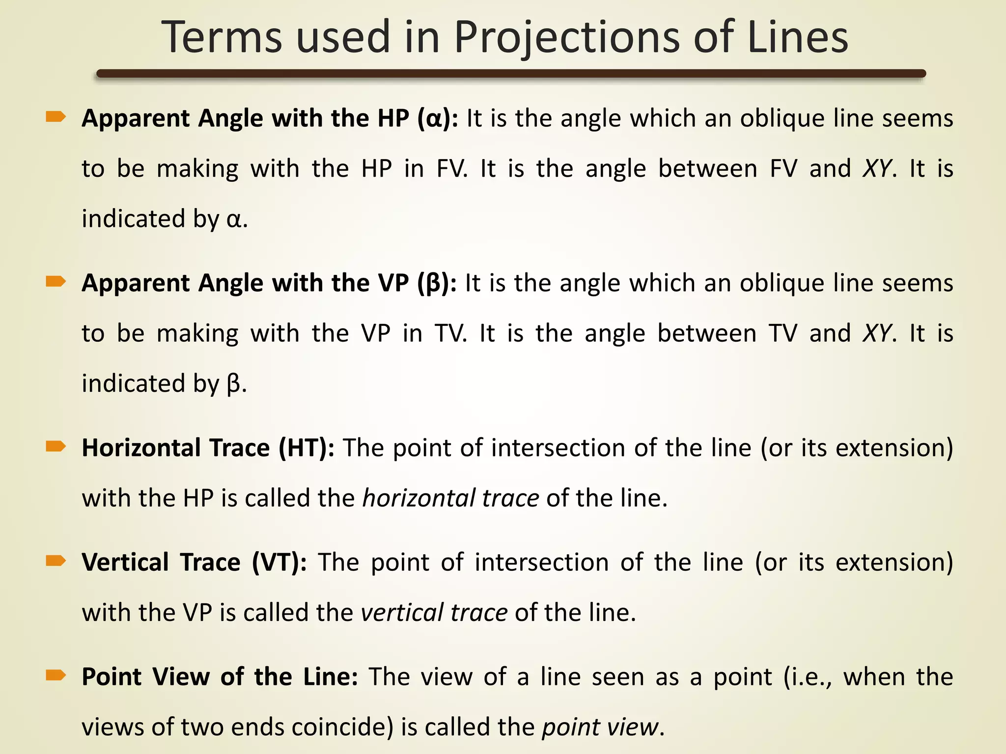
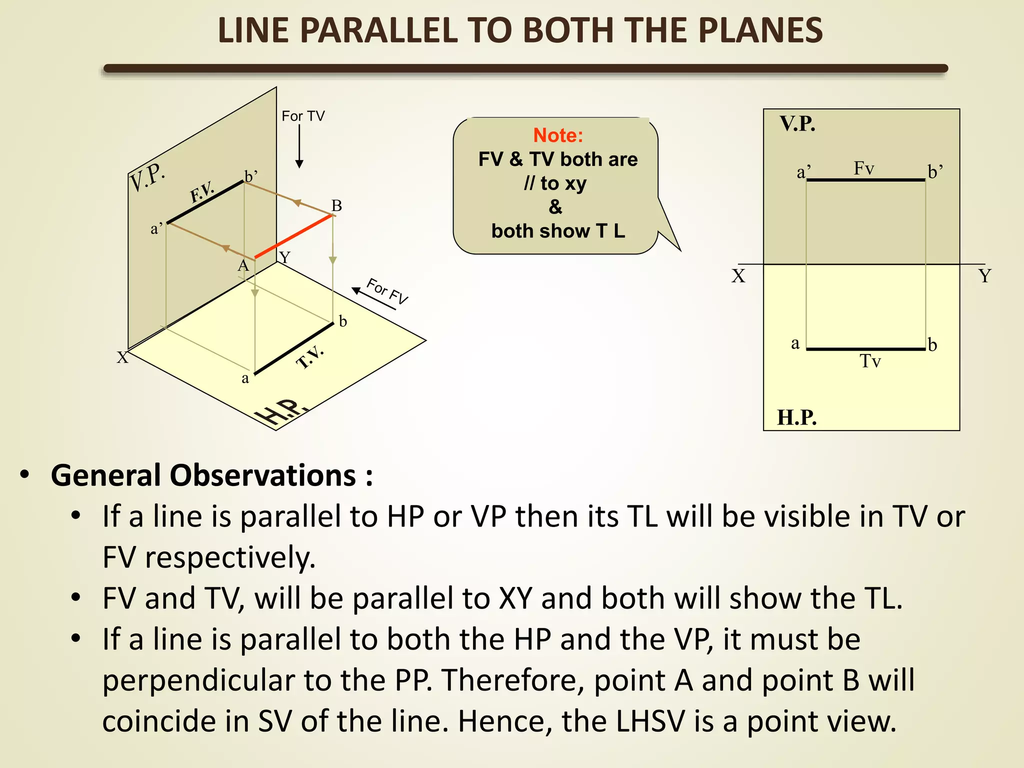
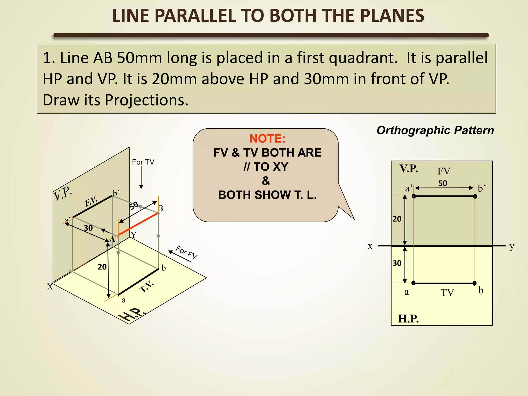
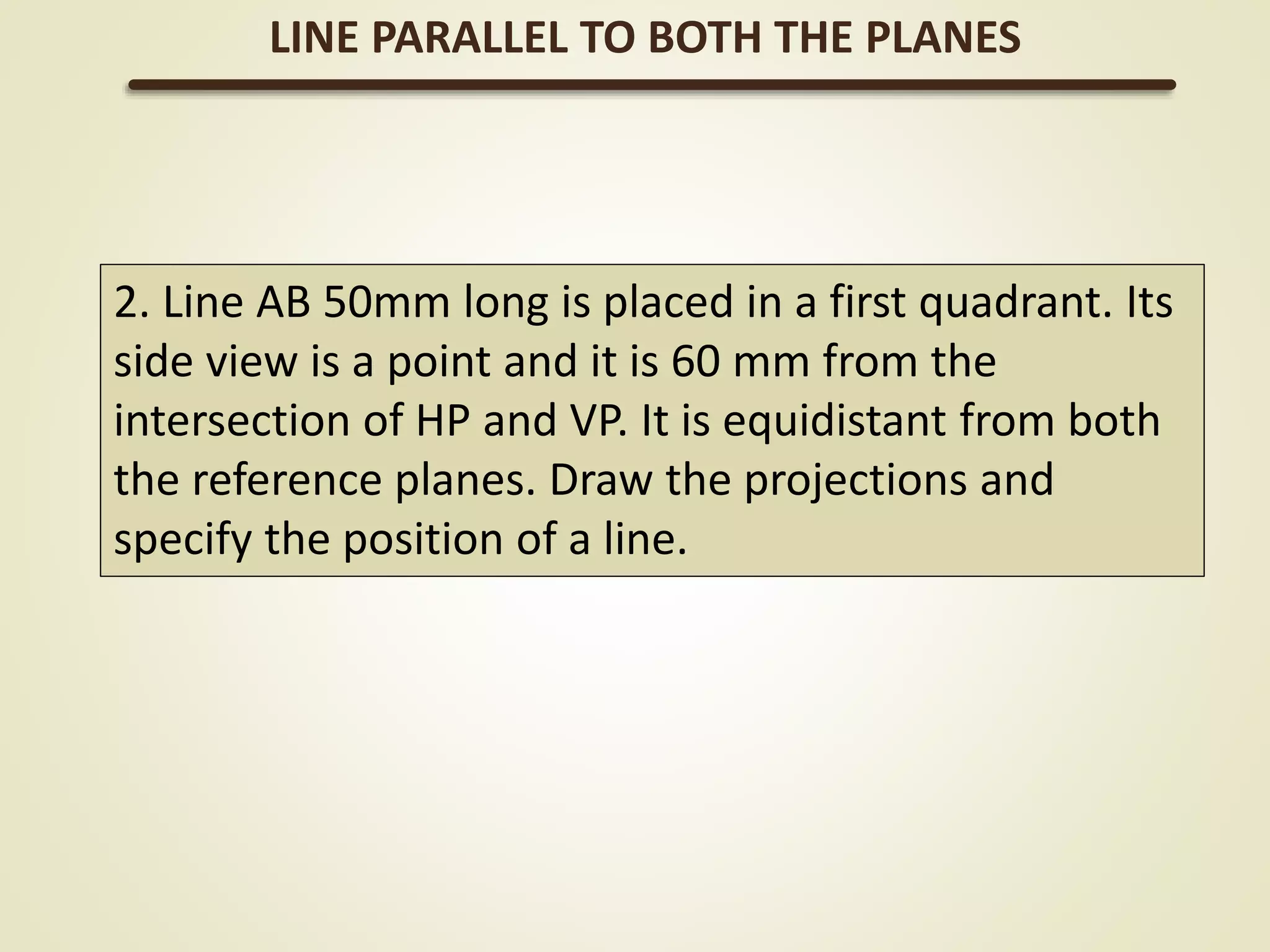
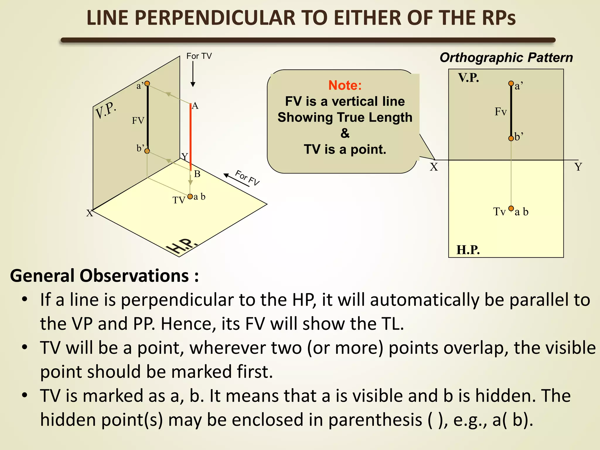
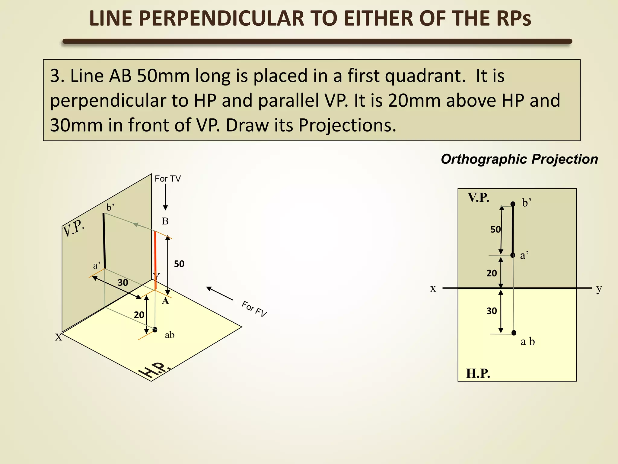
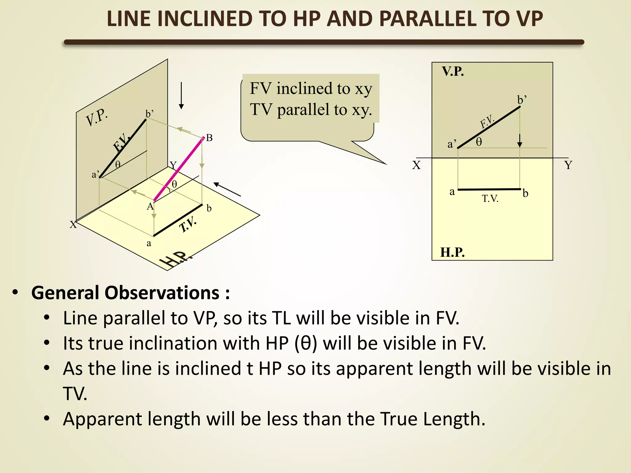
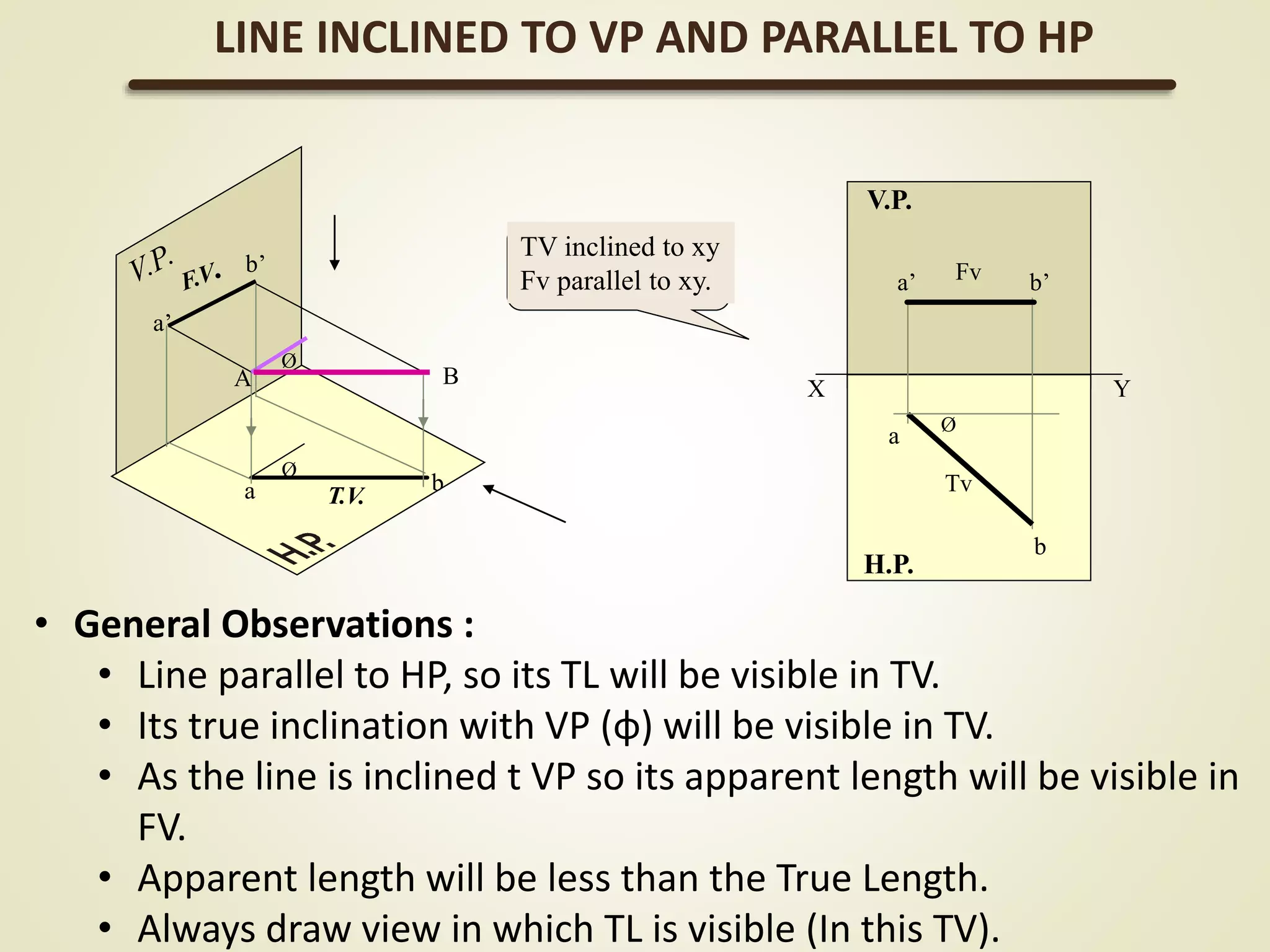
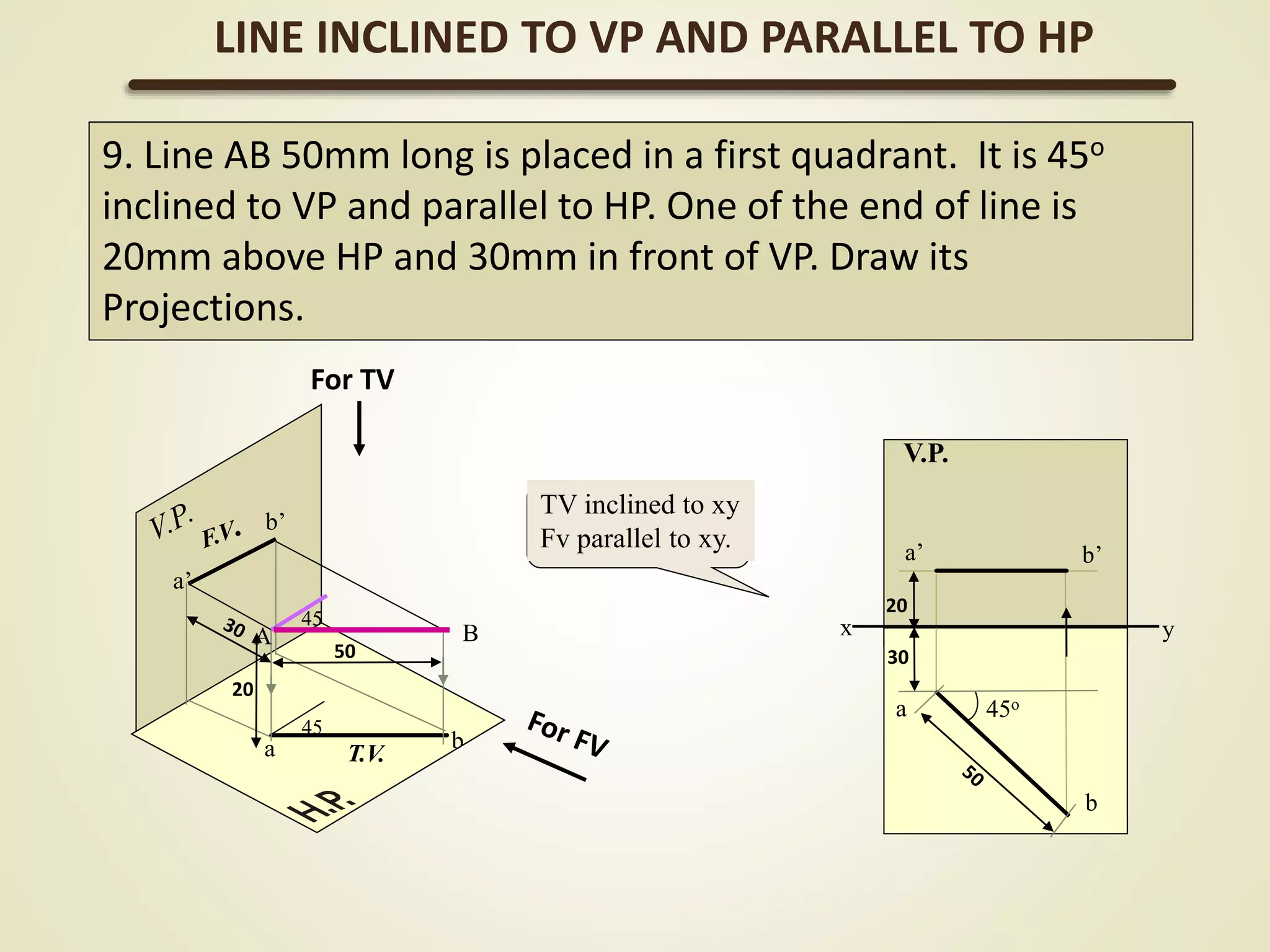
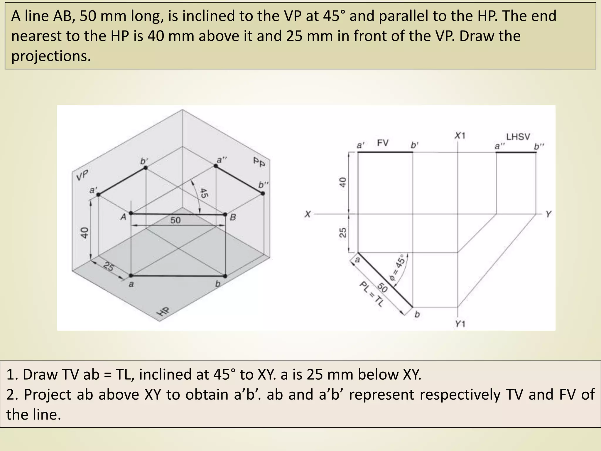
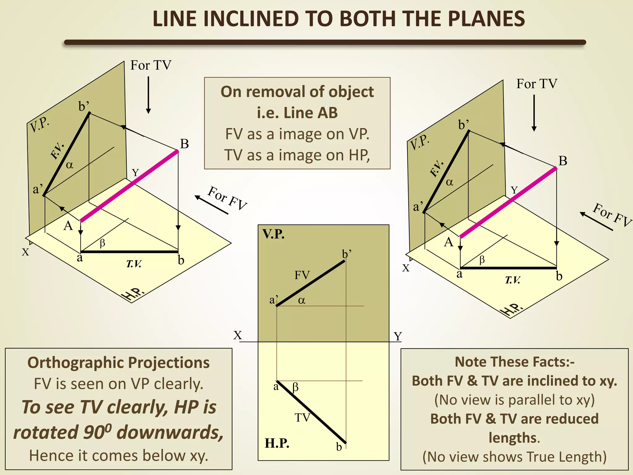
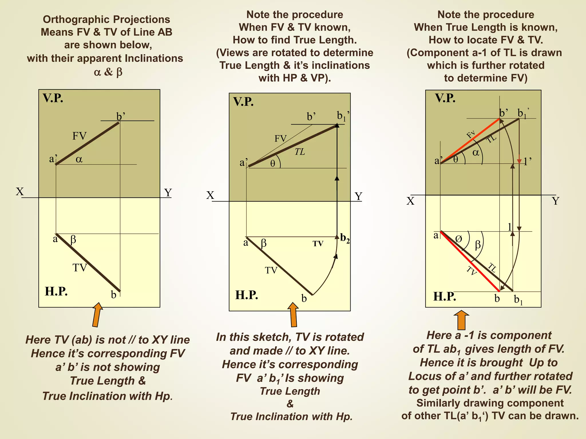
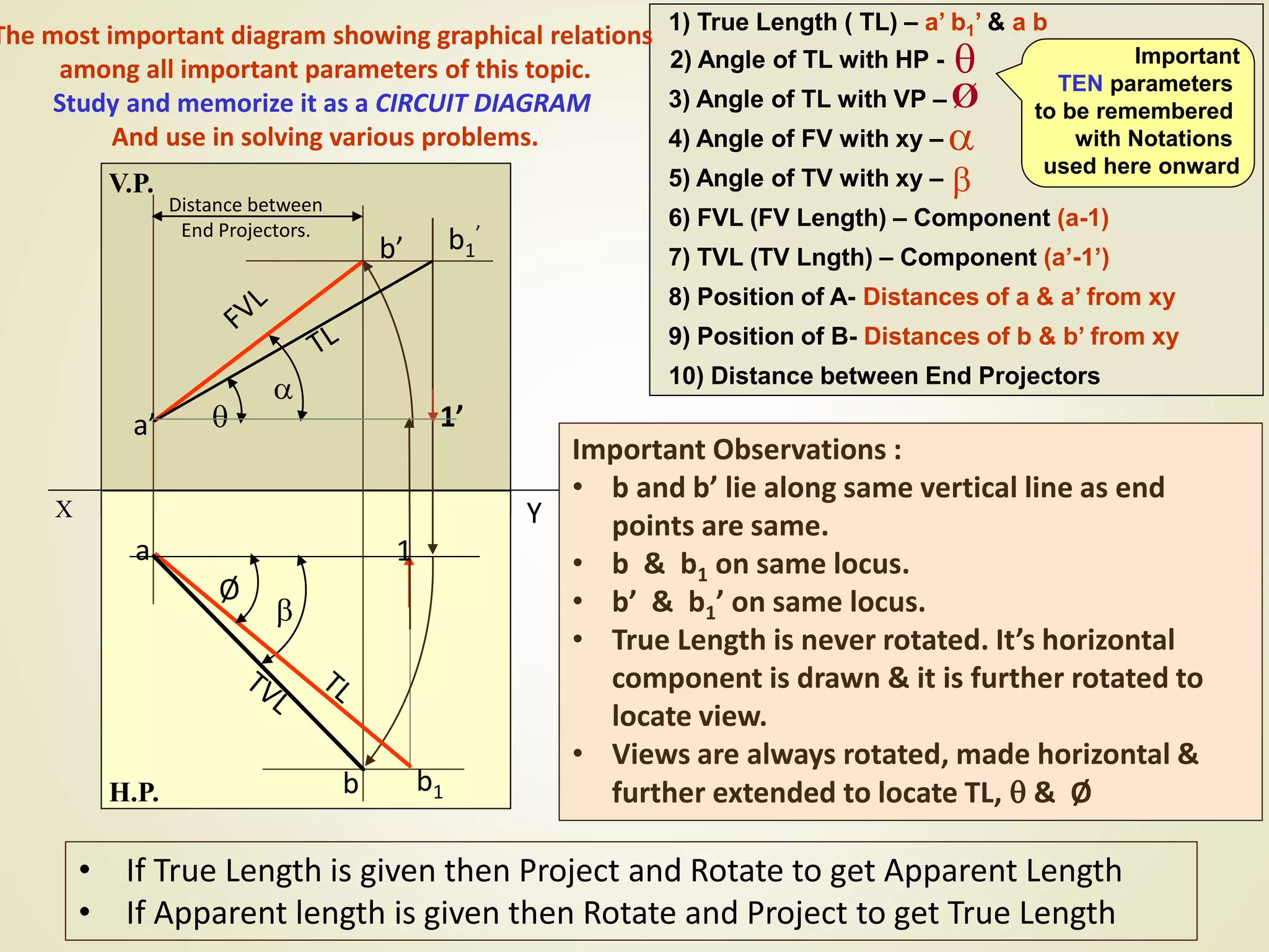
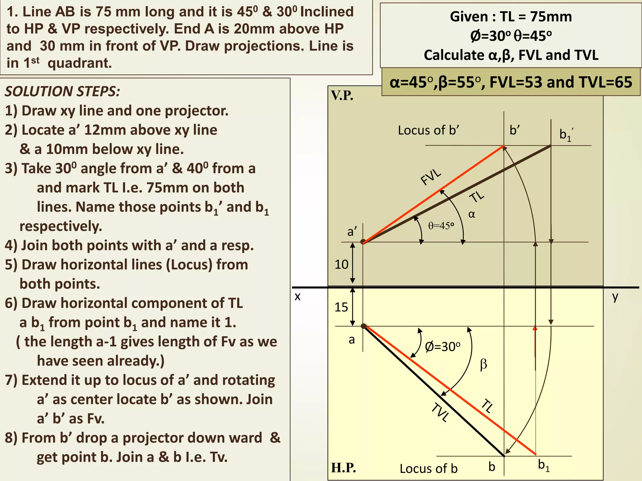
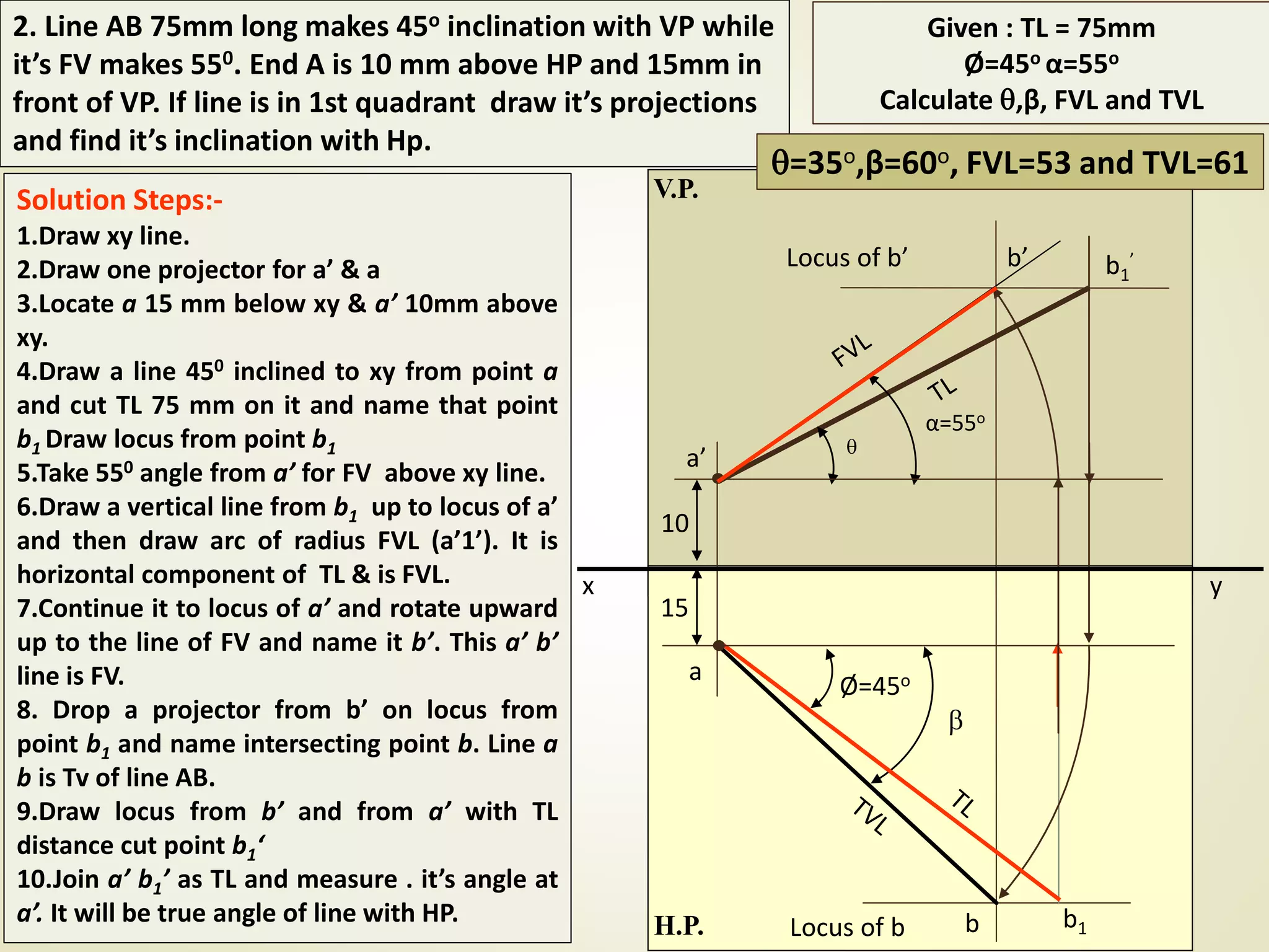
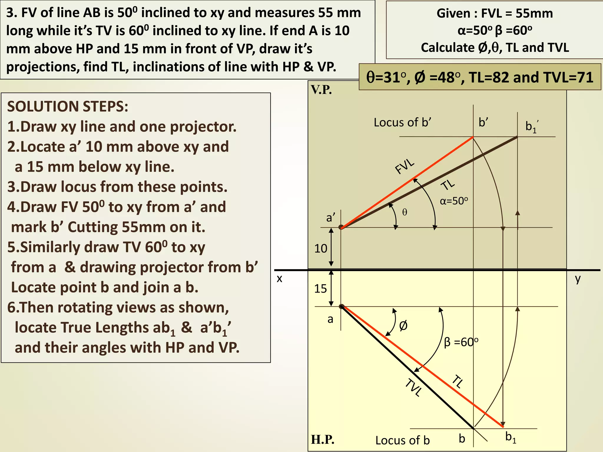
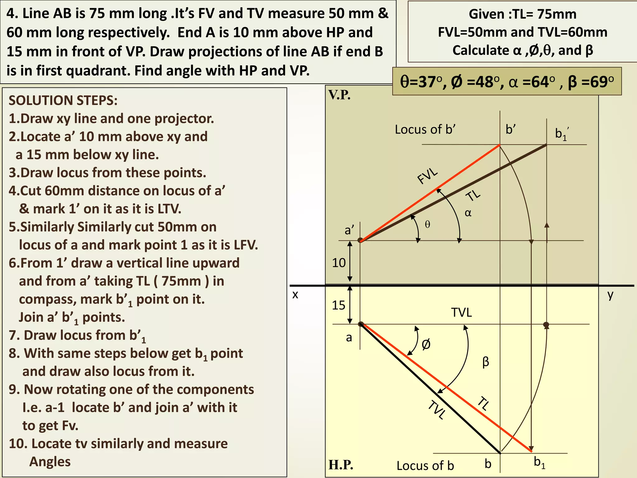
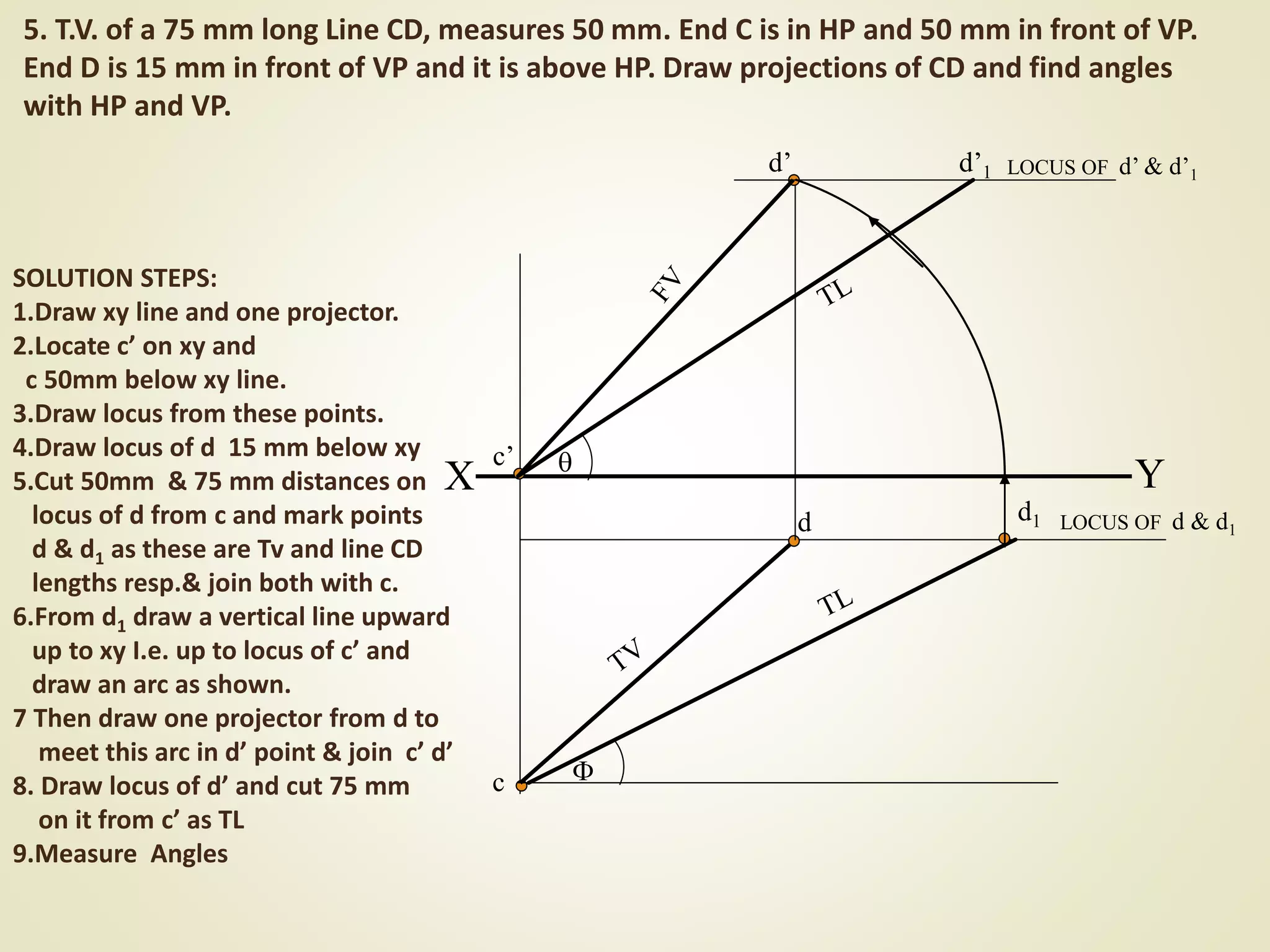
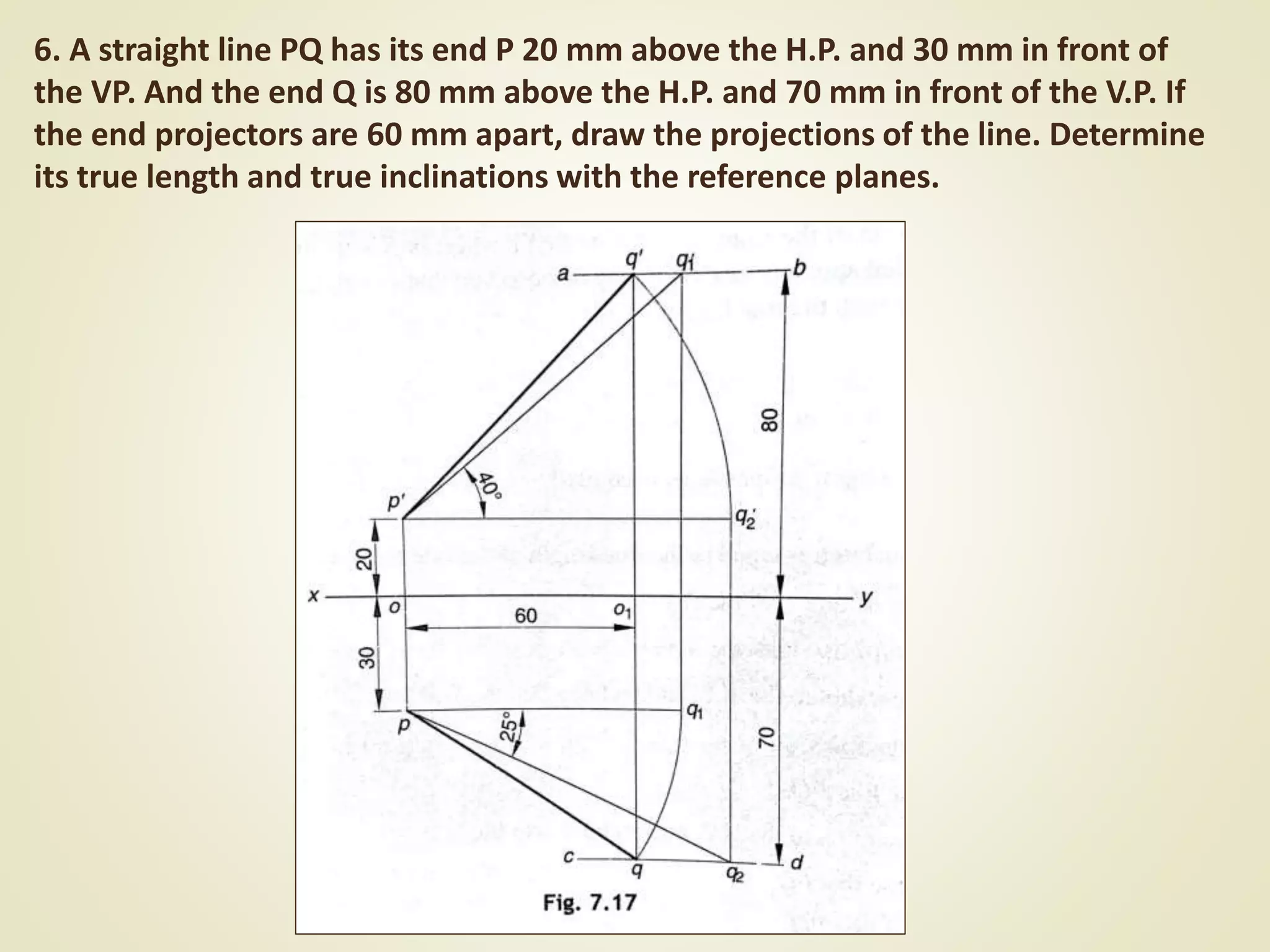
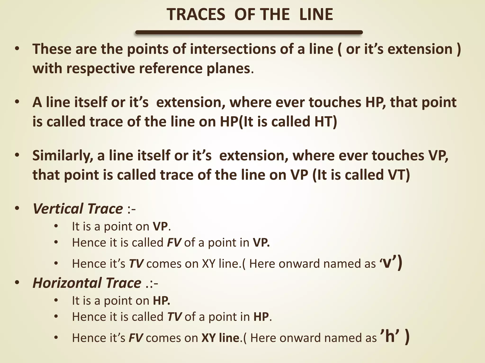
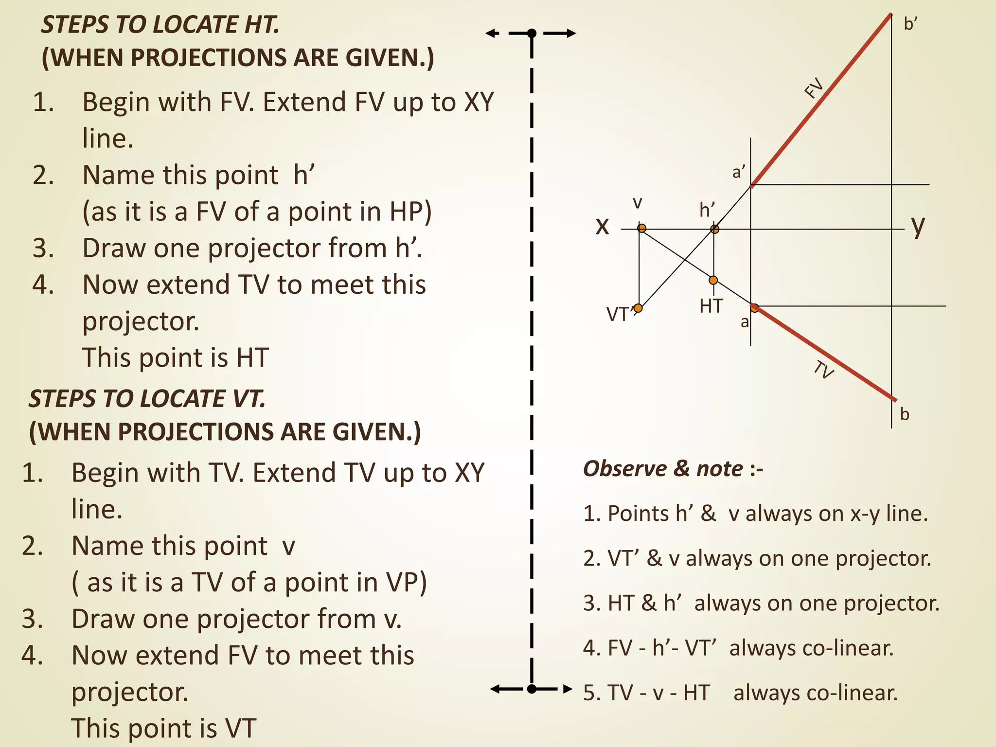
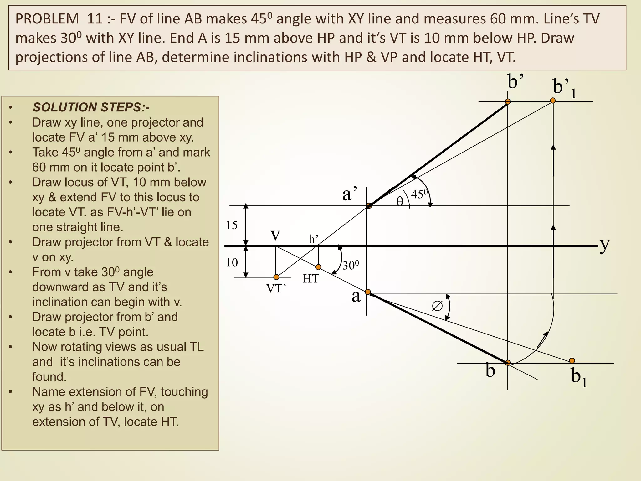
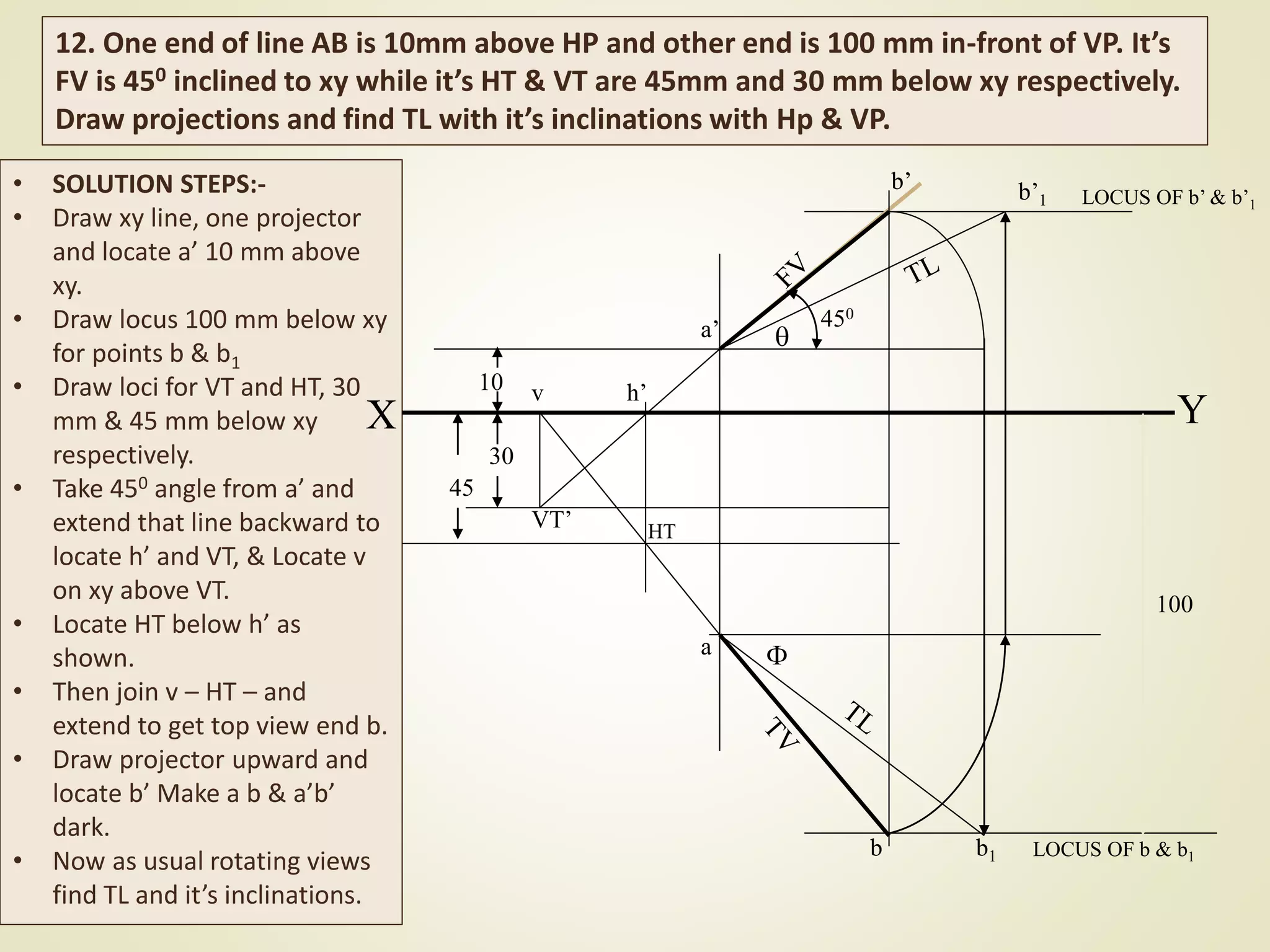
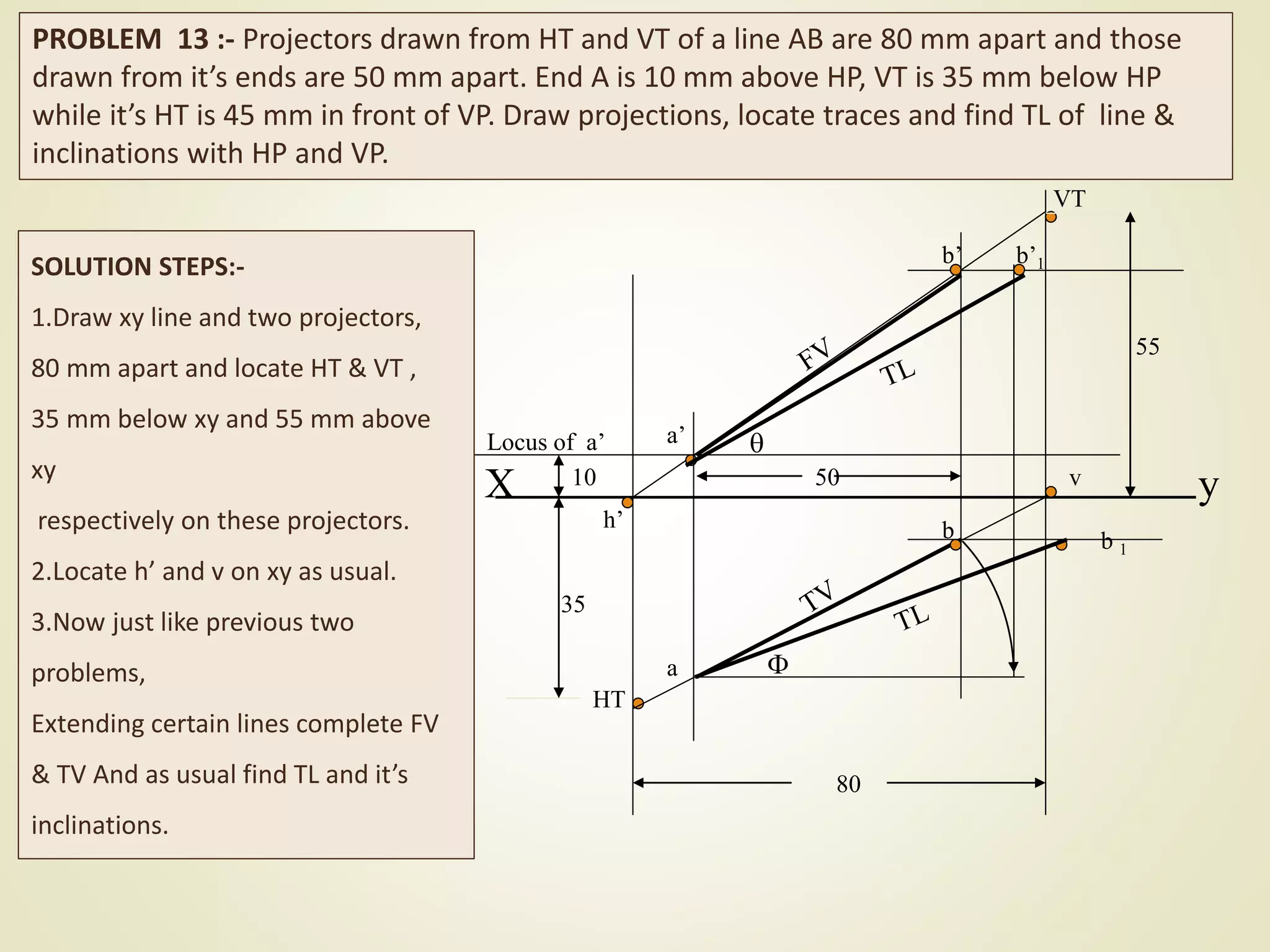

The document provides a detailed explanation of the projections of a straight line in relation to horizontal and vertical planes. It covers various cases such as lines parallel or inclined to these planes, definitions of terms like true length and apparent length, and systematic methods to draw the projections and determine angles of inclination. It includes practical examples to illustrate the application of the concepts in different quadrants.


![Projectionoflines(thedirectdata[1].com)](https://cdn.slidesharecdn.com/ss_thumbnails/projectionoflinesthedirectdata1-170802182419-thumbnail.jpg?width=640&height=640&fit=bounds)


