Download to read offline


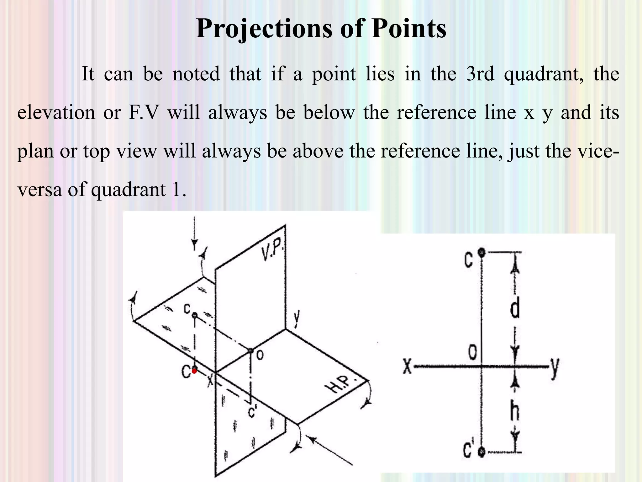


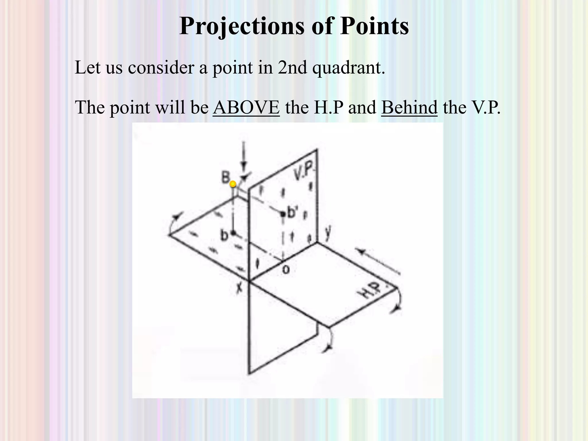
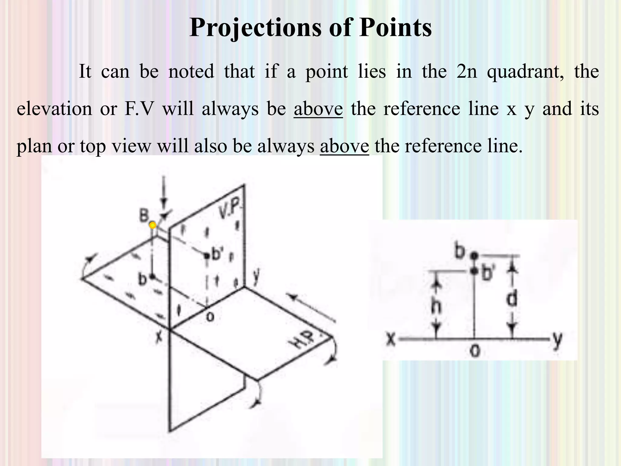


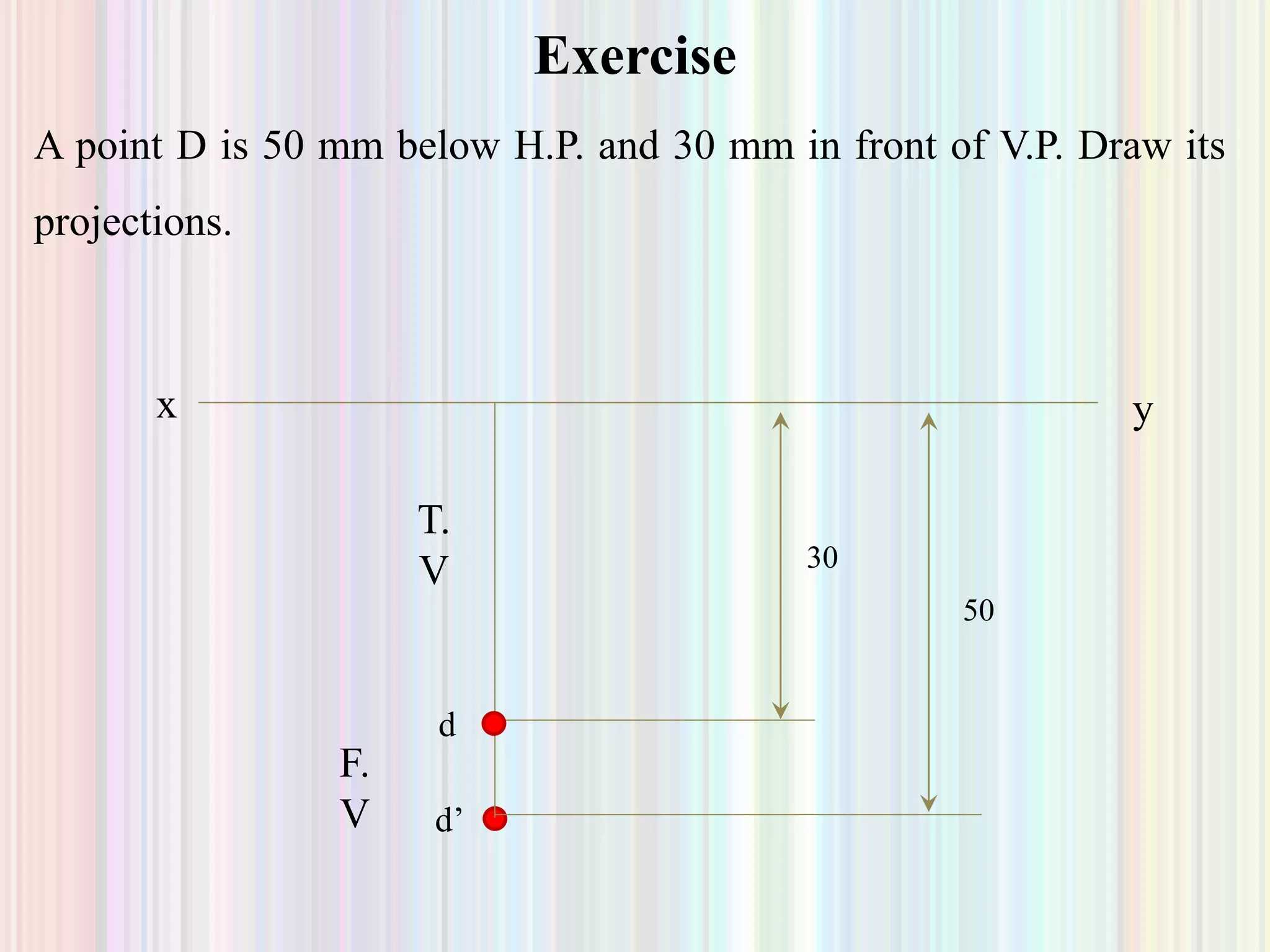
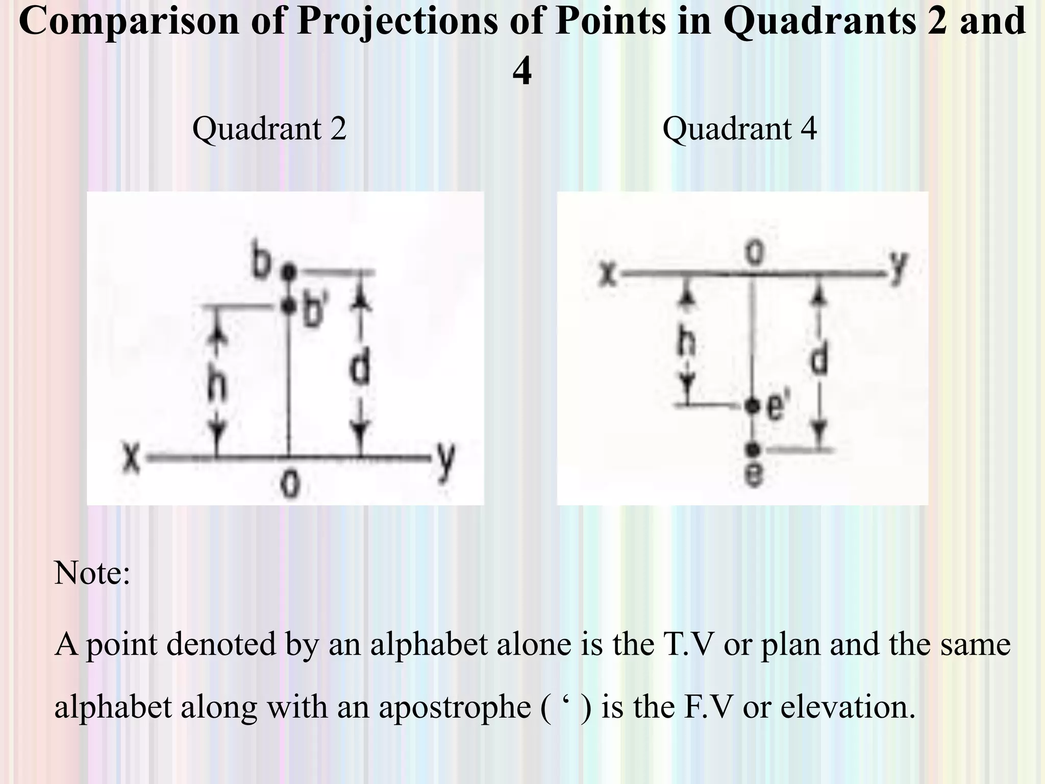


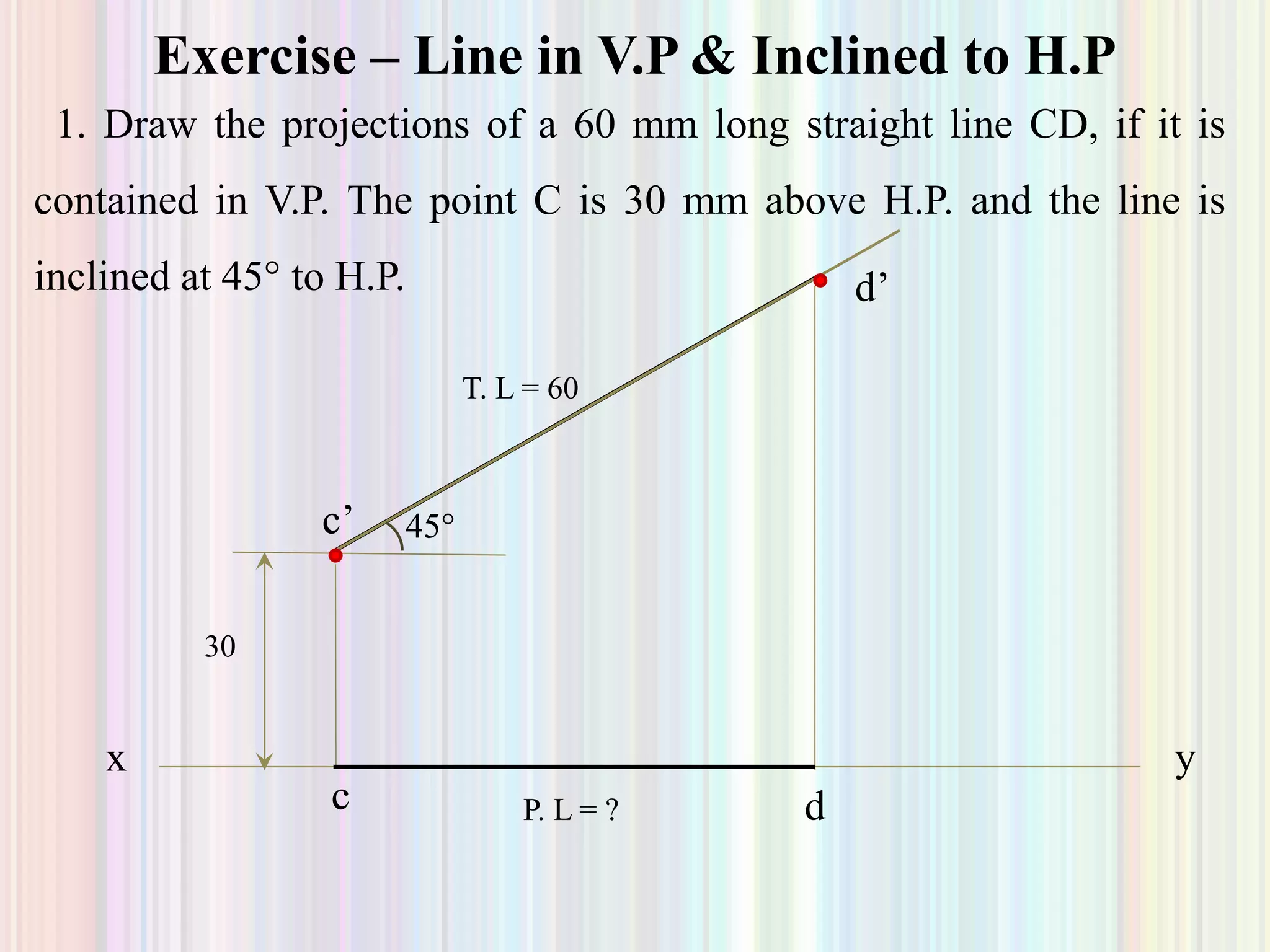

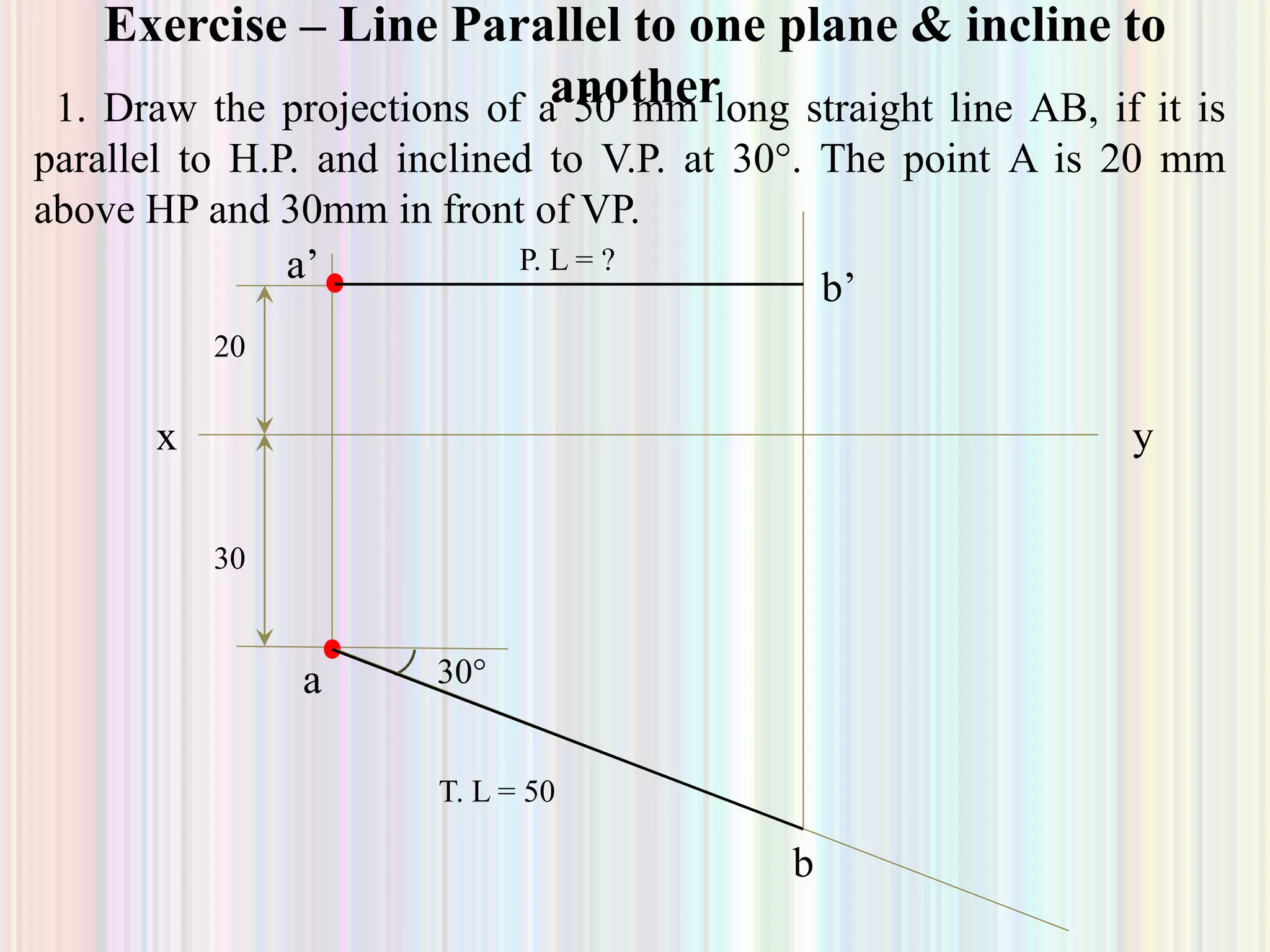


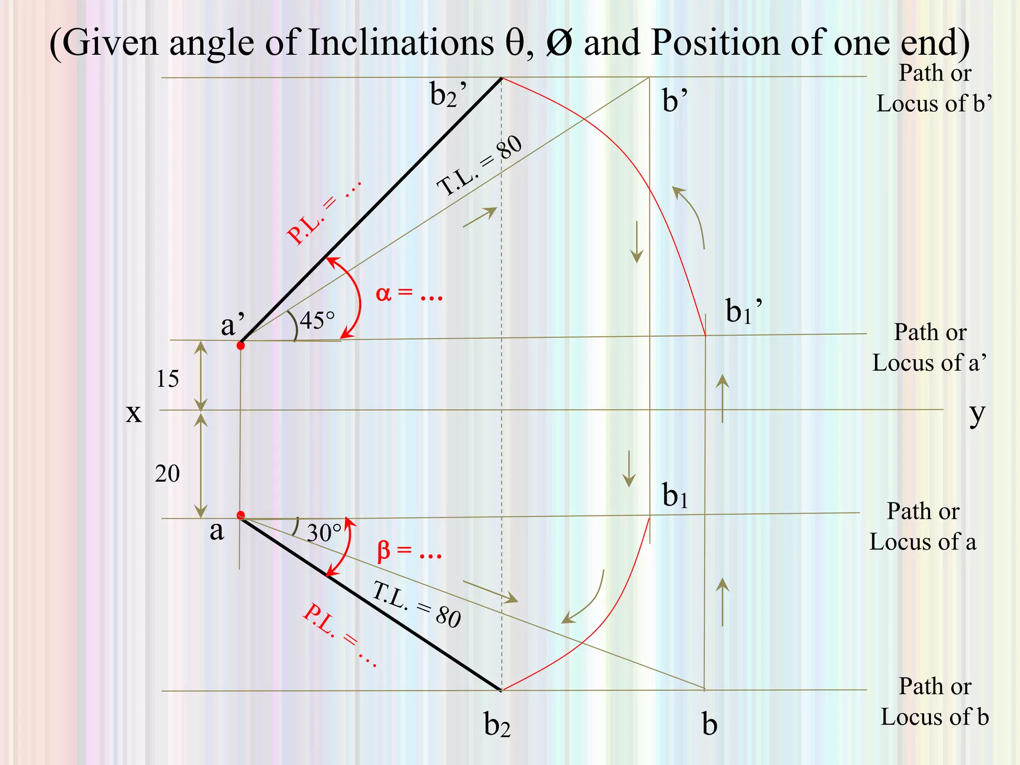


1. The document discusses the projection of points, lines, and plane surfaces. It provides examples of projecting points located in different quadrants and guidelines for indicating true lengths and projections of lines parallel or inclined to the planes. 2. Projection of lines is discussed for lines parallel to or contained within the planes, as well as lines inclined to one or both planes. Examples are given to demonstrate finding the true length, true inclination, or inclination angles of a line based on its projections. 3. Finding projections and true properties of a line is demonstrated through examples where the position of ends, inclination angles, or projected lengths are given to allow calculating the unknowns. Methods are outlined for drawing projections in different cases.


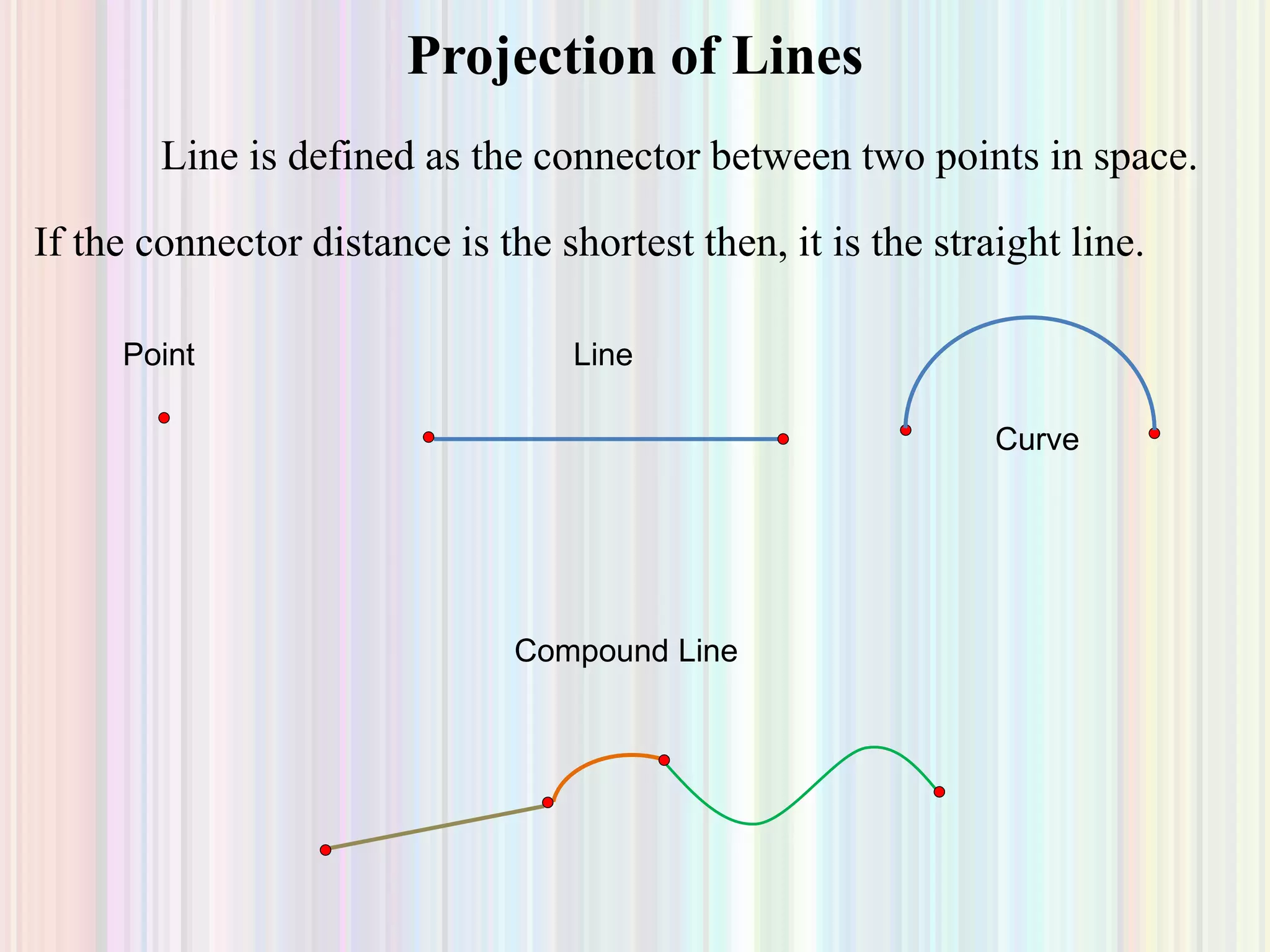
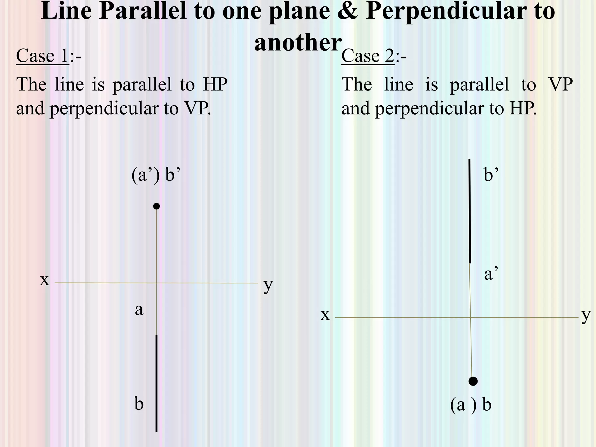
![Projectionoflines(thedirectdata[1].com)](https://cdn.slidesharecdn.com/ss_thumbnails/projectionoflinesthedirectdata1-170802182419-thumbnail.jpg?width=640&height=640&fit=bounds)


