Download to read offline
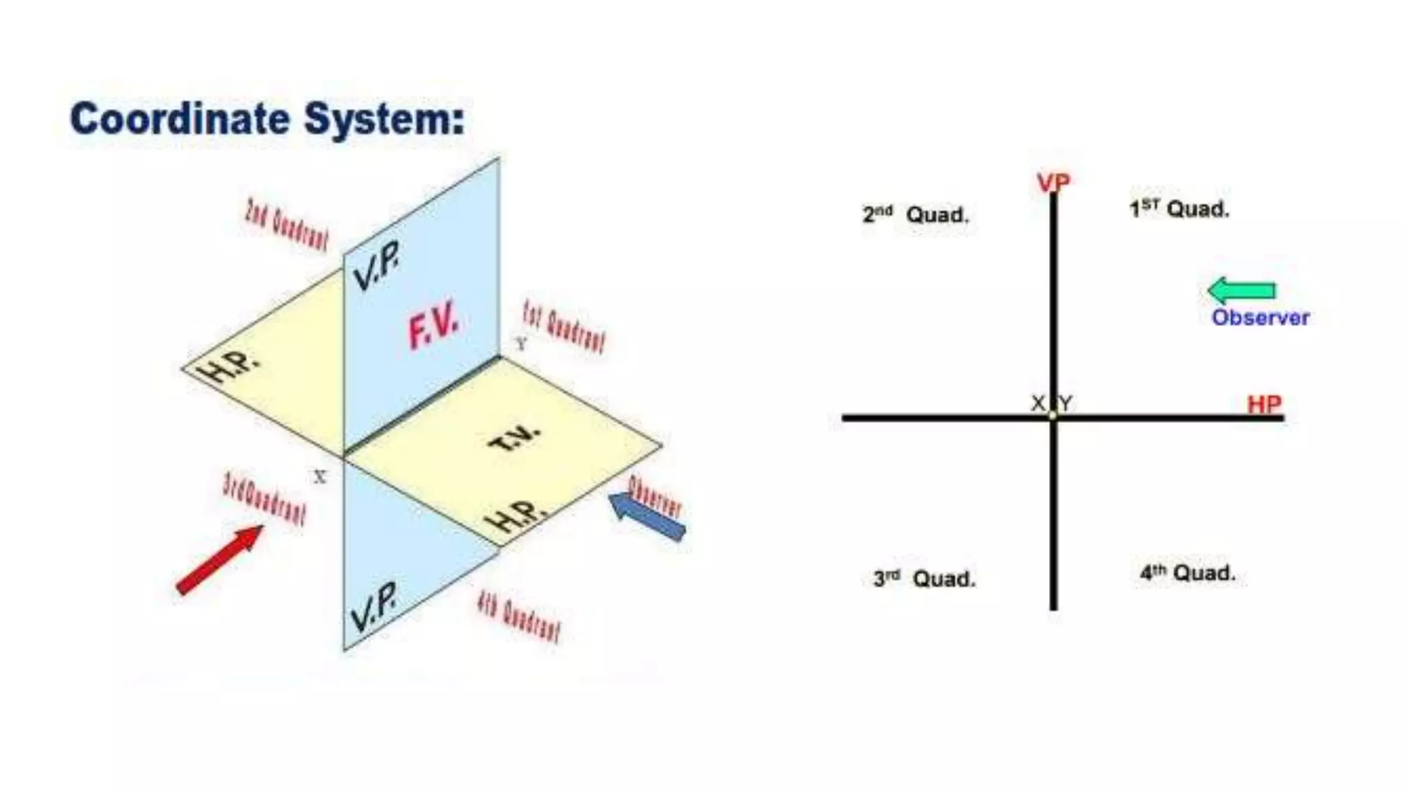

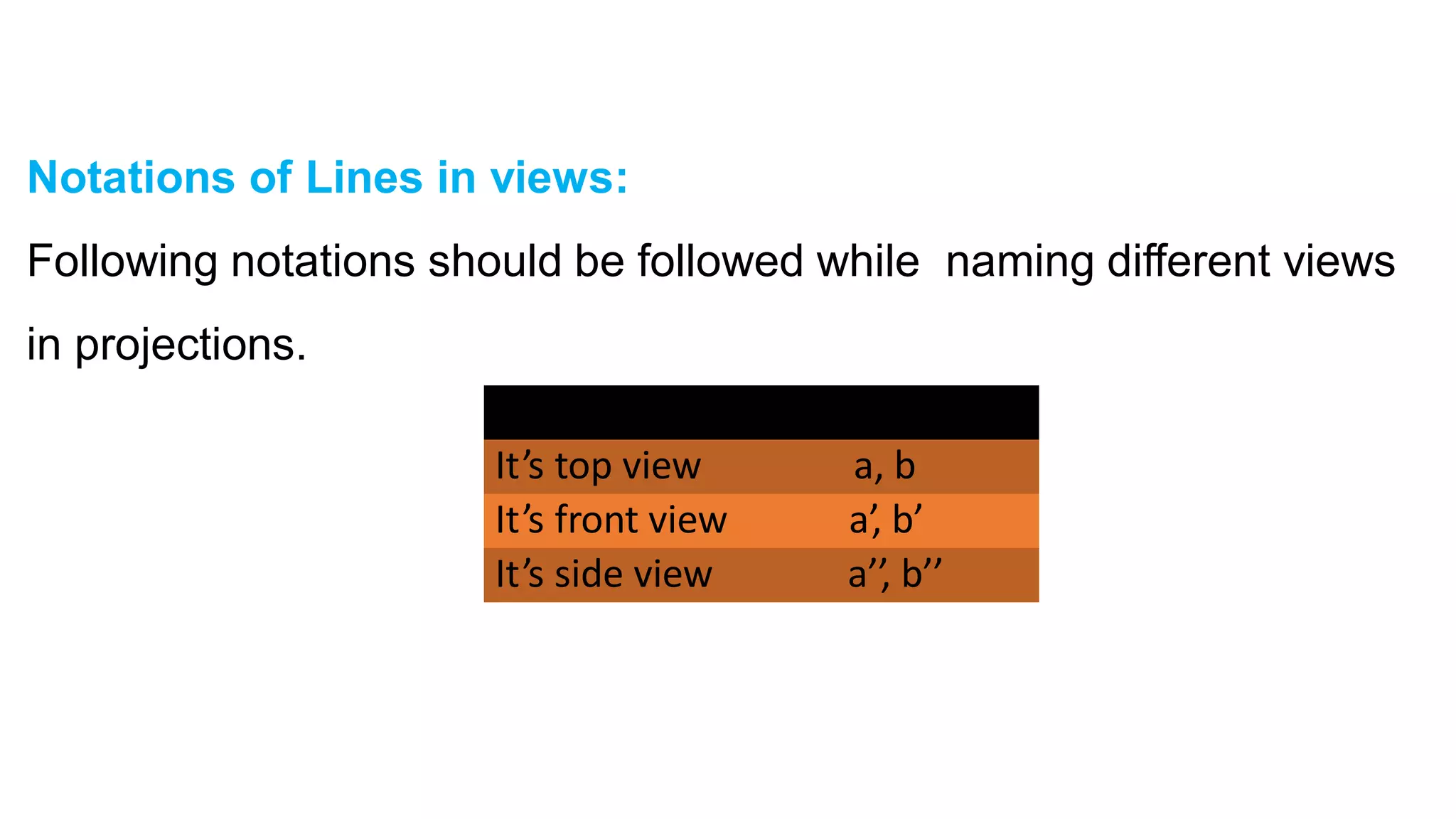
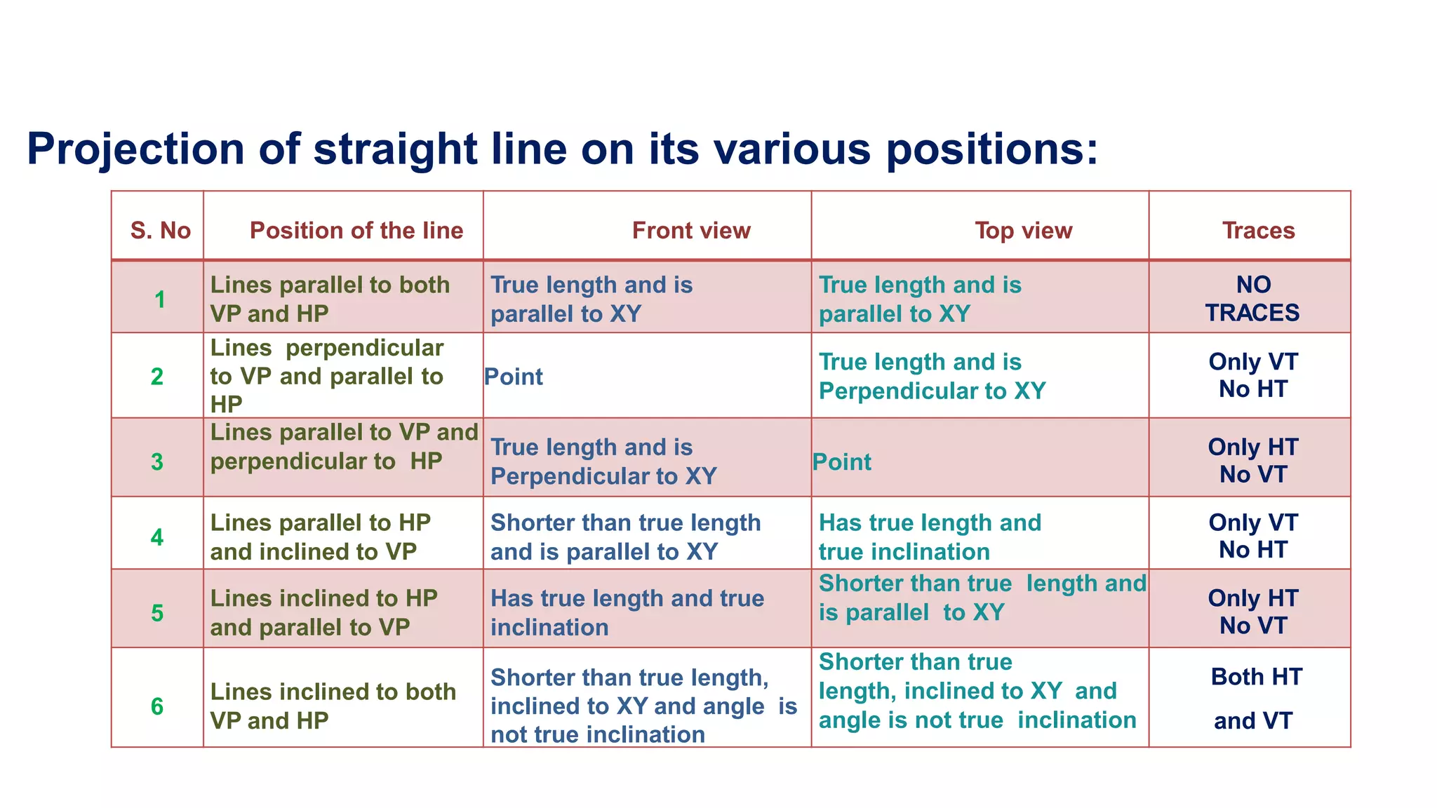

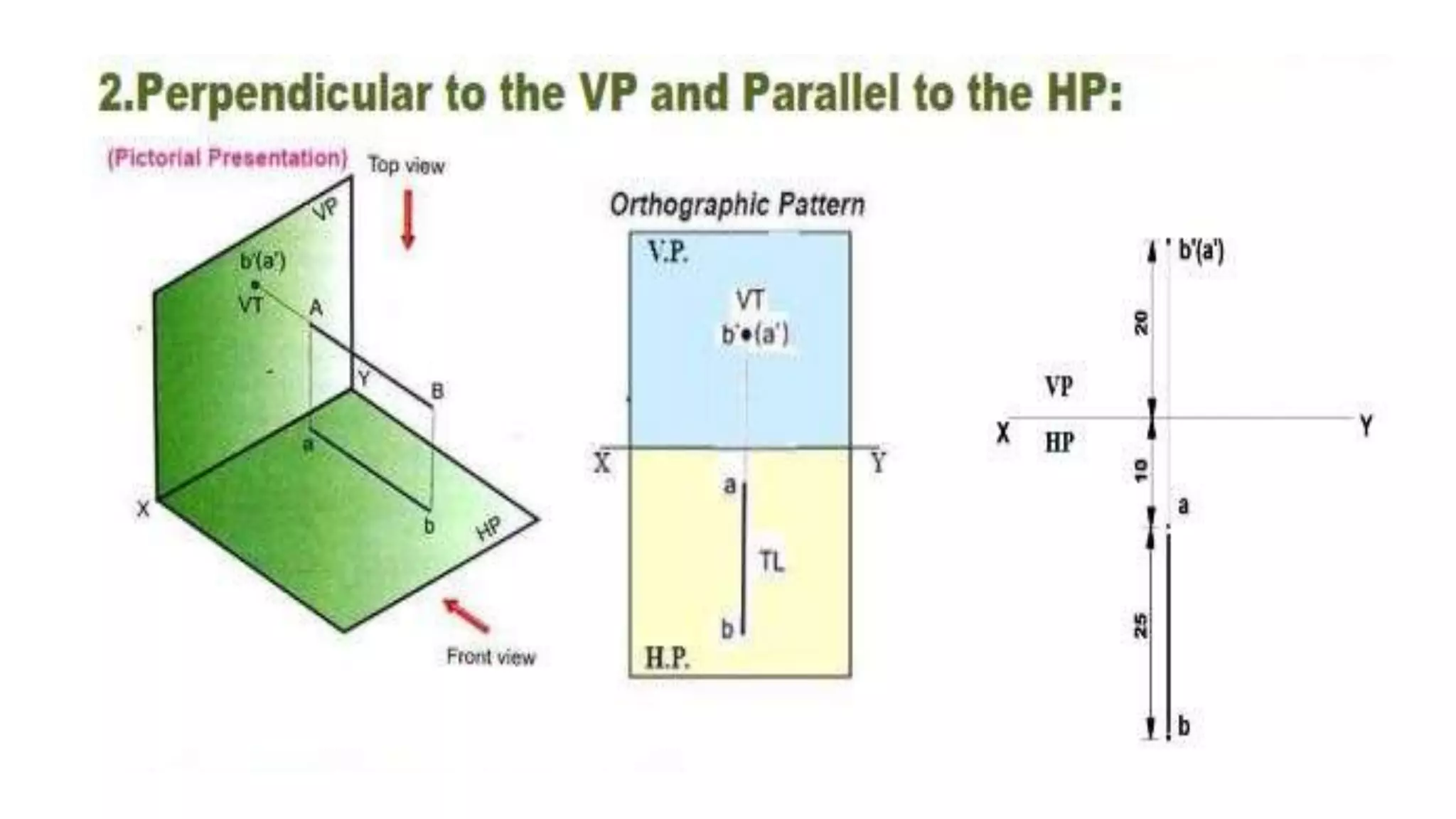
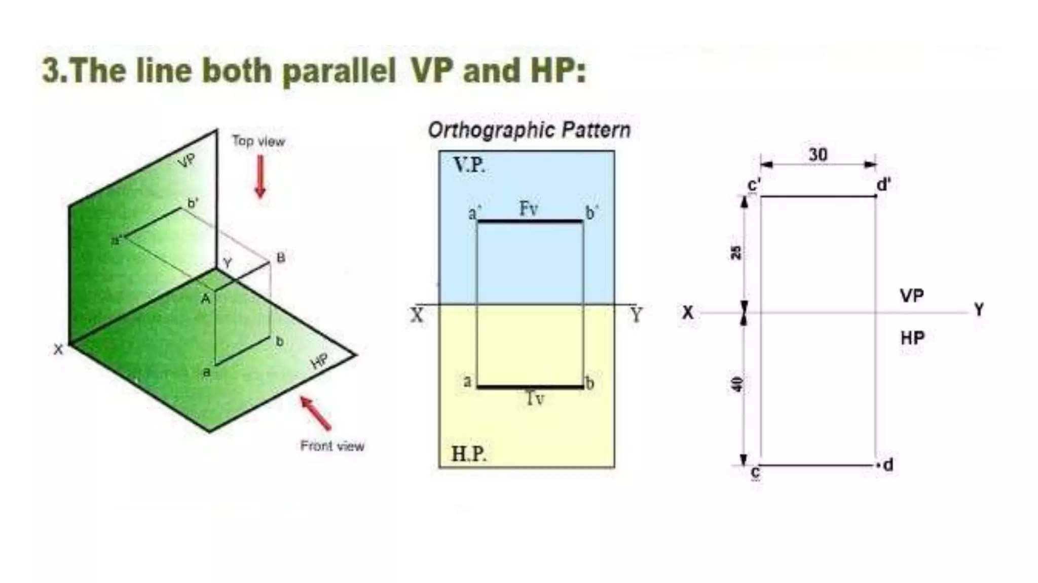


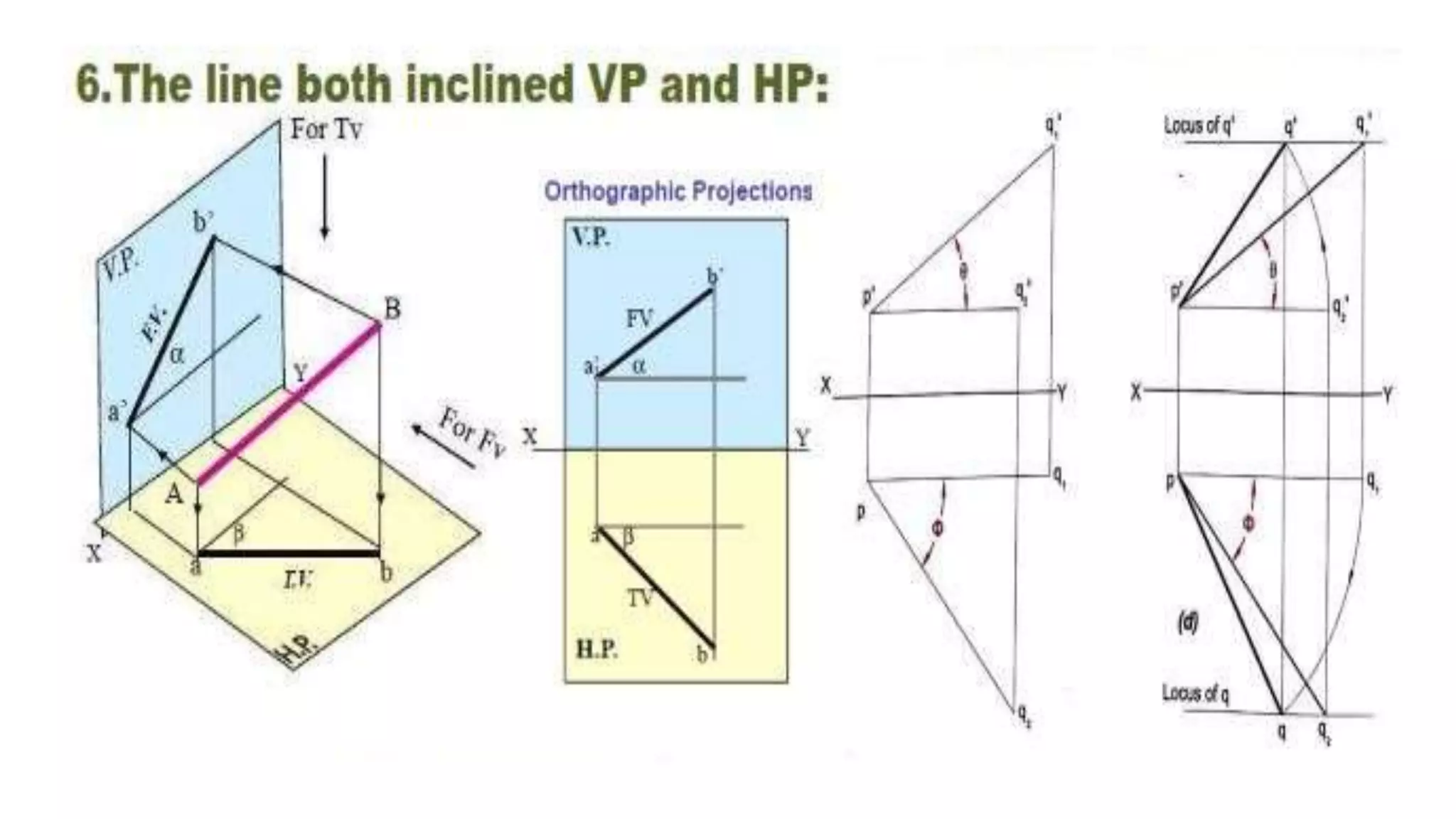
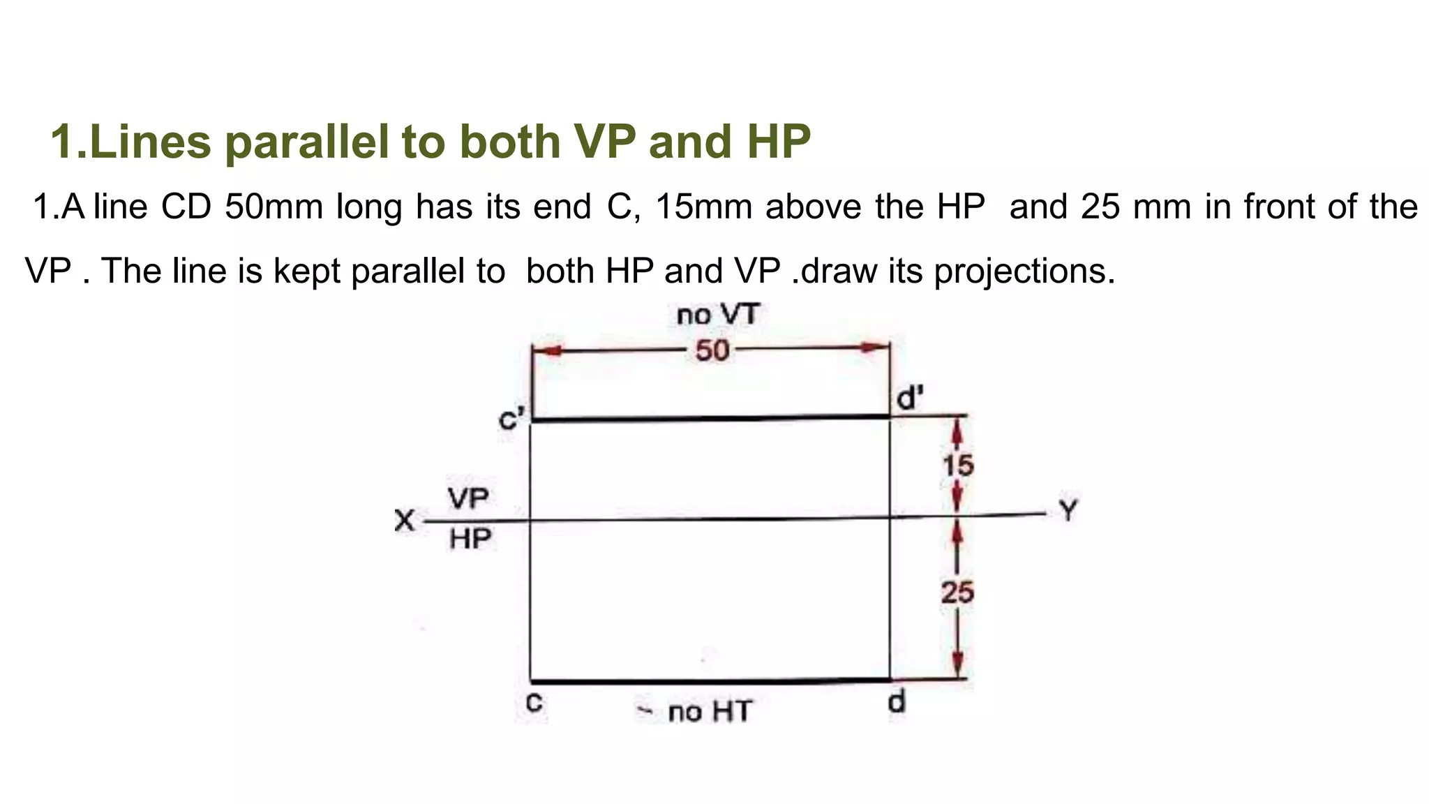

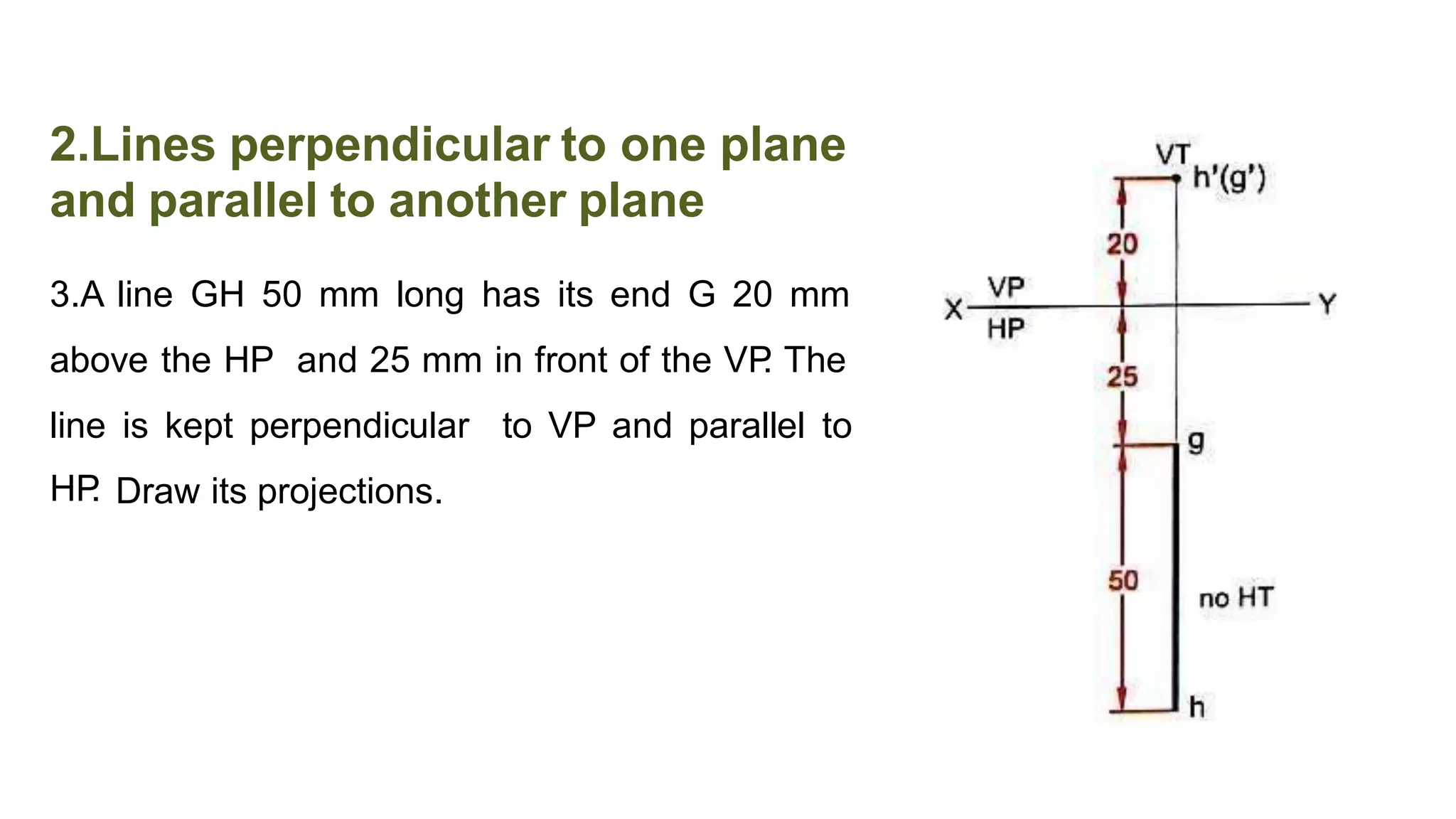


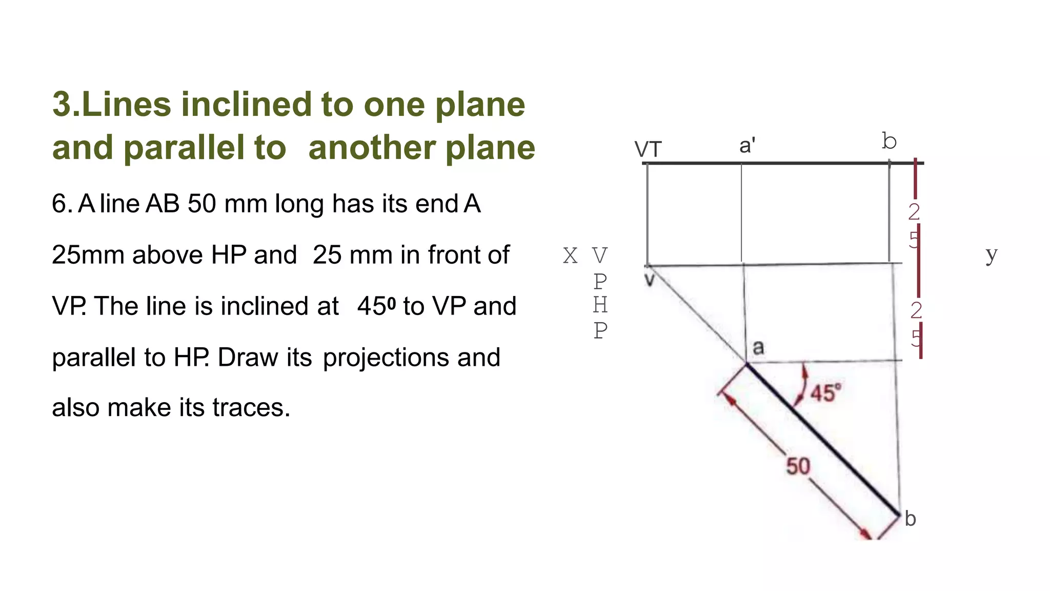

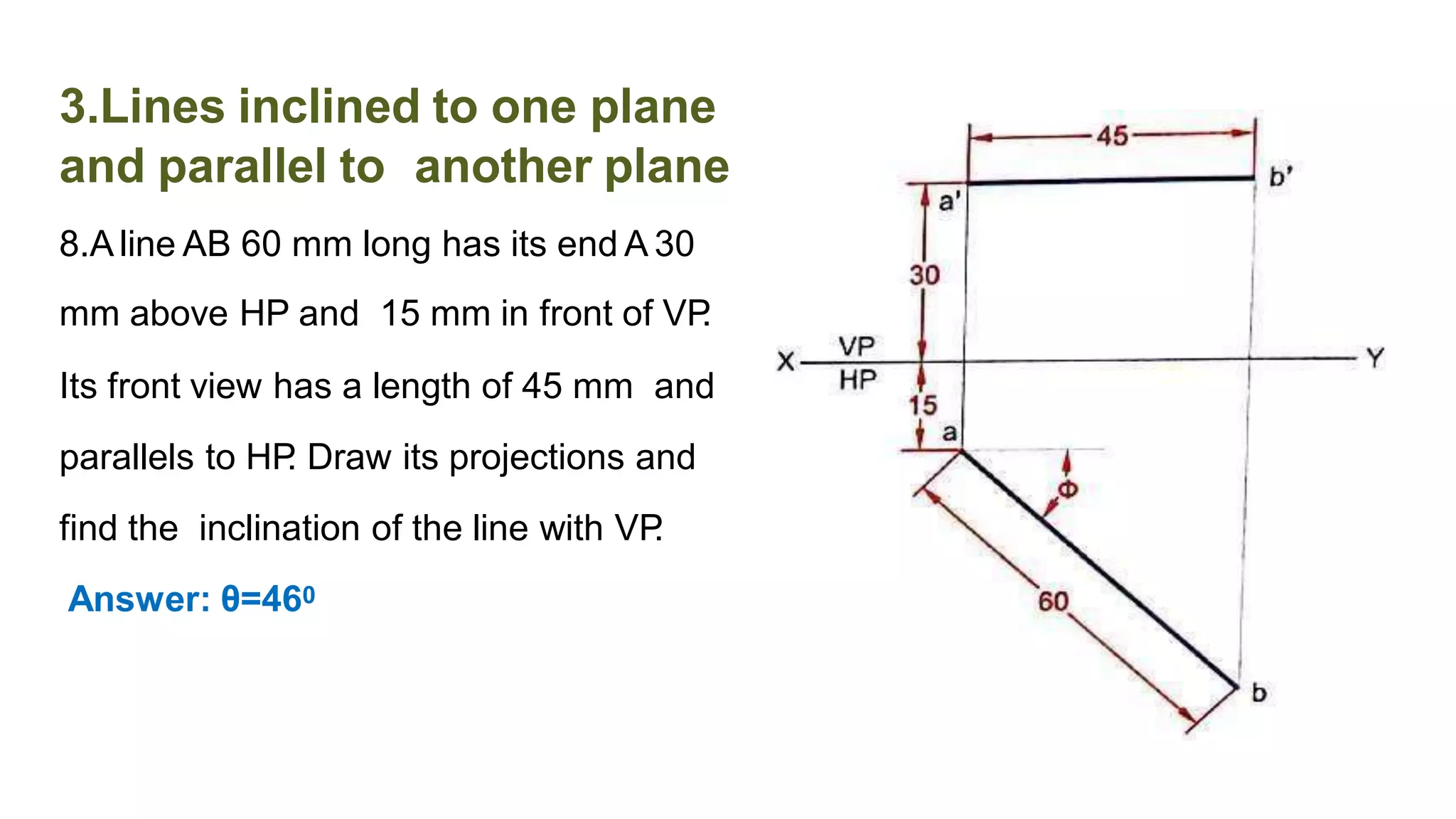


The document discusses the projection of straight lines in engineering drawing. It defines key terms and concepts related to straight lines and their orientation in space. The document then provides examples of how to draw the projections of straight lines that are parallel, perpendicular or inclined to the different planes (vertical and horizontal planes). It demonstrates drawing the projections of lines in different positions and orientations, including showing their traces.


