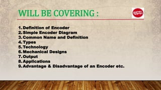
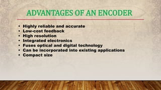
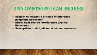
ENCODER
Present By:
Md. Hasan Imam Bijoy
Student of C.S.E
Email: hasan15-11743@diu.edu.bd
Daffodil International University, Dhaka, Bangladesh.
WILL BE COVERING :
1.Definition of Encoder
2.Simple Encoder Diagram
3.Common Name and Definition
4.Types
5.Technology
6.Mechanical Designs
7.Output
8.Applications
9.Advantage & Disadvantage of an Encoder etc.
WHAT IS ENCODER?
An Encoder is a combinational circuit that
performs the reverse operation of Decoder. It
has maximum of 2n input lines and 'n' output
lines. It will produce a binary code equivalent to
the input, which is active High. Therefore,
the encoder encodes 2n input lines with 'n' bits.
ENCODER DIAGRAM
• Rotopulser
• Pulse Generator
• Digital Tachometer
• Tach
• Pulse Tach
• Shaft Encoder
• A Lot of Names.
DIFFERENT NAMES FOR ENCODERS
ROTOPULSER
• Dynapar Series 40 Rotopulser is an economical,
rugged, general purpose optical rotary transducer that
generates an accurate pulse output proportional to
shaft rotation. ... In addition, the 40 Rotopulser line
has been defined by a series of model numbers that
eases selection of the "right" transducer for each
application.
PHOTO OF ROTOPULSER
PULSE GENERATOR
 A pulse generator is either an electronic
circuit or a piece of electronic test
equipment used to generate rectangular
pulses. Pulse generators are used primarily
for working with digital circuits, related
function generators are used primarily for
analog circuits.
PHOTO OF PULSE GENERATOR
– Analog device that
produces a voltage
proportional to speed.
DIGITAL TACHOMETER
Incremental
• Provides identical electronic pulses at each division
of shaft rotation.
• Used for speed or velocity control of motors
 Absolute
• Provides a unique electronic piece of information at each
division of shaft position.
• Used for positioning systems
 Resolver
• Provides sine wave and cosine wave to provide both
velocity and position feedback.
TYPES OF ENCODER
SENSING TECHNOLOGY
Magnetic (Magneto-resistive)
• Tough and simple
• Heavy Duty enough for Mills
• No Optics (no glass breakage)
• Limited to 2048 PPR
 Optical
• Higher Resolution (up to 10,000 PPR)
• Better signal quality
• Shafted and Hollow shaft designs
 Features a magnetic pulse wheel that is imprinted with
numerous, small magnetic poles.
 Rotation of the magnetic pulse wheel creates an
alternating pattern of north-south magnetic fields for the
pick-up head.
 The electrical circuit in the sensor produces digital pulses
proportional to motor speed.
MAGNETO-RESISTIVE TECHNOLOGY
MECHANICAL DESIGN
Hollow Shaft
 Encoder mounting on shaft
extension with bearings and
torque arm.
NorthStar: HSD35,
HSD37, Slim Tach HS56
Dynapar:
HS20 & HS35
MECHANICAL DESIGN
 Coupled
 Machined face, bracket, stub
shaft and a flexible coupling.
NorthStar: RIM 6200, HSD44
Dynapar: H56 Rotopulser
MECHANICAL DESIGN
 Bearingless
 Frame of encoder bolts to
motor, pulse wheel mounts on
shaft extension or stub shaft.
NorthStar:
SLIM Tach:
SL56, SL85, RL67
RIM Tach:
RIM8500, RIM1250
 The lowest cost encoder to install
• No couplings to align or isolate
• No adapter (flower pot)
• No machined fan cover required on TEFC motors
 Flexible torque arm
• Allow encoder to ride freely on shaft extension
• If too rigid, provide stress on encoder bearings
• Arm must be isolated from motor to avoid motor shaft
currents from damaging encoder bearings
HOLLOW SHAFT ENCODERS
Ideal for Reliance TEFC V*S Master motors
 Good for all motor enclosures
COUPLED ENCODERS
 Highest installation cost.
 Requires a expensive, flexible coupling
 Requires adapter (flower pot) between encoder and
motor
 On larger motors, an expensive insulated coupling may
be required to protect Coupled Encoder bearings
 V*S Master TEFC motors requires a special cast iron
machined fan cover
COUPLED ENCODERS
Machined Adapter BracketFlexible Coupling
BEARINGLESS ENCODERS
 Less space required
 No couplings to align or isolate
 Can have a thru shaft
 Can be mounted between brake and
motor
 Can be mounted on drive or non-drive
end
 No bearings to fail!
 Pulse wheel mounted directly on shaft
extension
BEARINGLESS ENCODERS
 Encoder housing bolted to
motor bracket
 No concerns with motor
currents damaging bearings
 Ideal for Reliance RPM-AC and DC motors
 Good to mount between brake and motor
bracket on TENV, DPFV and TEBC-PB
enclosures
 Not recommended for V*S Master motors
HOW ARE ENCODERS CONTROLLED?
 Encoders are controlled through the rotation the shaft it is
mounted to. The shaft comes into contact with a hub which is
in internal to the encoder. As the shaft rotates, it causes the
disc, with both transparent and solid lines, to rotate across
the circuitry of the encoder. The circuitry of the encoder
contains an LED which is captured by a photoelectric diode
and outputs pulses to the user. The speed at which the disc
rotates will be dependent on the speed of the shaft the
encoder is connected to. Anaheim
Automation's optical and magnetic encoder lines are powered
from a single +5VDC power source, and is able to sing and
source 8mA each.
ENCODER OUTPUTS
 Incremental encoders are usually supplied with two
channels (A & B) that are offset by 90 degrees.
 If complements are included (A, B ), the signal is
“quadrature”, providing speed of rotation AND direction of
rotation.
A
A
Encoder
B
B
MARKER PULSE
 A marker pulse (reference, index or Z pulse) is a once per
revolution pulse that occurs at precisely the same
mechanical point in a 360º revolution of the encoder shaft.
B
A
Z
Marker
Although a “Marker” pulse is standard on some encoders, it is
additional feature (charge) on many encoders. Ask for one, if you
need one.
HOW TO SELECT AN ENCODER
There are several important criteria involved in
selecting the proper encoder:
1. Output
2. Desired Resolution (CPR)
3. Noise and Cable Length
4. Index Channel
5. Cover/Base
APPLICATIONS FOR ENCODERS
An encoder can be used in applications requiring feedback of
position, velocity, distance, etc. The examples listed below
illustrate the vast capabilities and implementations of an
encoder:
• Robotics
• Labeling Machines
• Medical Equipment
• Textiles
• Drilling Machines
• Motor Feedback
APPLICATIONS FOR ENCODERS
 Assembly Machines
 Packaging
 X and Y Indication Systems
 Printers
 Testing Machines
 CNC Machines
ENCODERS ARE USED IN MANY INDUSTRIES
Encoders have become an essential component to applications in
many different industries. The following is a partial list of industries
making use of encoders:
 Automotive – The automotive industry utilize encoders as sensors of
mechanical motion may be applied to controlling speed.
 Consumer Electronics and Office Equipment – In the consumer
electronics industry, encoders are widely used office equipment
such as PC-based scanning equipment, printers, and scanners.
ENCODERS ARE USED IN MANY INDUSTRIES
 Industrial – In the industrial industry, encoders are used in labeling
machines, packaging and machine tooling with single and multi-
axis motor controllers. Encoders can also be found in CNC
machine control.
 Medical – In the medical industry, encoders are utilized in medical
scanners, microscopic or nanoscopic motion control of automated
devices and dispensing pumps.
 Military - The military also utilizes encoders in their application of
positioning antennas.
 Scientific Instruments – Scientific equipment implement encoders
in the positioning of an observatory telescope.
ADVANTAGES OF AN ENCODER
 Highly reliable and accurate
 Low-cost feedback
 High resolution
 Integrated electronics
 Fuses optical and digital technology
 Can be incorporated into existing applications
 Compact size
DISADVANTAGES OF AN ENCODER
 Subject to magnetic or radio interference
(Magnetic Encoders)
 Direct light source interference (Optical
Encoders)
 Susceptible to dirt, oil and dust contaminates
THANK YOU

Encoder

  • 1.
    ENCODER Present By: Md. HasanImam Bijoy Student of C.S.E Email: hasan15-11743@diu.edu.bd Daffodil International University, Dhaka, Bangladesh.
  • 2.
    WILL BE COVERING: 1.Definition of Encoder 2.Simple Encoder Diagram 3.Common Name and Definition 4.Types 5.Technology 6.Mechanical Designs 7.Output 8.Applications 9.Advantage & Disadvantage of an Encoder etc.
  • 3.
    WHAT IS ENCODER? AnEncoder is a combinational circuit that performs the reverse operation of Decoder. It has maximum of 2n input lines and 'n' output lines. It will produce a binary code equivalent to the input, which is active High. Therefore, the encoder encodes 2n input lines with 'n' bits.
  • 4.
  • 5.
    • Rotopulser • PulseGenerator • Digital Tachometer • Tach • Pulse Tach • Shaft Encoder • A Lot of Names. DIFFERENT NAMES FOR ENCODERS
  • 6.
    ROTOPULSER • Dynapar Series40 Rotopulser is an economical, rugged, general purpose optical rotary transducer that generates an accurate pulse output proportional to shaft rotation. ... In addition, the 40 Rotopulser line has been defined by a series of model numbers that eases selection of the "right" transducer for each application.
  • 7.
  • 8.
    PULSE GENERATOR  Apulse generator is either an electronic circuit or a piece of electronic test equipment used to generate rectangular pulses. Pulse generators are used primarily for working with digital circuits, related function generators are used primarily for analog circuits.
  • 9.
    PHOTO OF PULSEGENERATOR
  • 10.
    – Analog devicethat produces a voltage proportional to speed. DIGITAL TACHOMETER
  • 11.
    Incremental • Provides identicalelectronic pulses at each division of shaft rotation. • Used for speed or velocity control of motors  Absolute • Provides a unique electronic piece of information at each division of shaft position. • Used for positioning systems  Resolver • Provides sine wave and cosine wave to provide both velocity and position feedback. TYPES OF ENCODER
  • 12.
    SENSING TECHNOLOGY Magnetic (Magneto-resistive) •Tough and simple • Heavy Duty enough for Mills • No Optics (no glass breakage) • Limited to 2048 PPR  Optical • Higher Resolution (up to 10,000 PPR) • Better signal quality • Shafted and Hollow shaft designs
  • 13.
     Features amagnetic pulse wheel that is imprinted with numerous, small magnetic poles.  Rotation of the magnetic pulse wheel creates an alternating pattern of north-south magnetic fields for the pick-up head.  The electrical circuit in the sensor produces digital pulses proportional to motor speed. MAGNETO-RESISTIVE TECHNOLOGY
  • 14.
  • 15.
    MECHANICAL DESIGN Hollow Shaft Encoder mounting on shaft extension with bearings and torque arm. NorthStar: HSD35, HSD37, Slim Tach HS56 Dynapar: HS20 & HS35
  • 16.
    MECHANICAL DESIGN  Coupled Machined face, bracket, stub shaft and a flexible coupling. NorthStar: RIM 6200, HSD44 Dynapar: H56 Rotopulser
  • 17.
    MECHANICAL DESIGN  Bearingless Frame of encoder bolts to motor, pulse wheel mounts on shaft extension or stub shaft. NorthStar: SLIM Tach: SL56, SL85, RL67 RIM Tach: RIM8500, RIM1250
  • 18.
     The lowestcost encoder to install • No couplings to align or isolate • No adapter (flower pot) • No machined fan cover required on TEFC motors  Flexible torque arm • Allow encoder to ride freely on shaft extension • If too rigid, provide stress on encoder bearings • Arm must be isolated from motor to avoid motor shaft currents from damaging encoder bearings HOLLOW SHAFT ENCODERS
  • 19.
    HOLLOW SHAFT ENCODERS Idealfor Reliance TEFC V*S Master motors  Good for all motor enclosures
  • 20.
    COUPLED ENCODERS  Highestinstallation cost.  Requires a expensive, flexible coupling  Requires adapter (flower pot) between encoder and motor  On larger motors, an expensive insulated coupling may be required to protect Coupled Encoder bearings  V*S Master TEFC motors requires a special cast iron machined fan cover
  • 21.
    COUPLED ENCODERS Machined AdapterBracketFlexible Coupling
  • 22.
    BEARINGLESS ENCODERS  Lessspace required  No couplings to align or isolate  Can have a thru shaft  Can be mounted between brake and motor  Can be mounted on drive or non-drive end  No bearings to fail!  Pulse wheel mounted directly on shaft extension
  • 23.
    BEARINGLESS ENCODERS  Encoderhousing bolted to motor bracket  No concerns with motor currents damaging bearings  Ideal for Reliance RPM-AC and DC motors  Good to mount between brake and motor bracket on TENV, DPFV and TEBC-PB enclosures  Not recommended for V*S Master motors
  • 24.
    HOW ARE ENCODERSCONTROLLED?  Encoders are controlled through the rotation the shaft it is mounted to. The shaft comes into contact with a hub which is in internal to the encoder. As the shaft rotates, it causes the disc, with both transparent and solid lines, to rotate across the circuitry of the encoder. The circuitry of the encoder contains an LED which is captured by a photoelectric diode and outputs pulses to the user. The speed at which the disc rotates will be dependent on the speed of the shaft the encoder is connected to. Anaheim Automation's optical and magnetic encoder lines are powered from a single +5VDC power source, and is able to sing and source 8mA each.
  • 25.
    ENCODER OUTPUTS  Incrementalencoders are usually supplied with two channels (A & B) that are offset by 90 degrees.  If complements are included (A, B ), the signal is “quadrature”, providing speed of rotation AND direction of rotation. A A Encoder B B
  • 26.
    MARKER PULSE  Amarker pulse (reference, index or Z pulse) is a once per revolution pulse that occurs at precisely the same mechanical point in a 360º revolution of the encoder shaft. B A Z Marker Although a “Marker” pulse is standard on some encoders, it is additional feature (charge) on many encoders. Ask for one, if you need one.
  • 27.
    HOW TO SELECTAN ENCODER There are several important criteria involved in selecting the proper encoder: 1. Output 2. Desired Resolution (CPR) 3. Noise and Cable Length 4. Index Channel 5. Cover/Base
  • 28.
    APPLICATIONS FOR ENCODERS Anencoder can be used in applications requiring feedback of position, velocity, distance, etc. The examples listed below illustrate the vast capabilities and implementations of an encoder: • Robotics • Labeling Machines • Medical Equipment • Textiles • Drilling Machines • Motor Feedback
  • 29.
    APPLICATIONS FOR ENCODERS Assembly Machines  Packaging  X and Y Indication Systems  Printers  Testing Machines  CNC Machines
  • 30.
    ENCODERS ARE USEDIN MANY INDUSTRIES Encoders have become an essential component to applications in many different industries. The following is a partial list of industries making use of encoders:  Automotive – The automotive industry utilize encoders as sensors of mechanical motion may be applied to controlling speed.  Consumer Electronics and Office Equipment – In the consumer electronics industry, encoders are widely used office equipment such as PC-based scanning equipment, printers, and scanners.
  • 31.
    ENCODERS ARE USEDIN MANY INDUSTRIES  Industrial – In the industrial industry, encoders are used in labeling machines, packaging and machine tooling with single and multi- axis motor controllers. Encoders can also be found in CNC machine control.  Medical – In the medical industry, encoders are utilized in medical scanners, microscopic or nanoscopic motion control of automated devices and dispensing pumps.  Military - The military also utilizes encoders in their application of positioning antennas.  Scientific Instruments – Scientific equipment implement encoders in the positioning of an observatory telescope.
  • 32.
    ADVANTAGES OF ANENCODER  Highly reliable and accurate  Low-cost feedback  High resolution  Integrated electronics  Fuses optical and digital technology  Can be incorporated into existing applications  Compact size
  • 33.
    DISADVANTAGES OF ANENCODER  Subject to magnetic or radio interference (Magnetic Encoders)  Direct light source interference (Optical Encoders)  Susceptible to dirt, oil and dust contaminates
  • 34.