Encoder: Its Working
•Encoders are used to translate rotary or linear
motion into a digital signal.
• Usually this is for the purpose of monitoring or
controlling motion parameters such as speed,
rate, direction, distance or position.
3.
Features of Encoder
1.The output is controlled according to the rotational
displacement of the shaft.
2. Returning to the origin is not required at startup
for Absolute Encoders.
3. The rotation direction can also be detected.
4. Choose the optimal Sensor from a wide lineup of
resolutions and output types.
4.
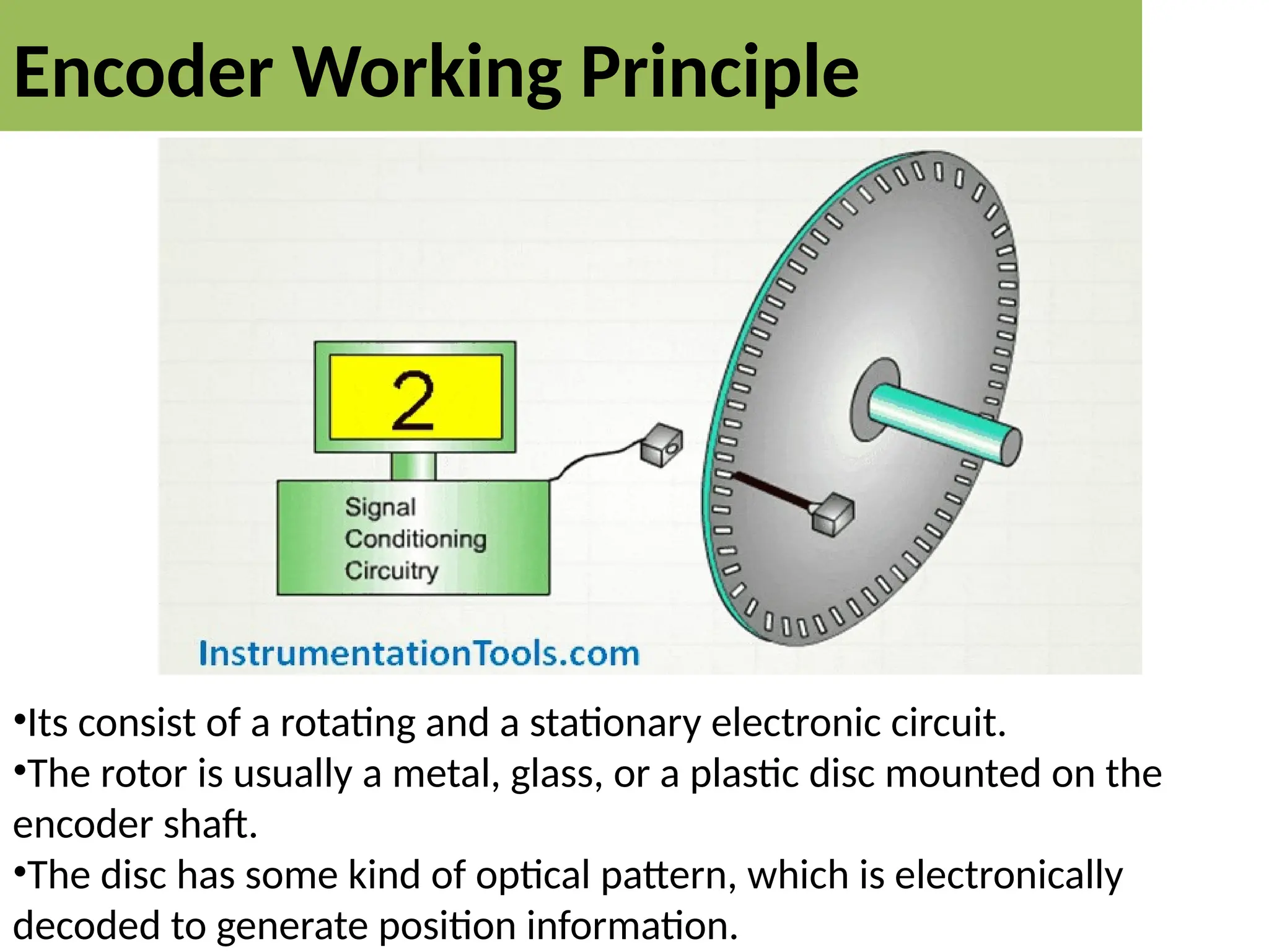
Encoder Working Principle
•Itsconsist of a rotating and a stationary electronic circuit.
•The rotor is usually a metal, glass, or a plastic disc mounted on the
encoder shaft.
•The disc has some kind of optical pattern, which is electronically
decoded to generate position information.
5.
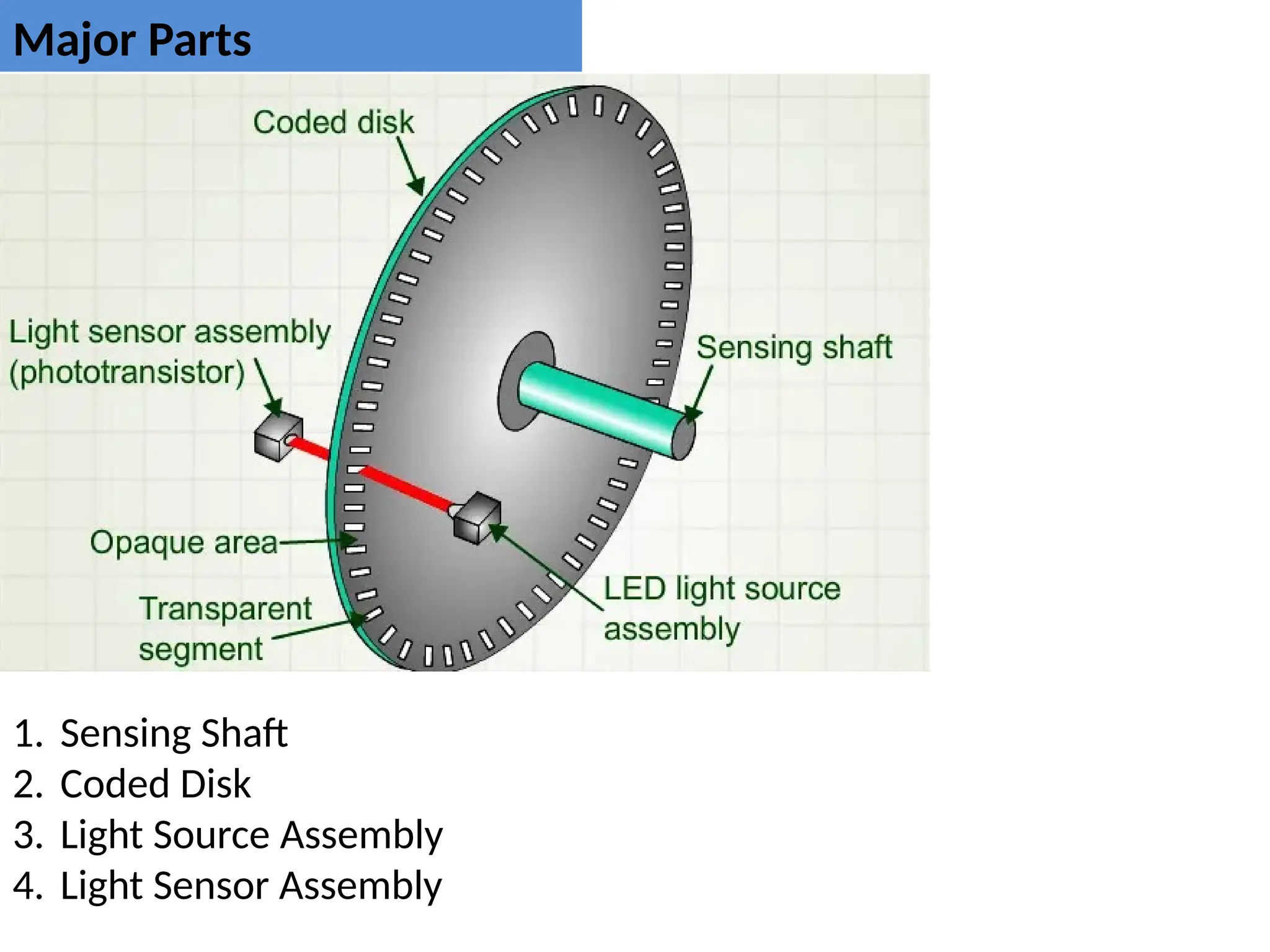
Major Parts
1. SensingShaft
2. Coded Disk
3. Light Source Assembly
4. Light Sensor Assembly
6.
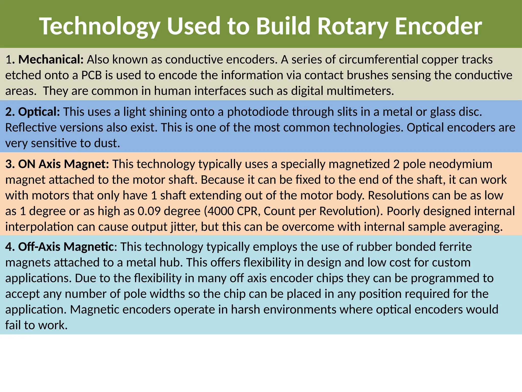
Technology Used toBuild Rotary Encoder
1. Mechanical: Also known as conductive encoders. A series of circumferential copper tracks
etched onto a PCB is used to encode the information via contact brushes sensing the conductive
areas. They are common in human interfaces such as digital multimeters.
2. Optical: This uses a light shining onto a photodiode through slits in a metal or glass disc.
Reflective versions also exist. This is one of the most common technologies. Optical encoders are
very sensitive to dust.
3. ON Axis Magnet: This technology typically uses a specially magnetized 2 pole neodymium
magnet attached to the motor shaft. Because it can be fixed to the end of the shaft, it can work
with motors that only have 1 shaft extending out of the motor body. Resolutions can be as low
as 1 degree or as high as 0.09 degree (4000 CPR, Count per Revolution). Poorly designed internal
interpolation can cause output jitter, but this can be overcome with internal sample averaging.
4. Off-Axis Magnetic: This technology typically employs the use of rubber bonded ferrite
magnets attached to a metal hub. This offers flexibility in design and low cost for custom
applications. Due to the flexibility in many off axis encoder chips they can be programmed to
accept any number of pole widths so the chip can be placed in any position required for the
application. Magnetic encoders operate in harsh environments where optical encoders would
fail to work.
7.
Type of RotaryEncoder
1. Incremental Encoder
2. Absolute Encoder
8.
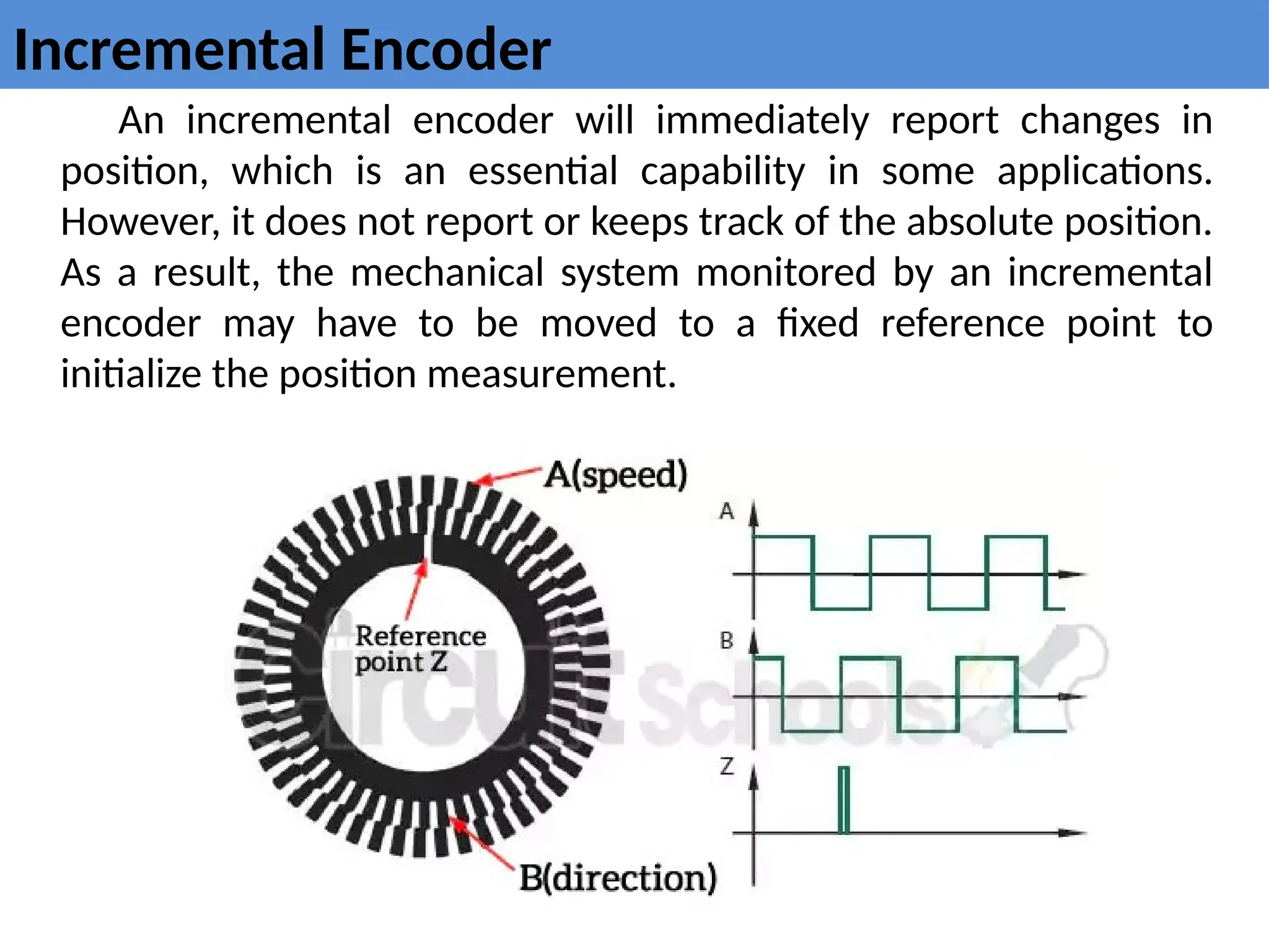
Incremental Encoder
An incrementalencoder will immediately report changes in
position, which is an essential capability in some applications.
However, it does not report or keeps track of the absolute position.
As a result, the mechanical system monitored by an incremental
encoder may have to be moved to a fixed reference point to
initialize the position measurement.
9.
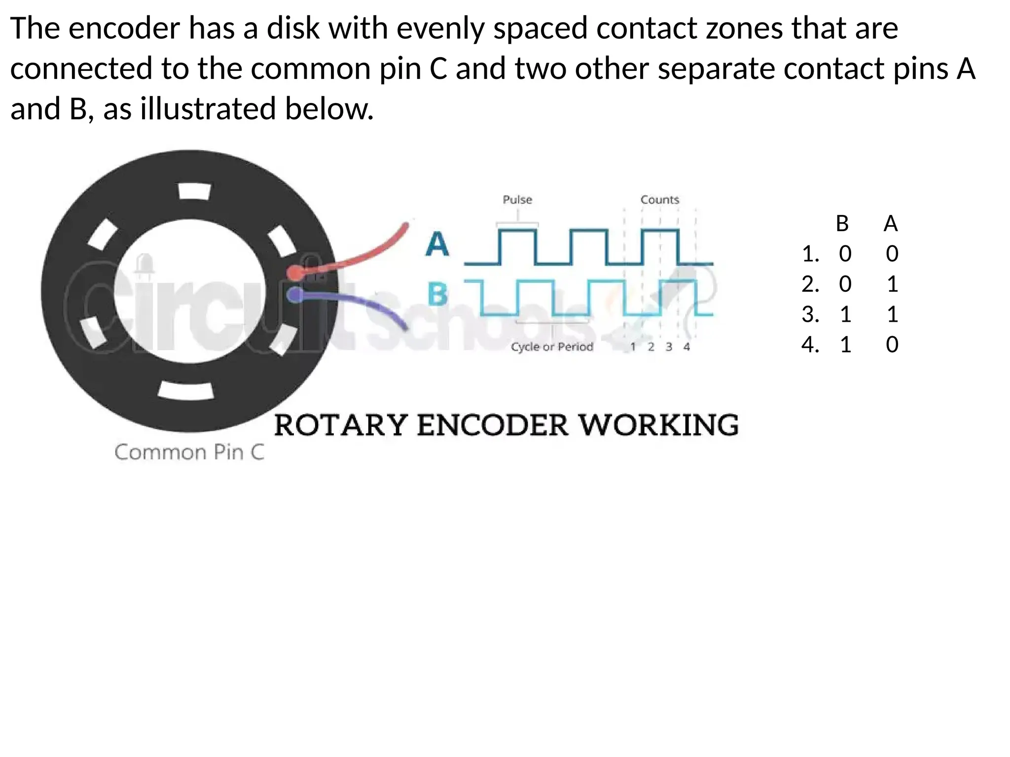
The encoder hasa disk with evenly spaced contact zones that are
connected to the common pin C and two other separate contact pins A
and B, as illustrated below.
B A
1. 0 0
2. 0 1
3. 1 1
4. 1 0
10.
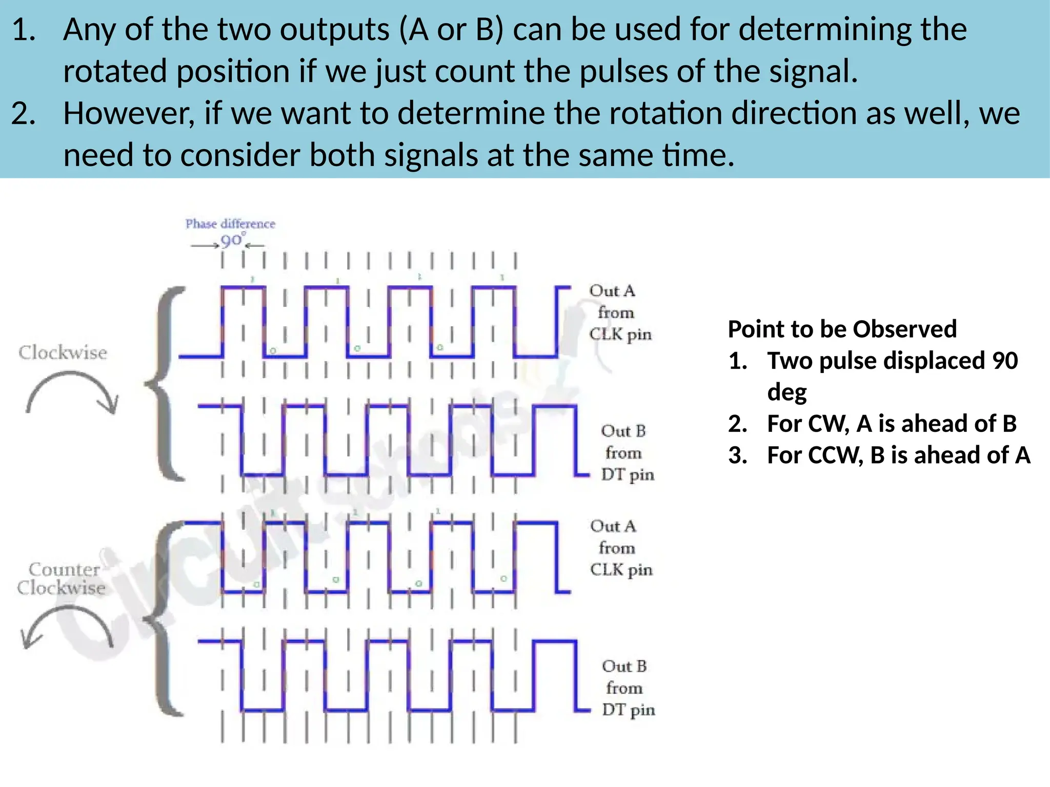
1. Any ofthe two outputs (A or B) can be used for determining the
rotated position if we just count the pulses of the signal.
2. However, if we want to determine the rotation direction as well, we
need to consider both signals at the same time.
Point to be Observed
1. Two pulse displaced 90
deg
2. For CW, A is ahead of B
3. For CCW, B is ahead of A
11.
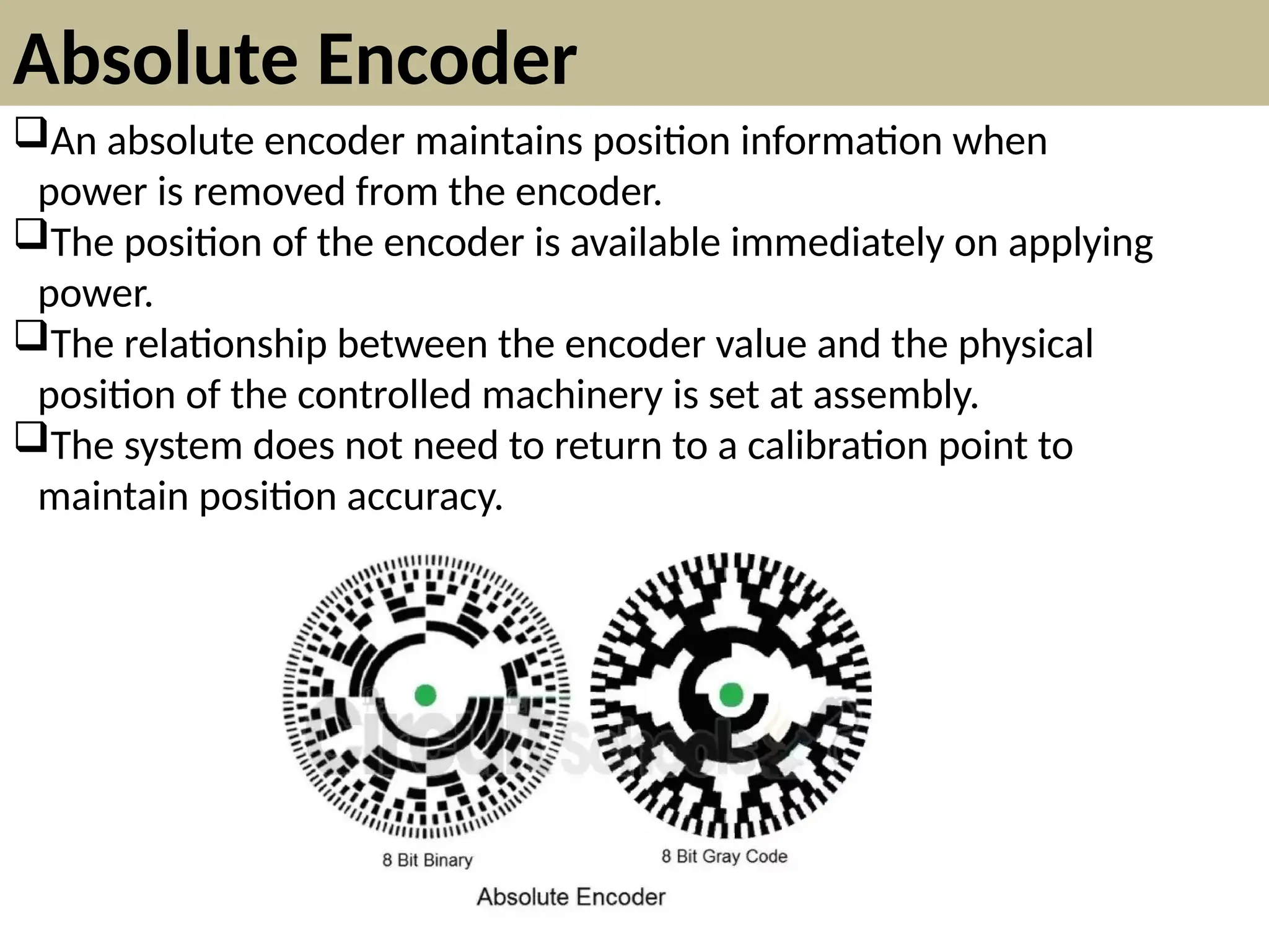
Absolute Encoder
An absoluteencoder maintains position information when
power is removed from the encoder.
The position of the encoder is available immediately on applying
power.
The relationship between the encoder value and the physical
position of the controlled machinery is set at assembly.
The system does not need to return to a calibration point to
maintain position accuracy.
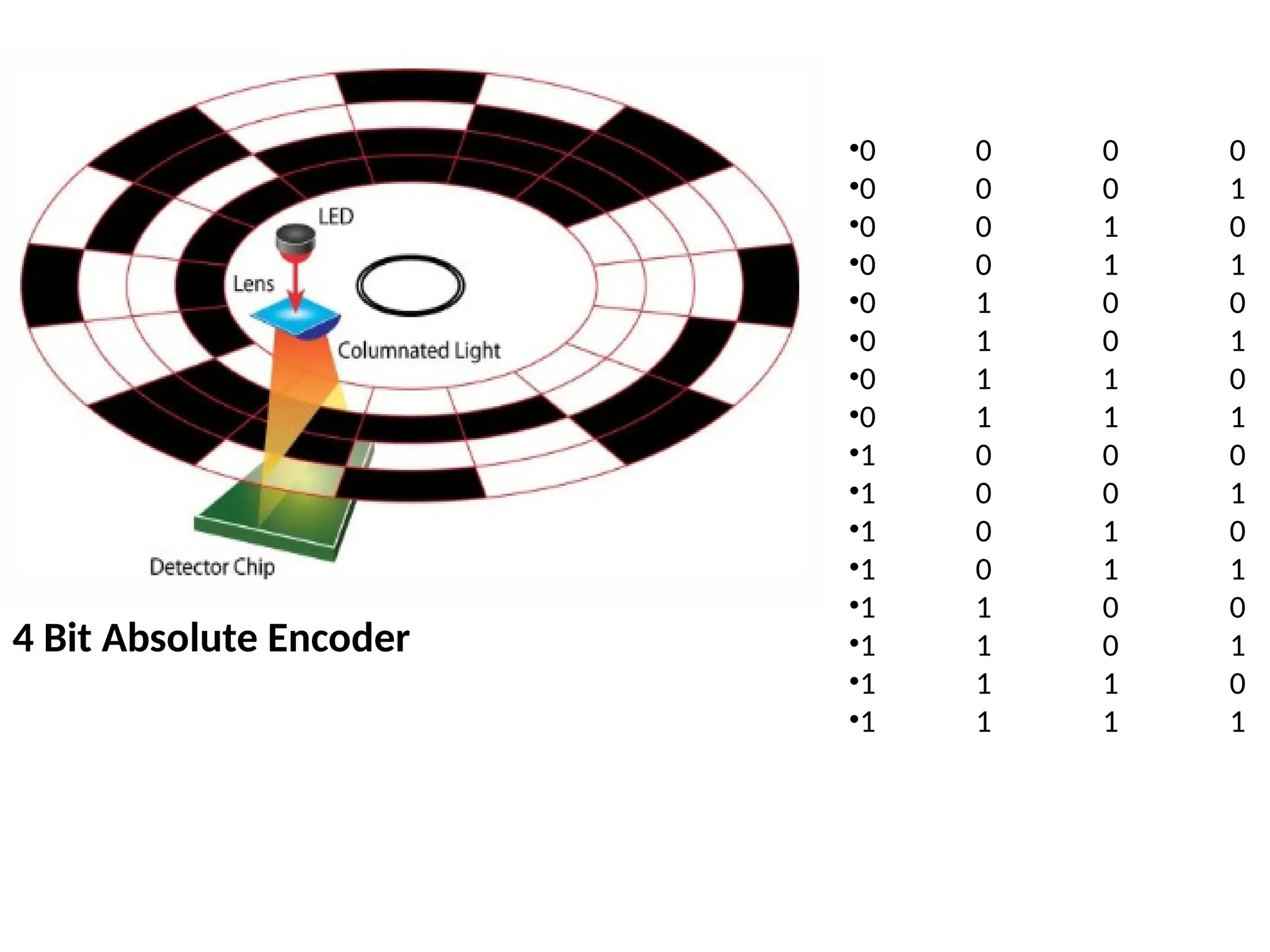
12.
An absolute encoderhas multiple code rings with various binary
weightings which provide a data word representing the absolute
position of the encoder within one revolution. This type of encoder is
often referred to as a parallel absolute encoder.
A multi-turn absolute rotary encoder includes additional code wheels
and gears. A high-resolution wheel measures the fractional rotation, and
lower-resolution geared code wheels record the number of whole
revolutions of the shaft.
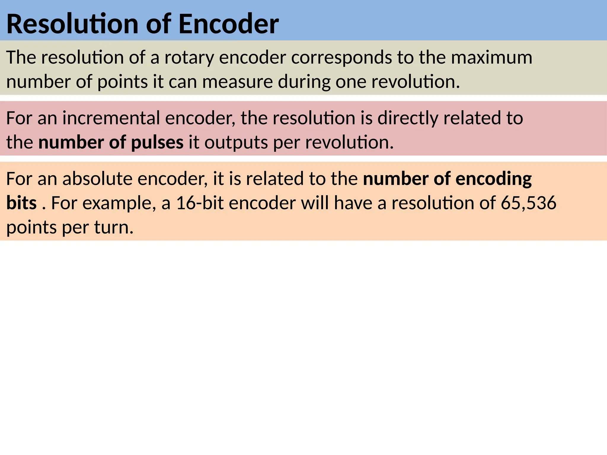
Resolution of Encoder
Theresolution of a rotary encoder corresponds to the maximum
number of points it can measure during one revolution.
For an incremental encoder, the resolution is directly related to
the number of pulses it outputs per revolution.
For an absolute encoder, it is related to the number of encoding
bits . For example, a 16-bit encoder will have a resolution of 65,536
points per turn.
15.
Application of Encoder
1.Door control devices.
2. robots.
3. Lens beveling machines.
4. plotters.
5. Testing machines.
6. Ultrasonic welding.
7. Warping machines and medical technical equipment.
8. Parts assembly machines.
9. Labeling machines.
10.Graphical displays of X and Y axes.
11.Analysis systems.
12.Drilling machines.
13.Mixing machines.
16.
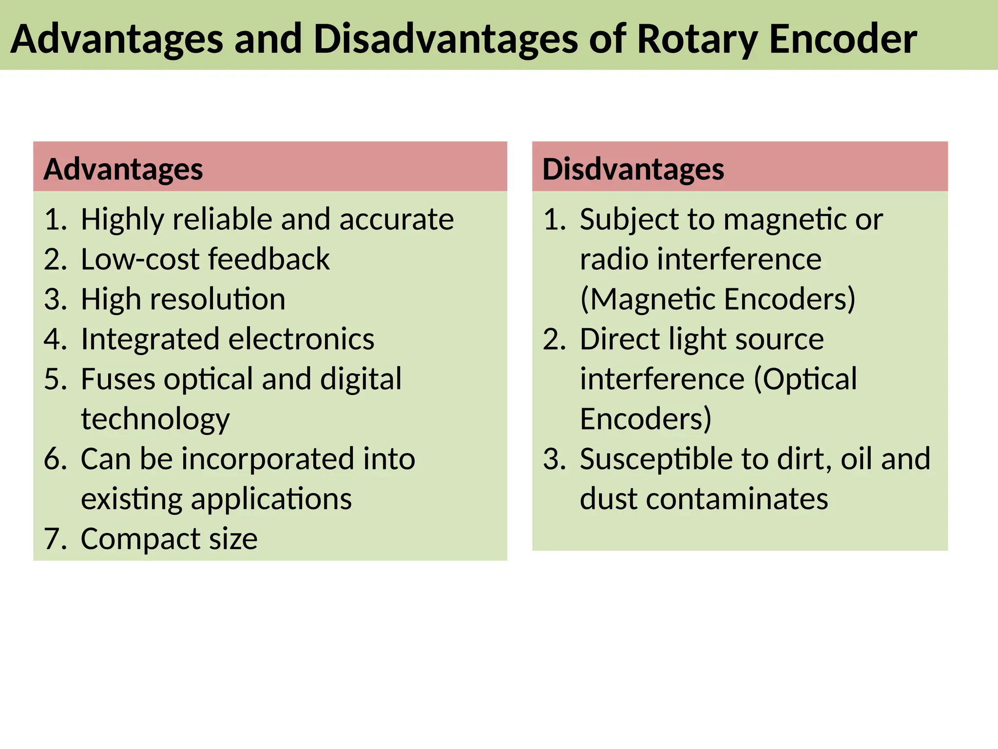
Advantages and Disadvantagesof Rotary Encoder
1. Highly reliable and accurate
2. Low-cost feedback
3. High resolution
4. Integrated electronics
5. Fuses optical and digital
technology
6. Can be incorporated into
existing applications
7. Compact size
1. Subject to magnetic or
radio interference
(Magnetic Encoders)
2. Direct light source
interference (Optical
Encoders)
3. Susceptible to dirt, oil and
dust contaminates
Advantages Disdvantages
17.
Selection Guide
• [1]IncrementalEncoder or Absolute Encoder?
• [2] How much resolution is needed?
• [3] Dimensions
• [4] Permitted Shaft Loading
• [5] Maximum Permissible Speed
• [6] Maximum Response Frequency
• [7] Degree of Protection
• [8] Startup Torque of Shaft
• [9] Output Circuit Type

![Selection Guide
• [1]Incremental Encoder or Absolute Encoder?
• [2] How much resolution is needed?
• [3] Dimensions
• [4] Permitted Shaft Loading
• [5] Maximum Permissible Speed
• [6] Maximum Response Frequency
• [7] Degree of Protection
• [8] Startup Torque of Shaft
• [9] Output Circuit Type](https://image.slidesharecdn.com/encoder-250921032704-bcc70153/75/encoder-of-servo-drive-required-for-movement-17-2048.jpg)