Download as PDF, PPTX
![Information on specific files can be viewed as follows (filename of IOS shown in the
example)…
6500# show file info disk0:s72033-ps-mz.122-14.SX1.bin
disk0:s72033-ps-mz.122-14.SX1.bin:
type is image (elf) []
file size is 26672876 bytes, run size is 26837656 bytes
Runnable image, entry point 0x80020000, run from ram
6500#
6500# dir disk0:
Directory of disk0:/
1 -rw- 26672876 Sep 09 2003 23:13:50 s72033-ps-mz.122-14.SX1.bin
256417792 bytes total (229744640 bytes free)](https://image.slidesharecdn.com/f8d8c998-18f8-44c0-b9d2-a4538c6bff2c-150426124452-conversion-gate02/85/Cisco-6500-v1-0-R-15-320.jpg)
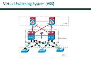
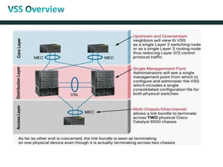
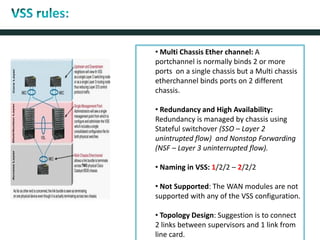
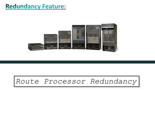
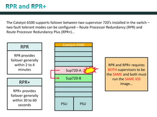
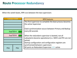
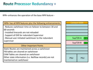
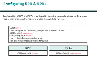
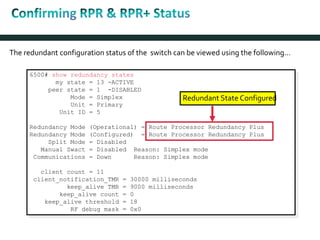
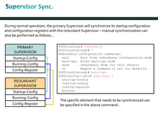
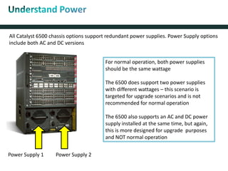
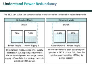
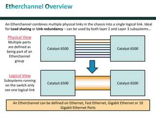
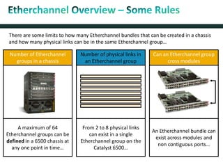
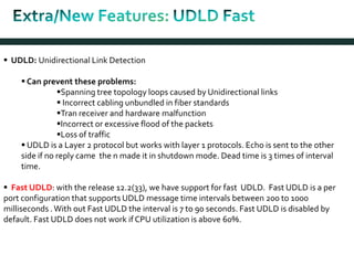
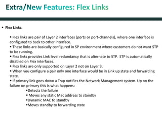
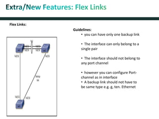
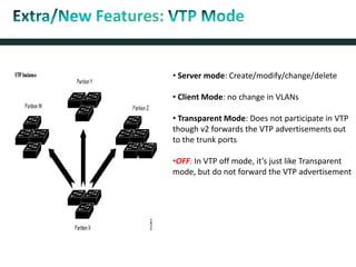
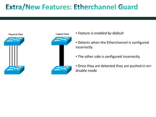

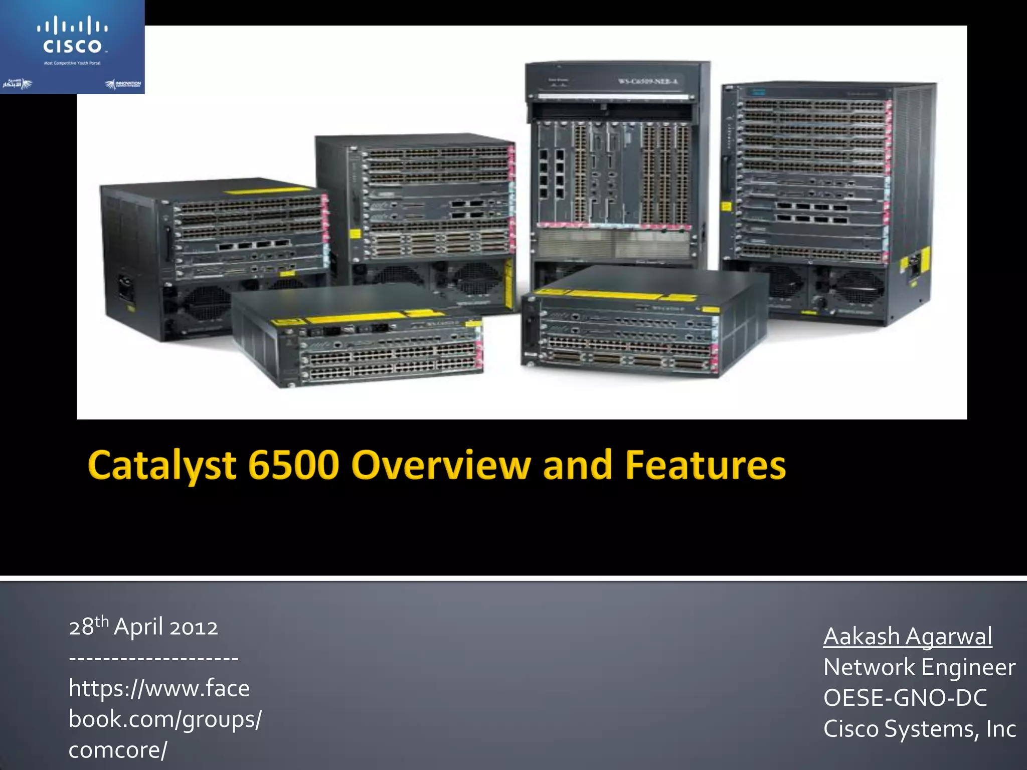
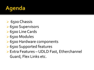
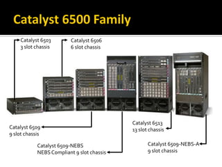
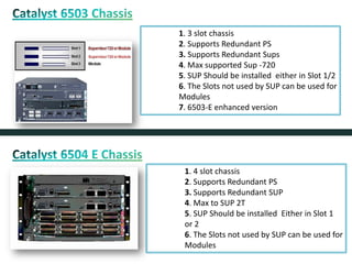
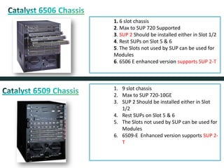
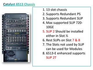
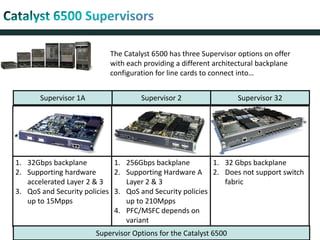
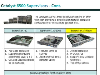
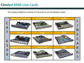
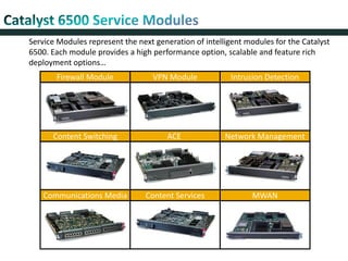
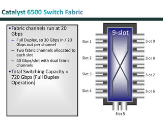
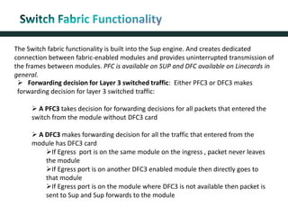
The document discusses the Cisco Catalyst 6500 series chassis and components. It provides details on the different chassis models, supervisor engines, line cards, and modules available. It also covers features like redundant power supplies, Route Processor Redundancy, EtherChannels, Unidirectional Link Detection, and Flex Links.


