Downloaded 237 times

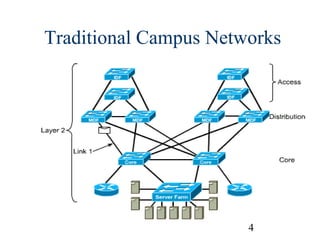
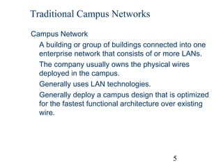
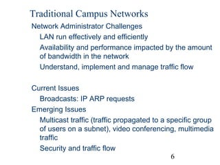
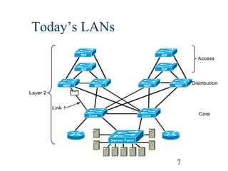
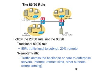
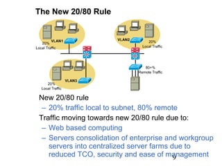
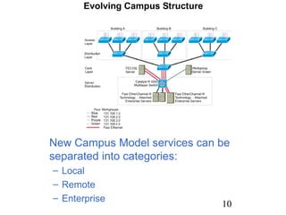
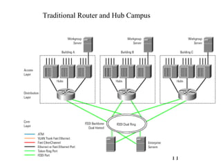
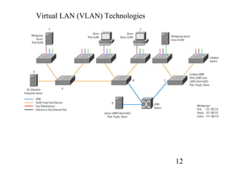
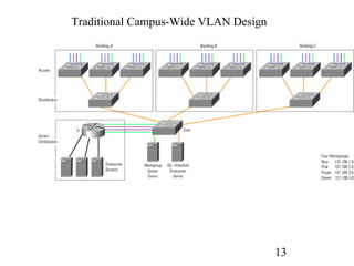
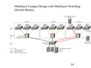
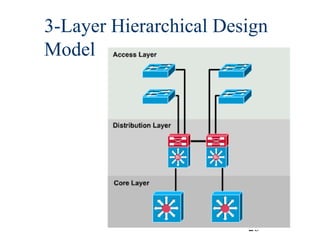
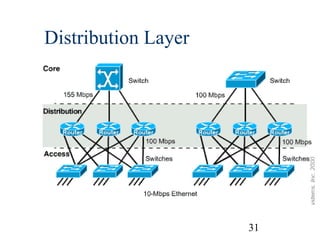
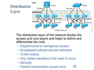
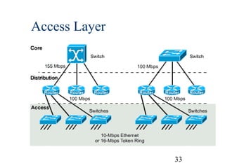
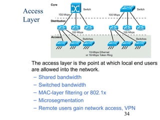
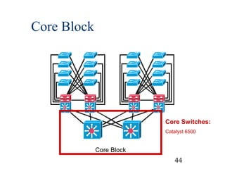
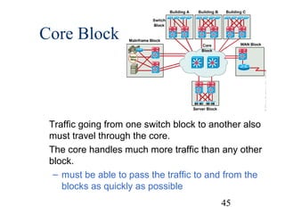
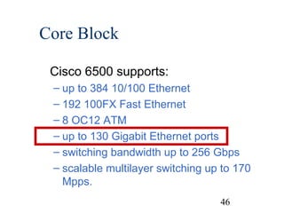

The document provides an overview of traditional campus network designs and introduces some concepts for campus network design. It discusses traditional router and hub campus designs and moves to newer designs using virtual LAN (VLAN) technologies and multilayer switching. The key concepts covered include the access, distribution and core layers, switch blocks, core blocks, and considerations around sizing and redundancy in campus network designs.