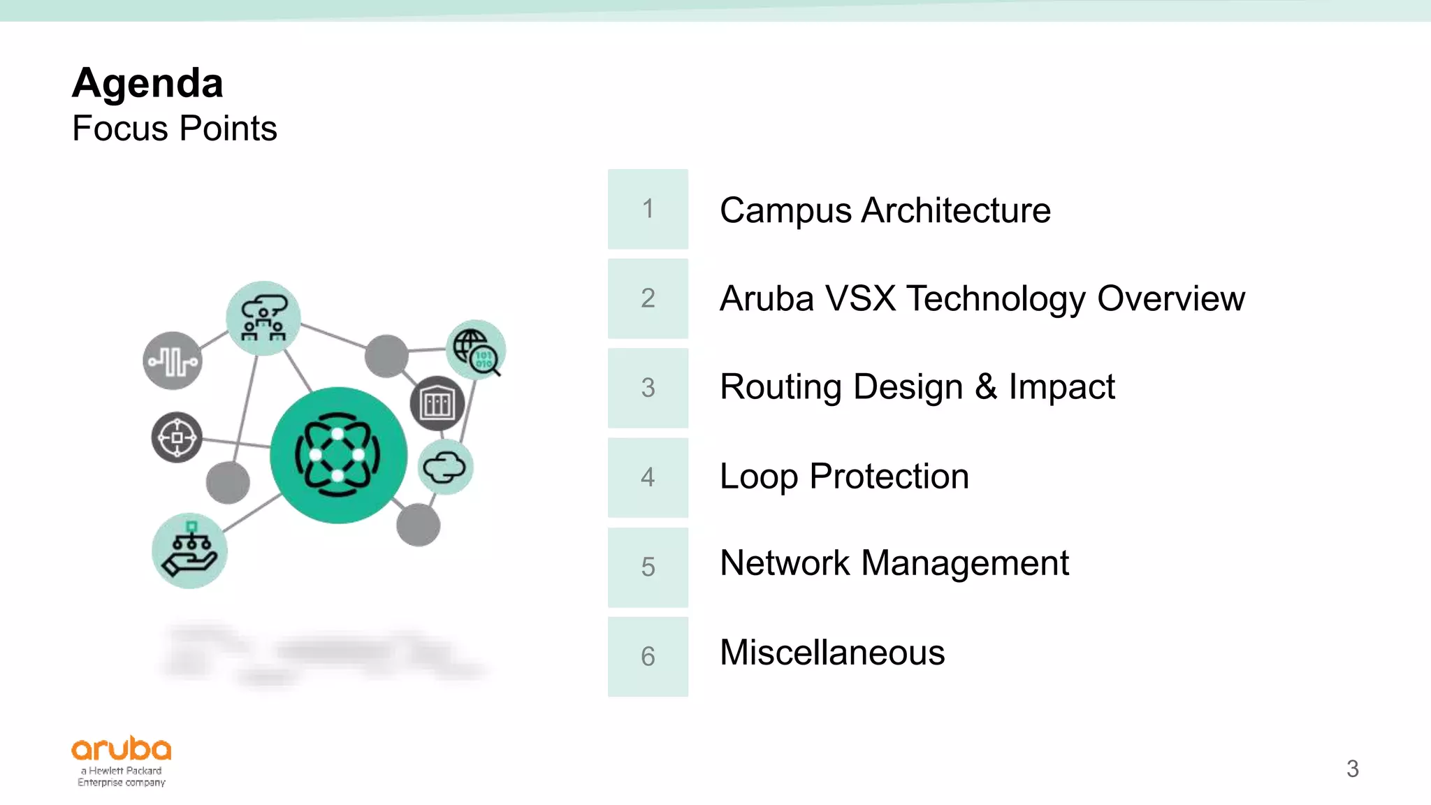
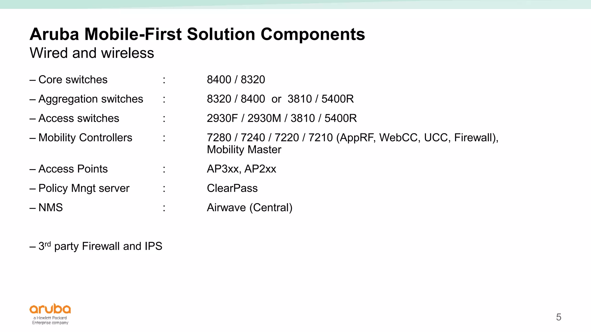
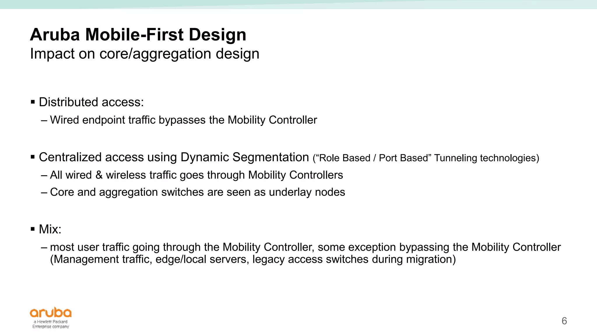
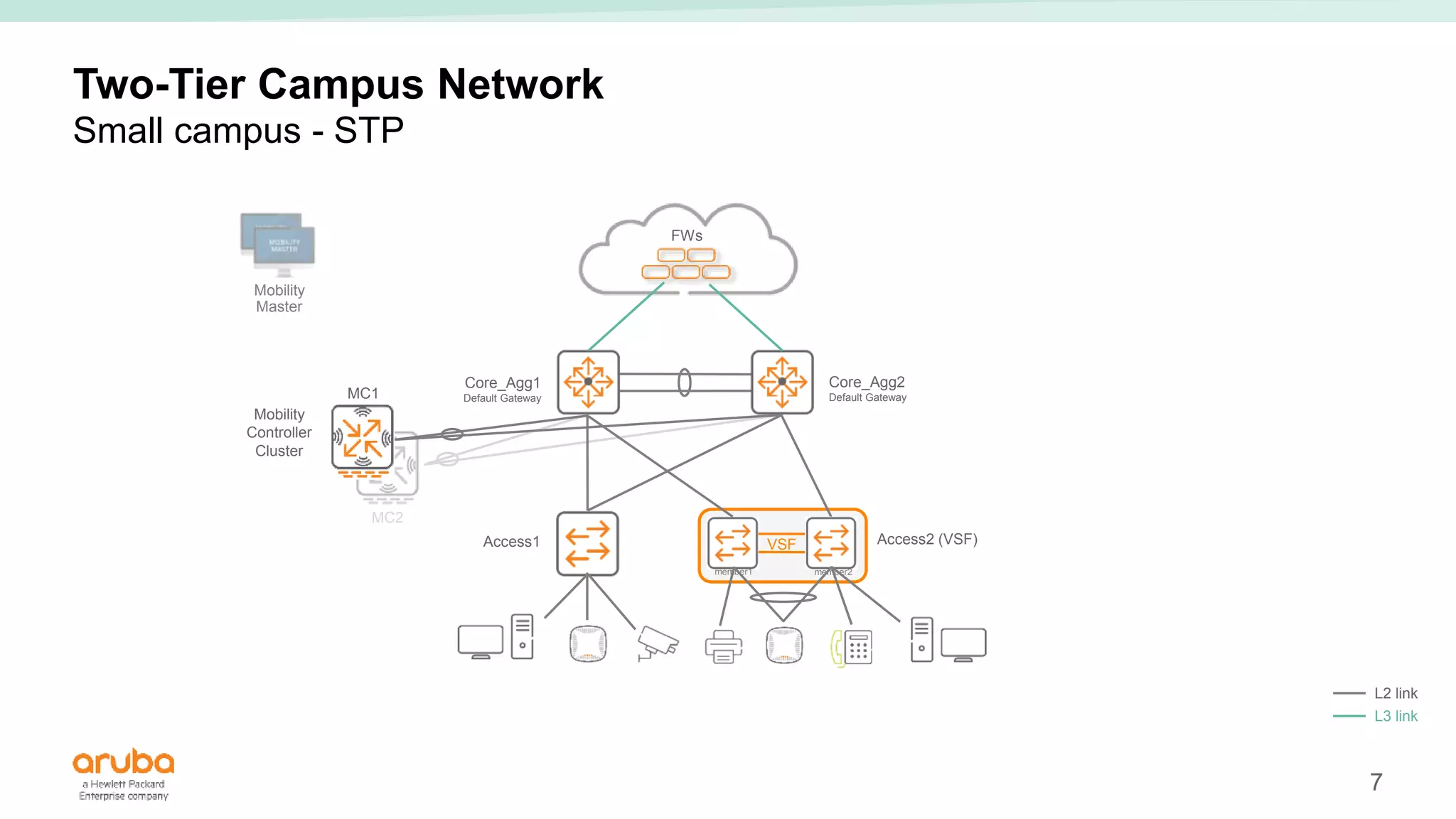
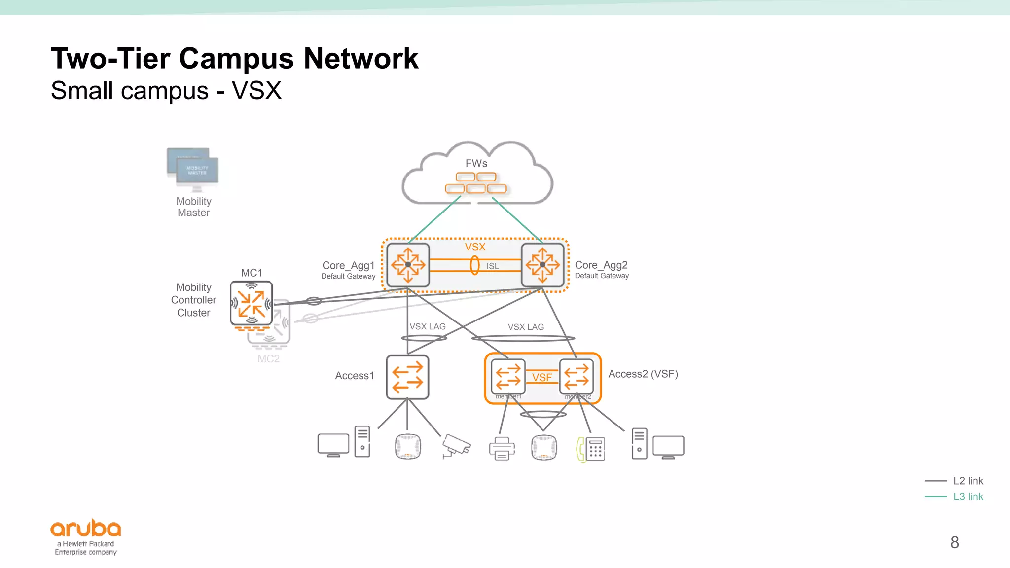
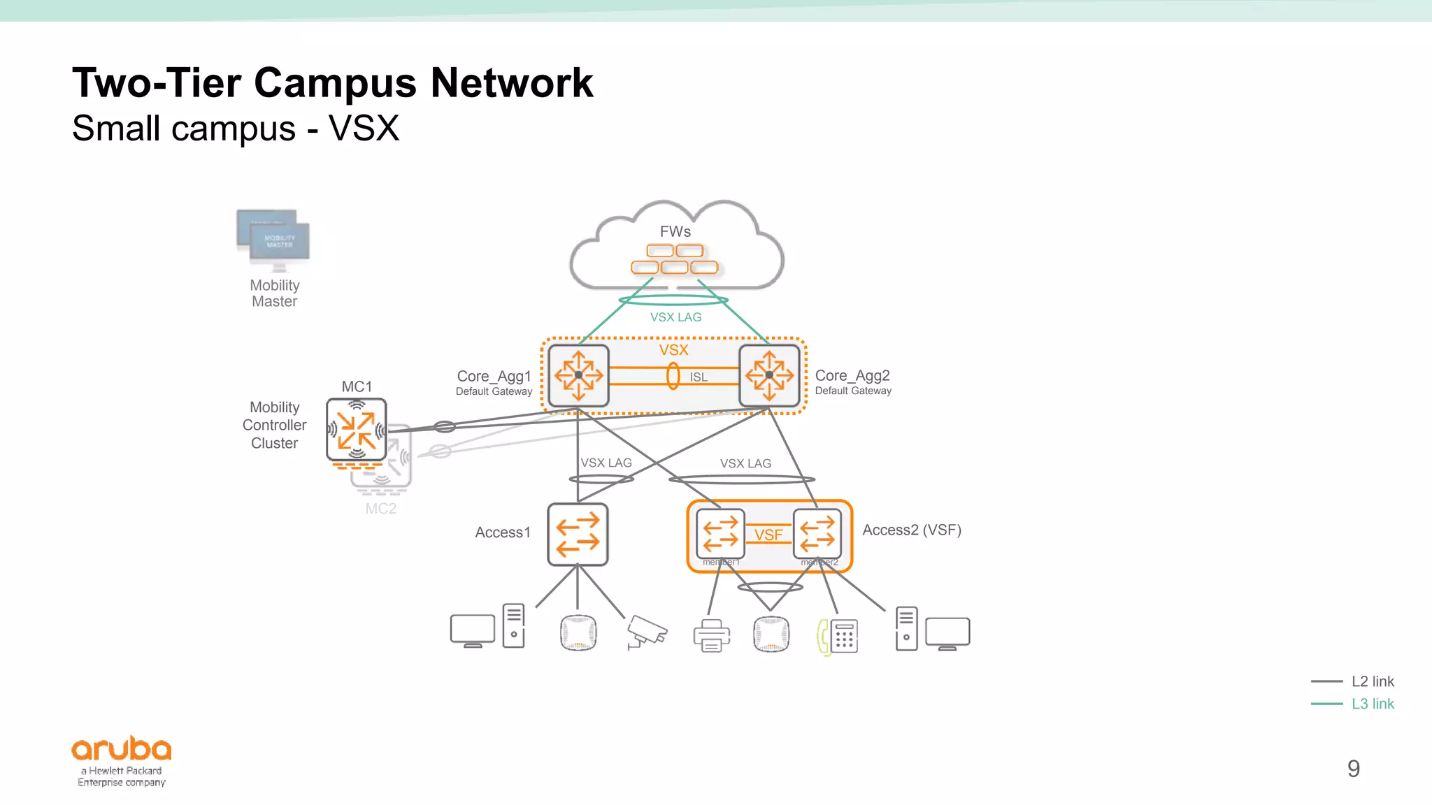
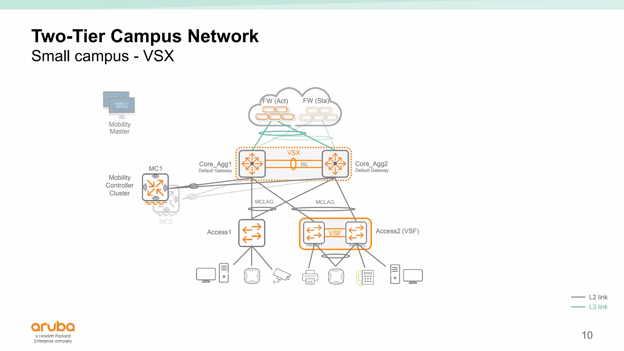
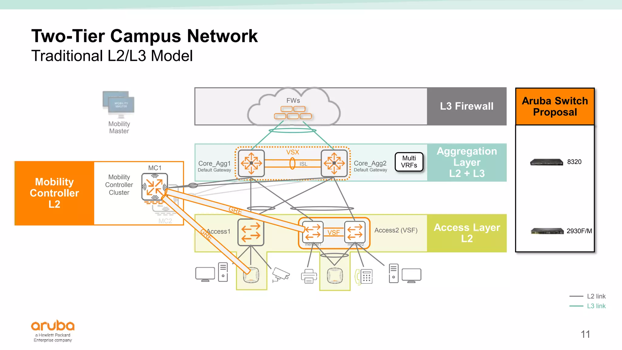
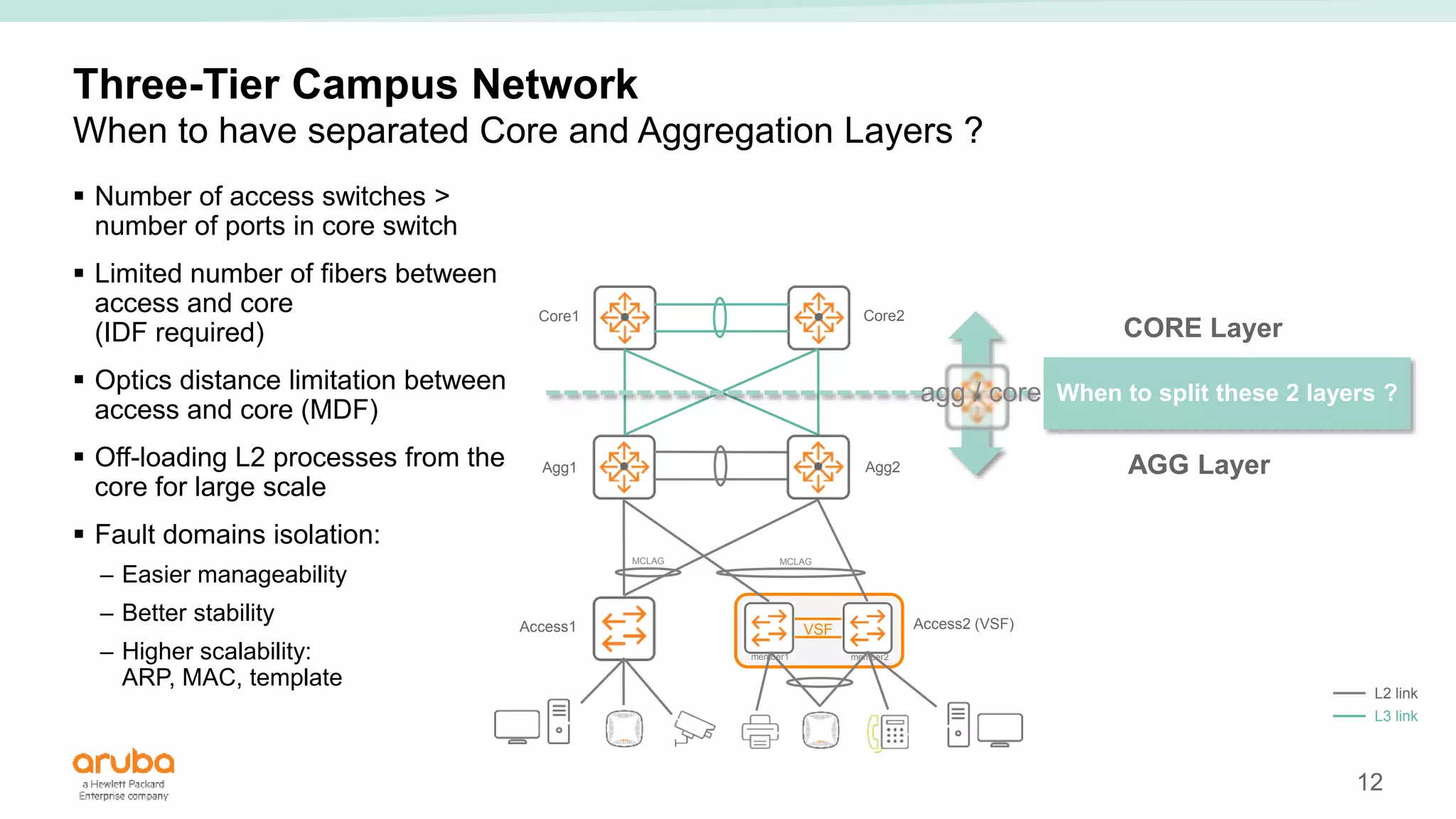
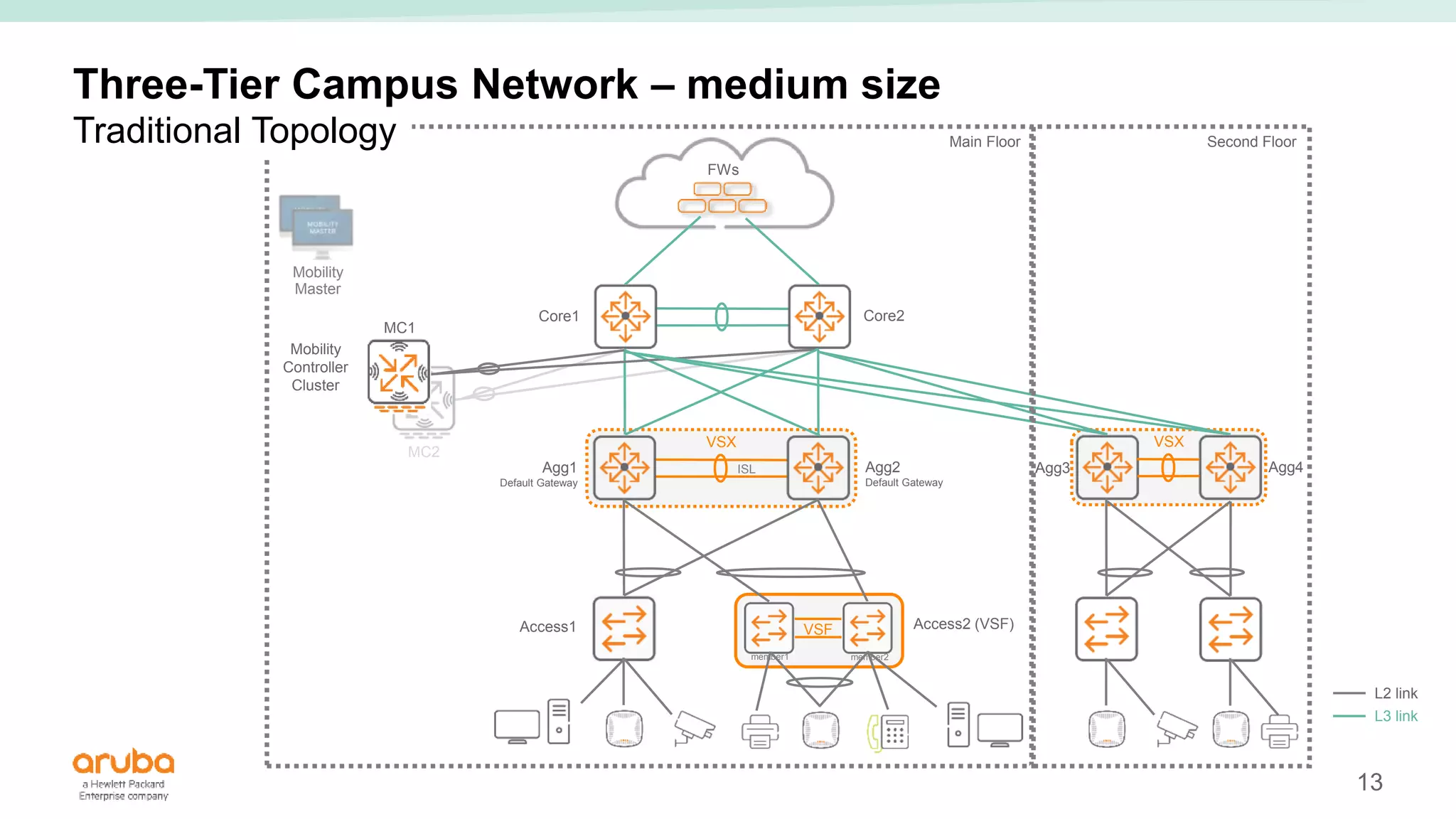
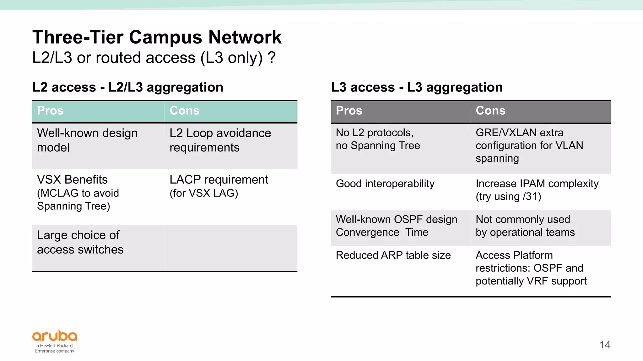
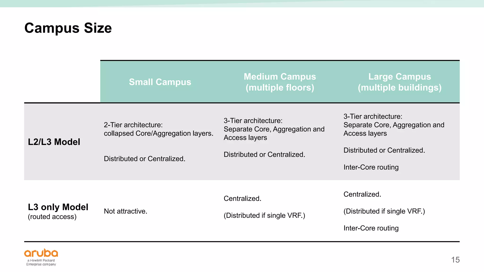
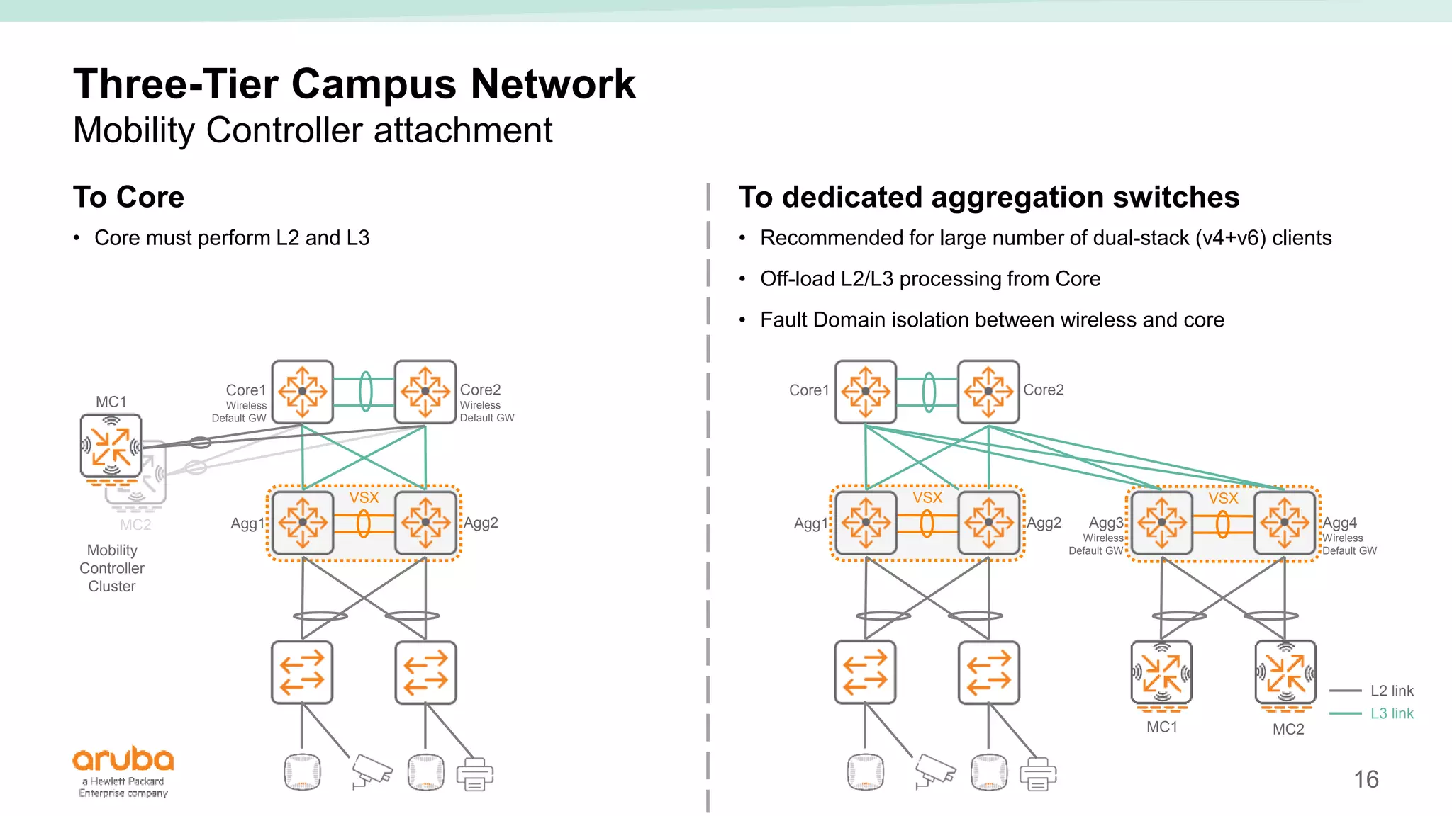
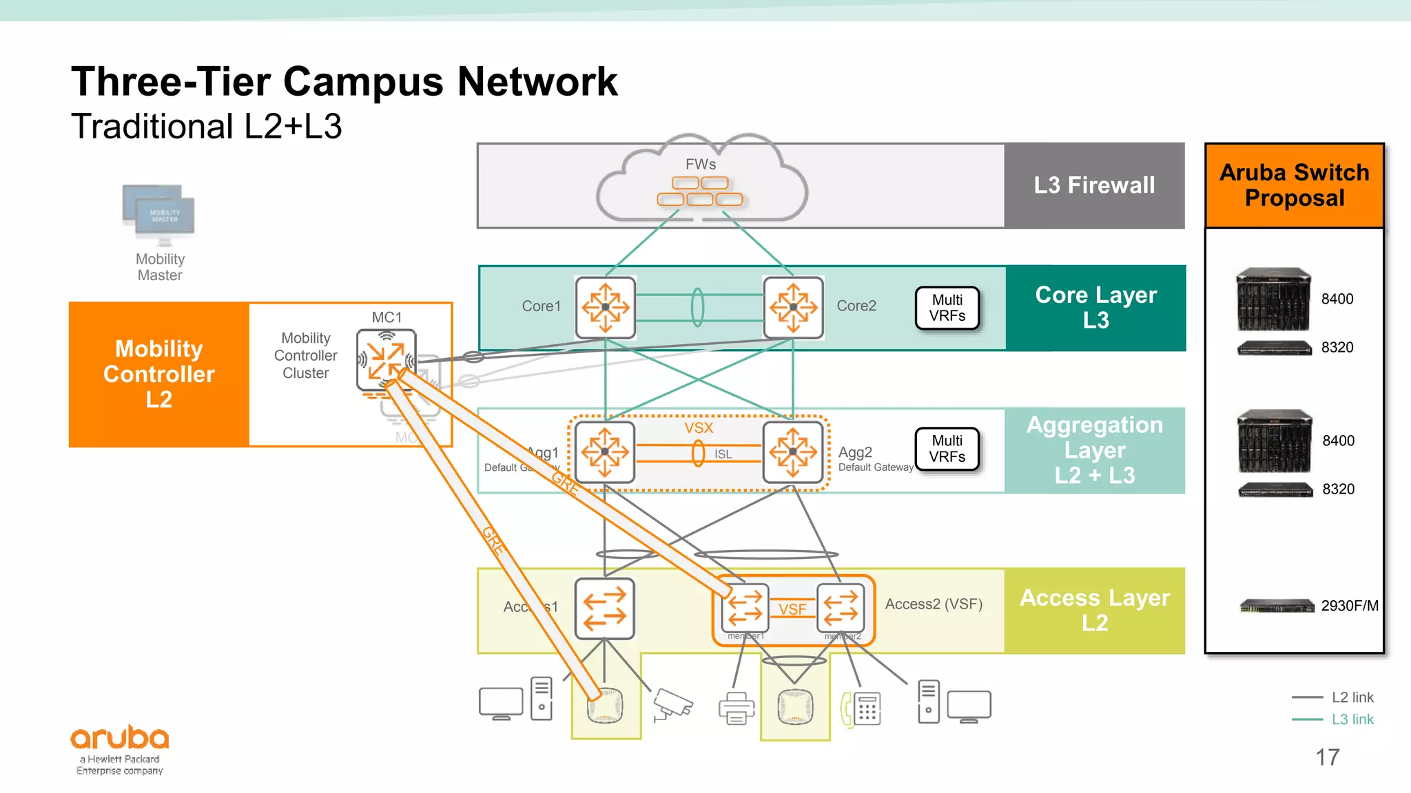
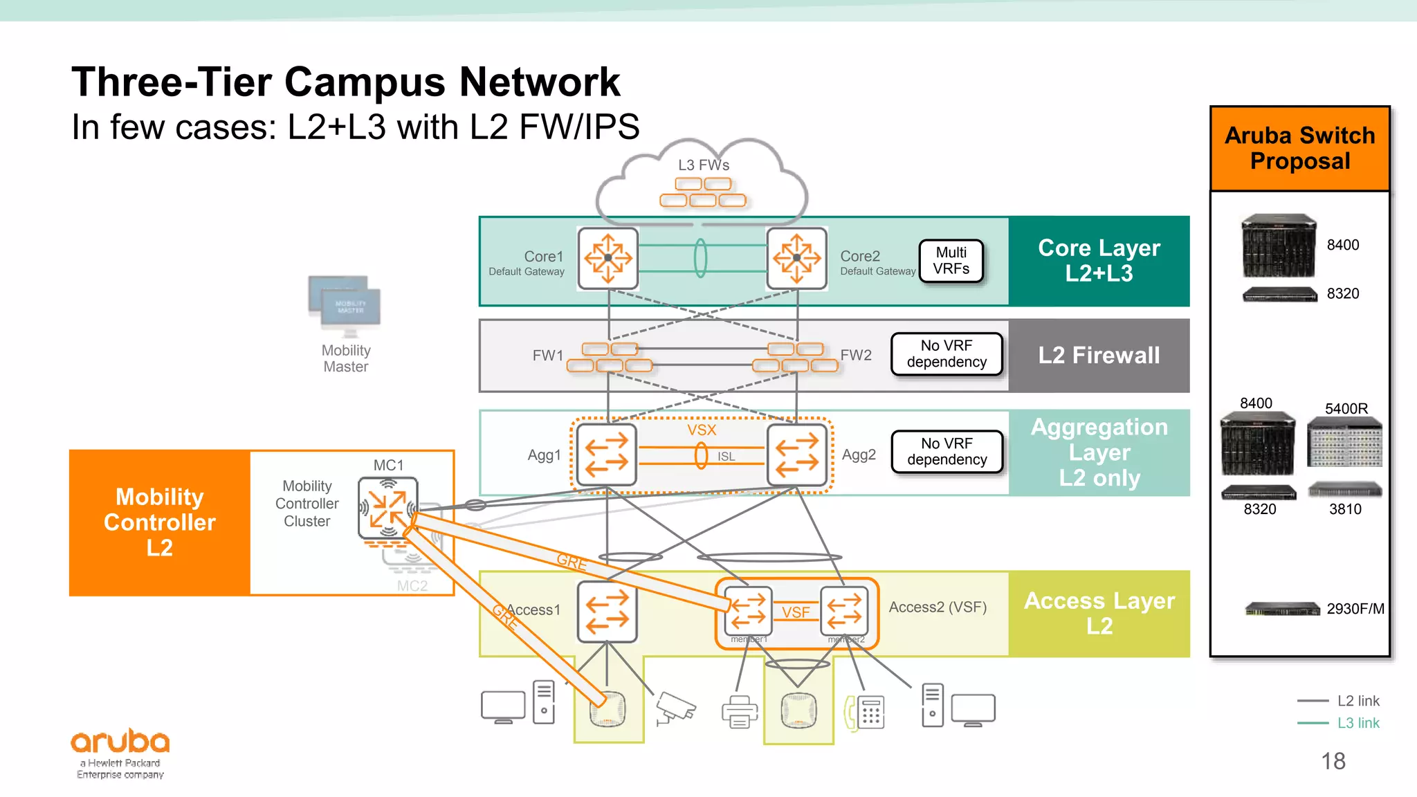
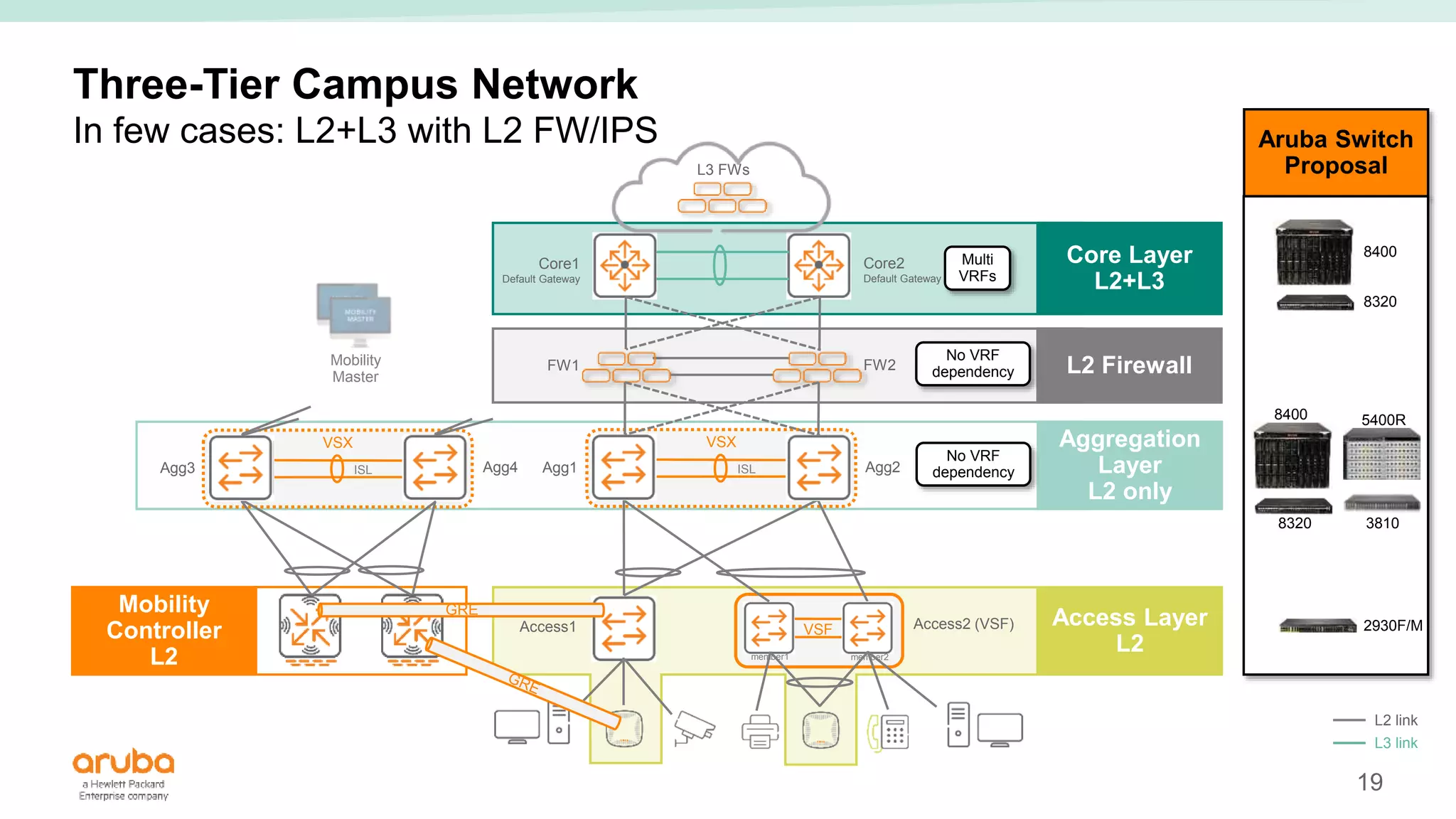
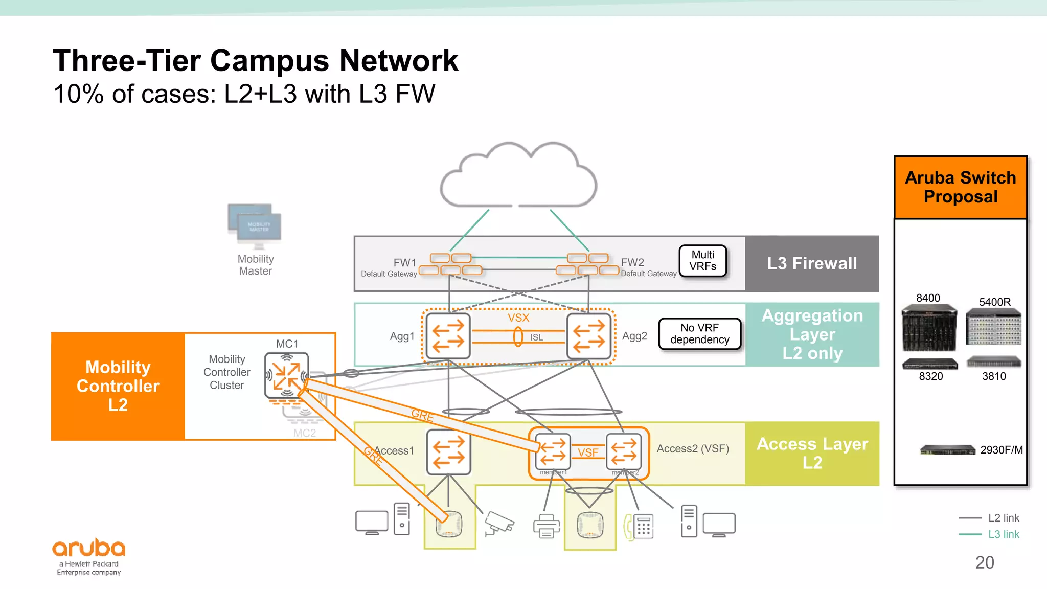
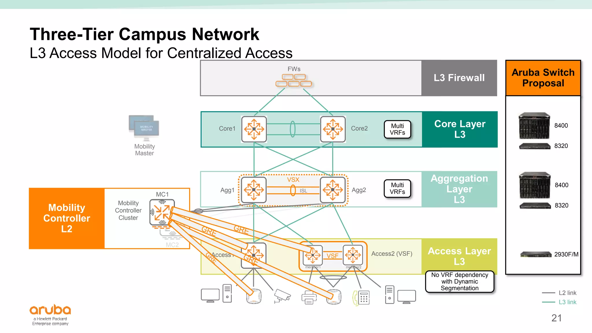
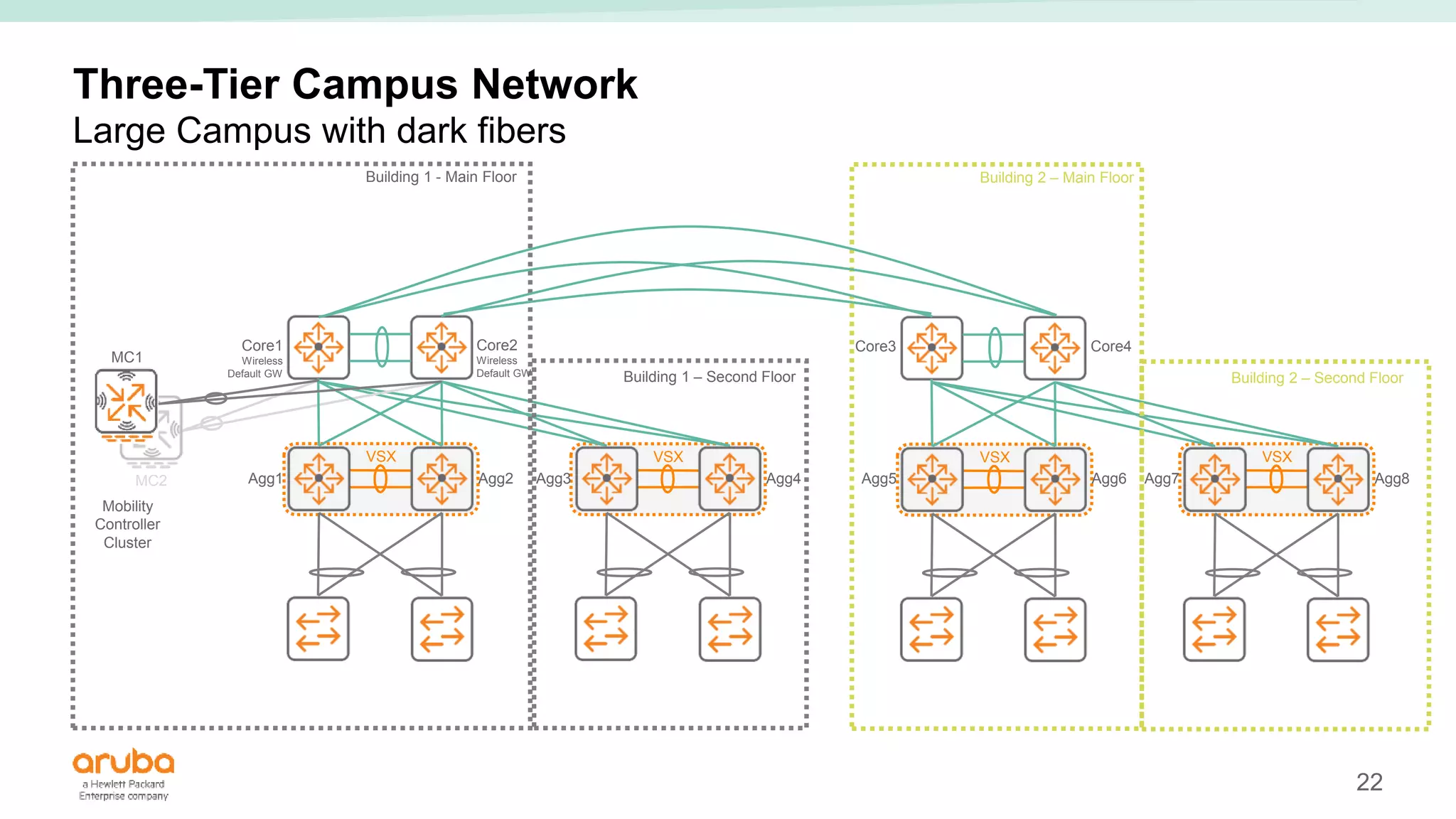
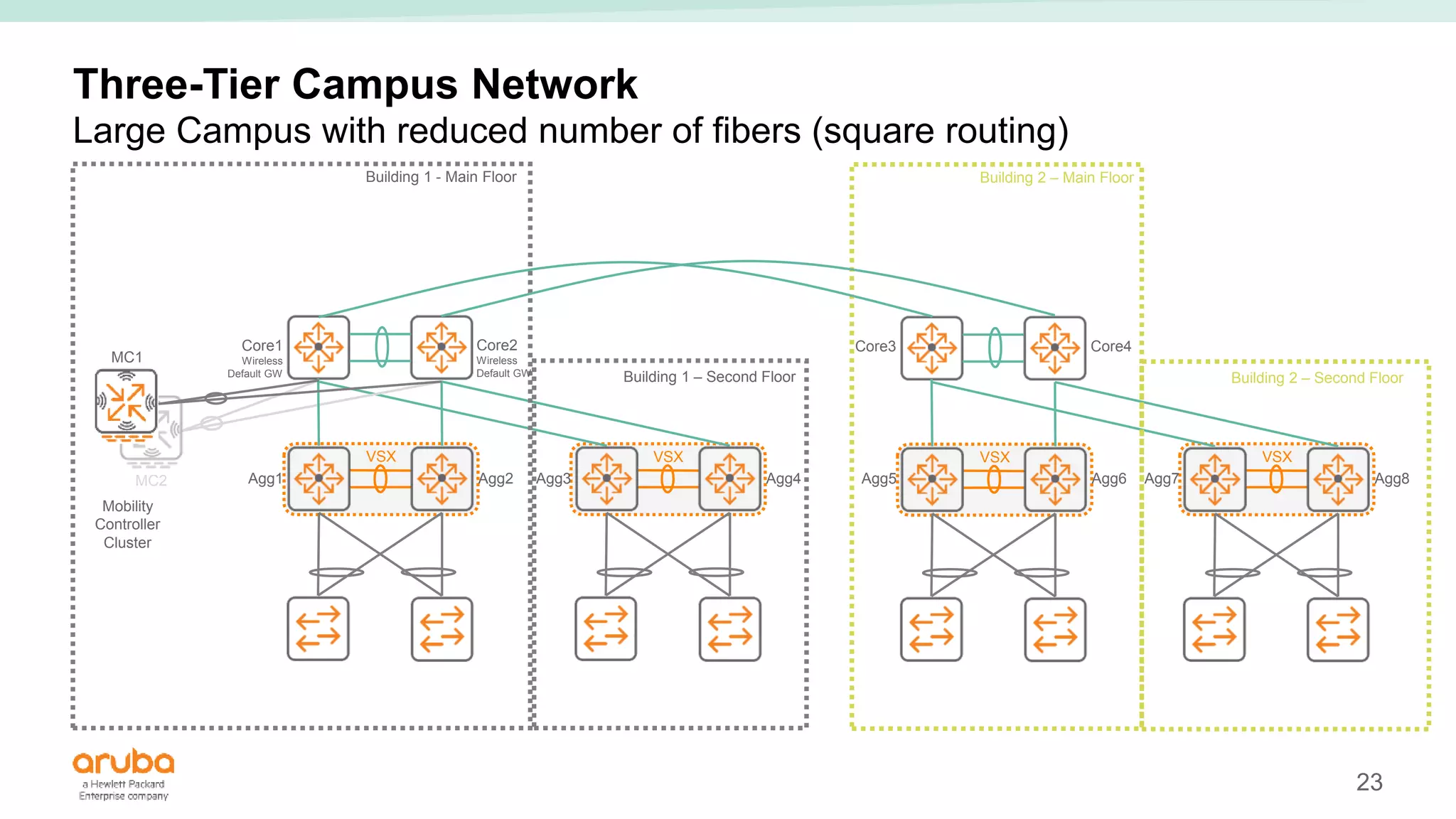
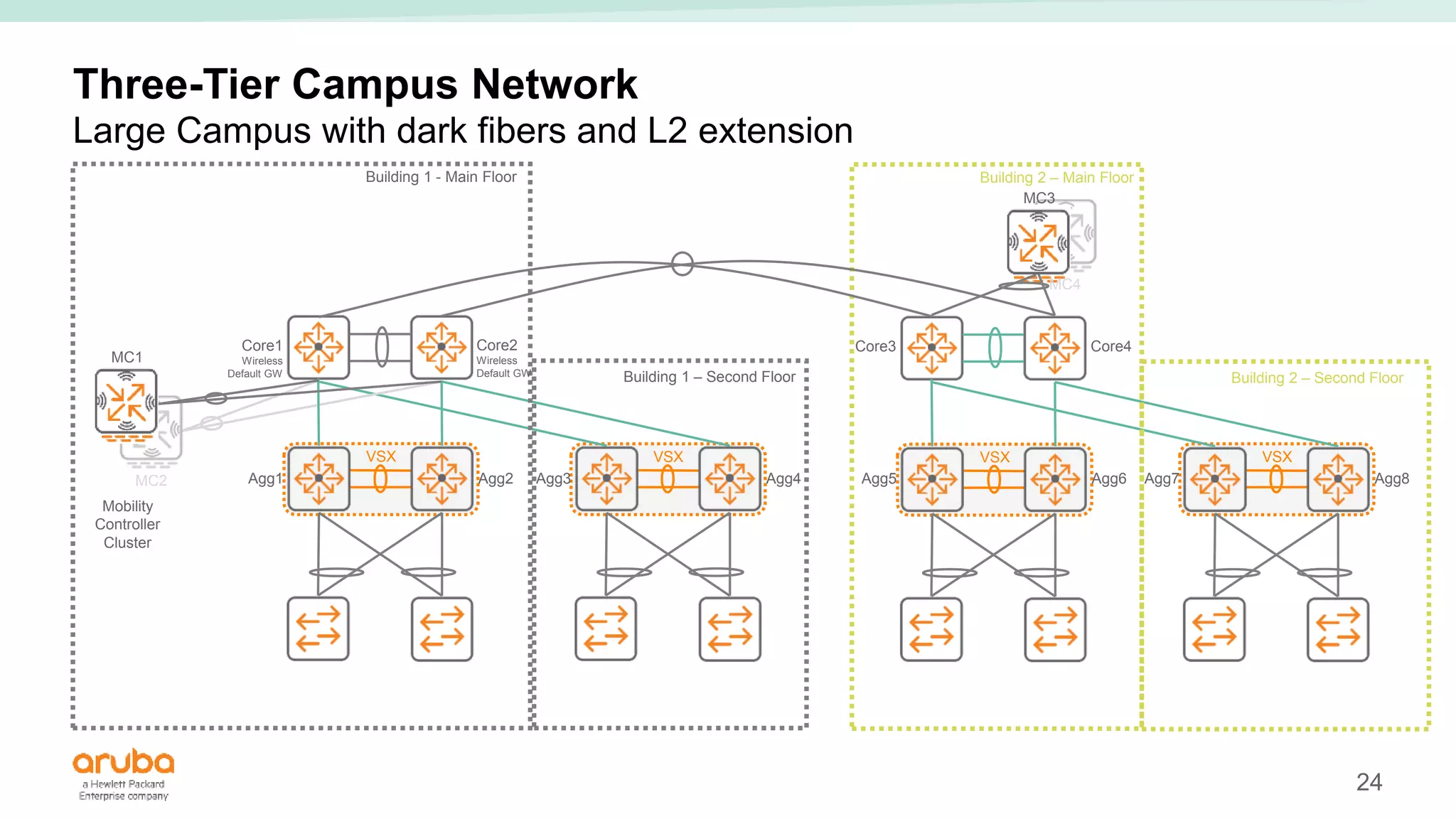
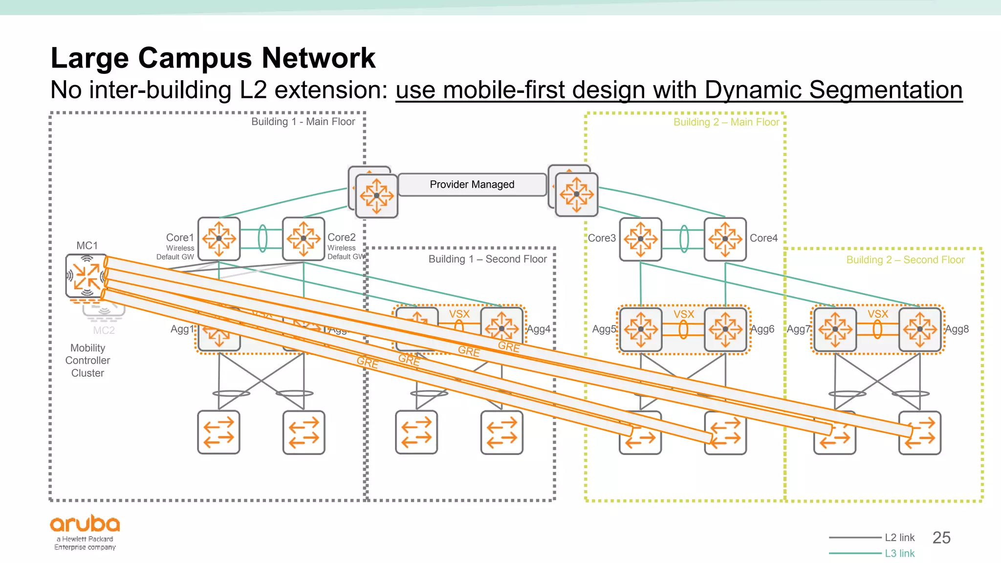
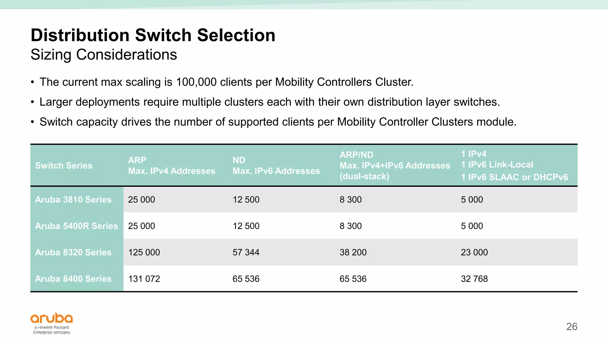
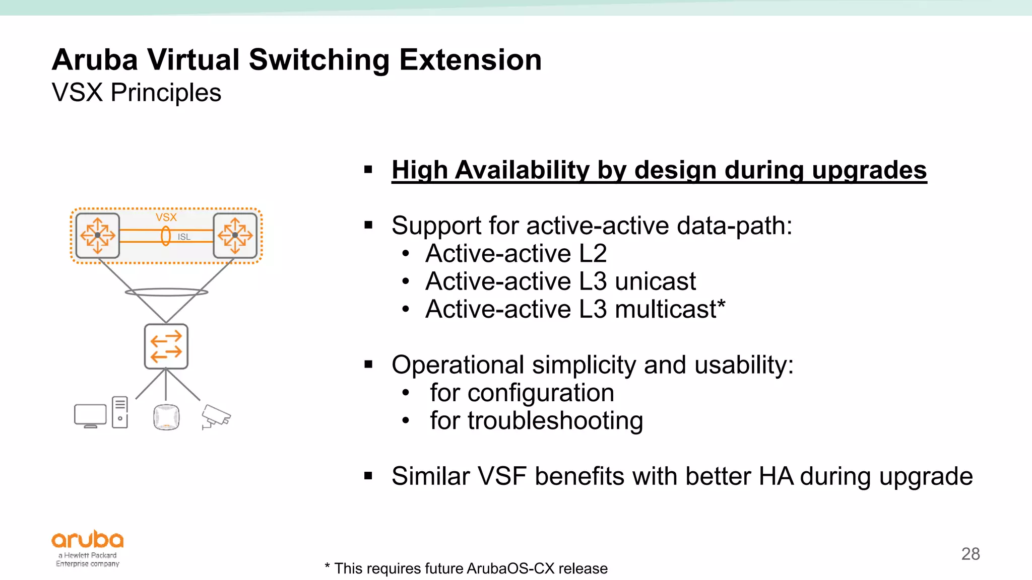
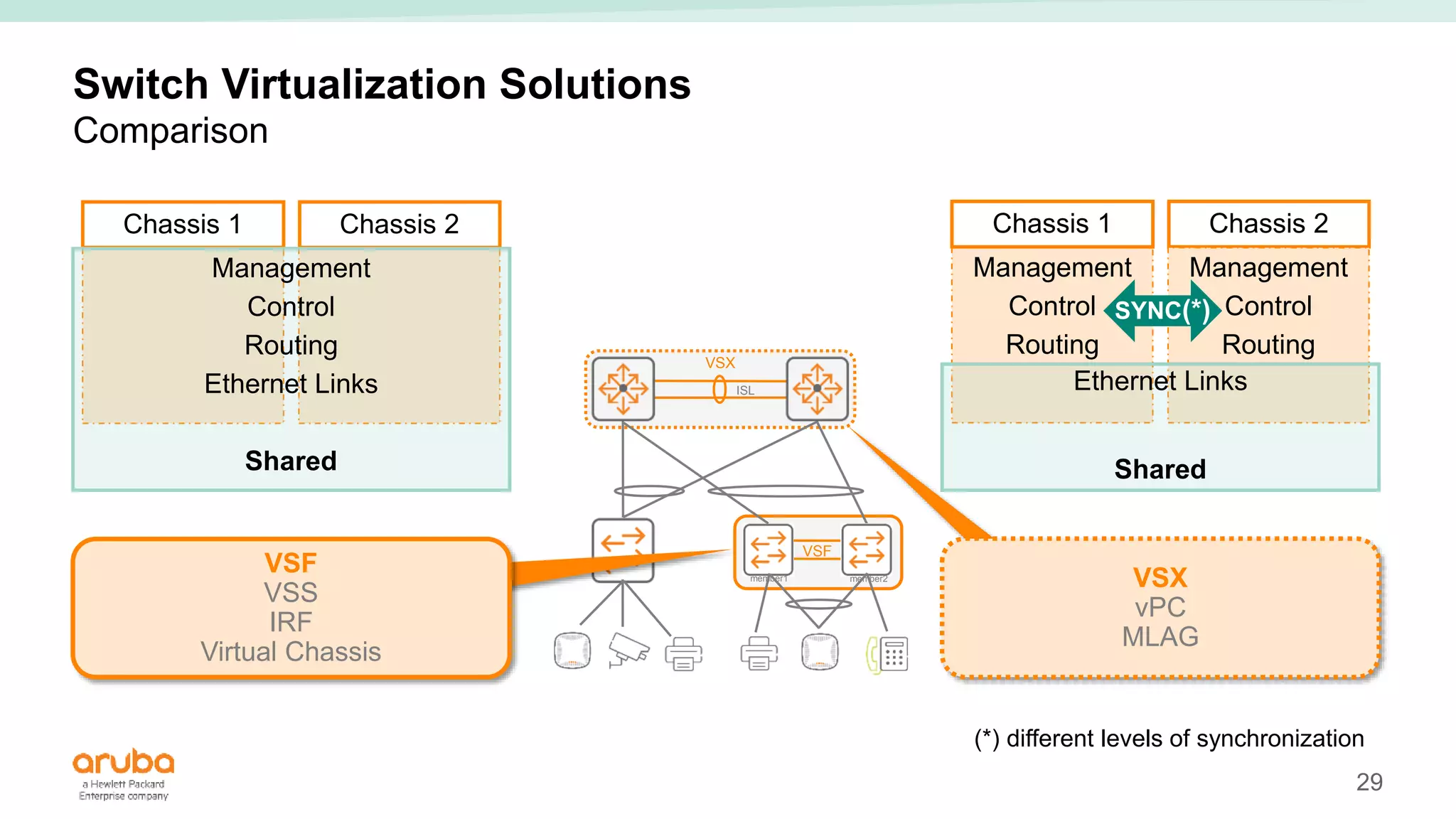
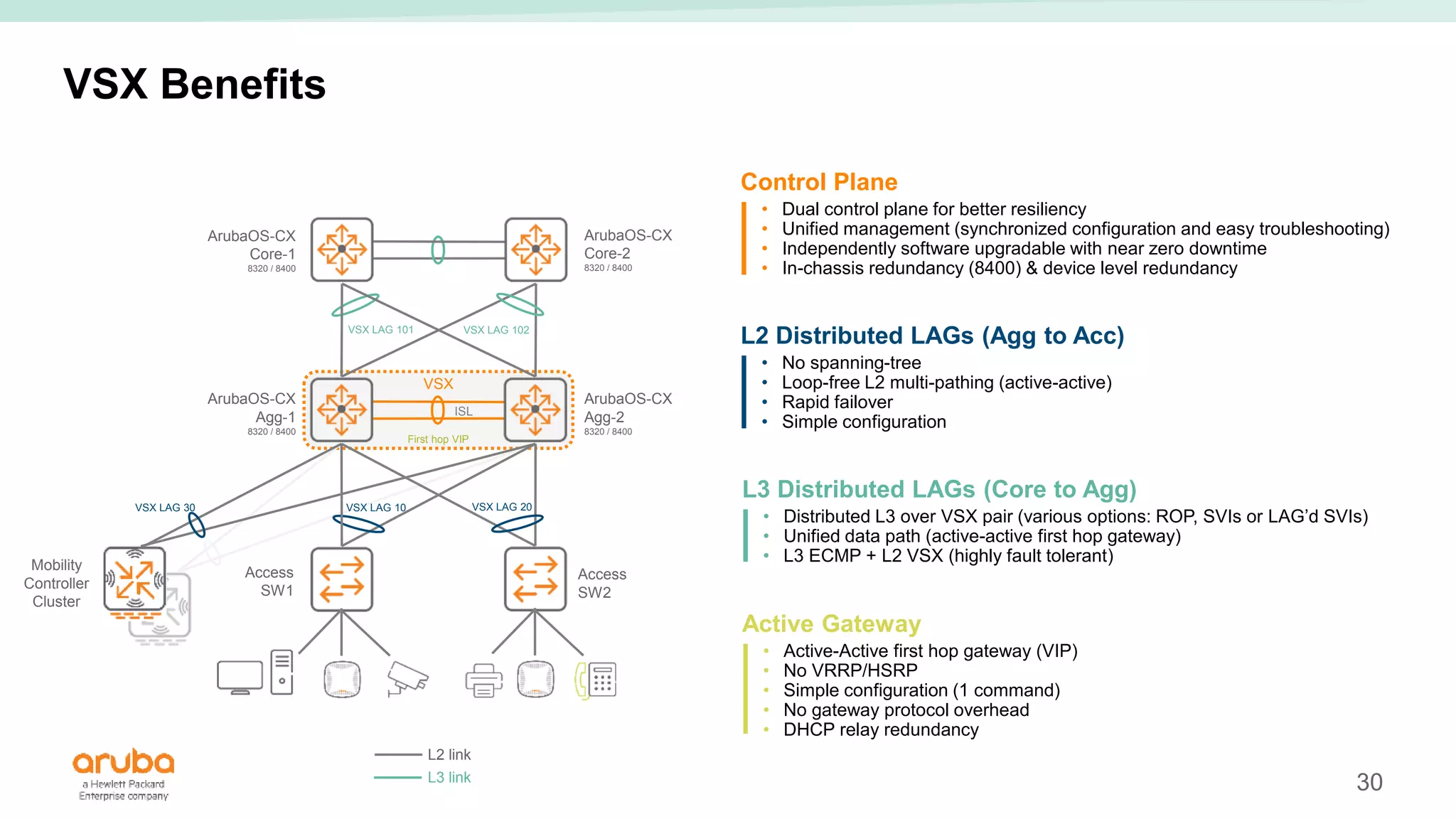
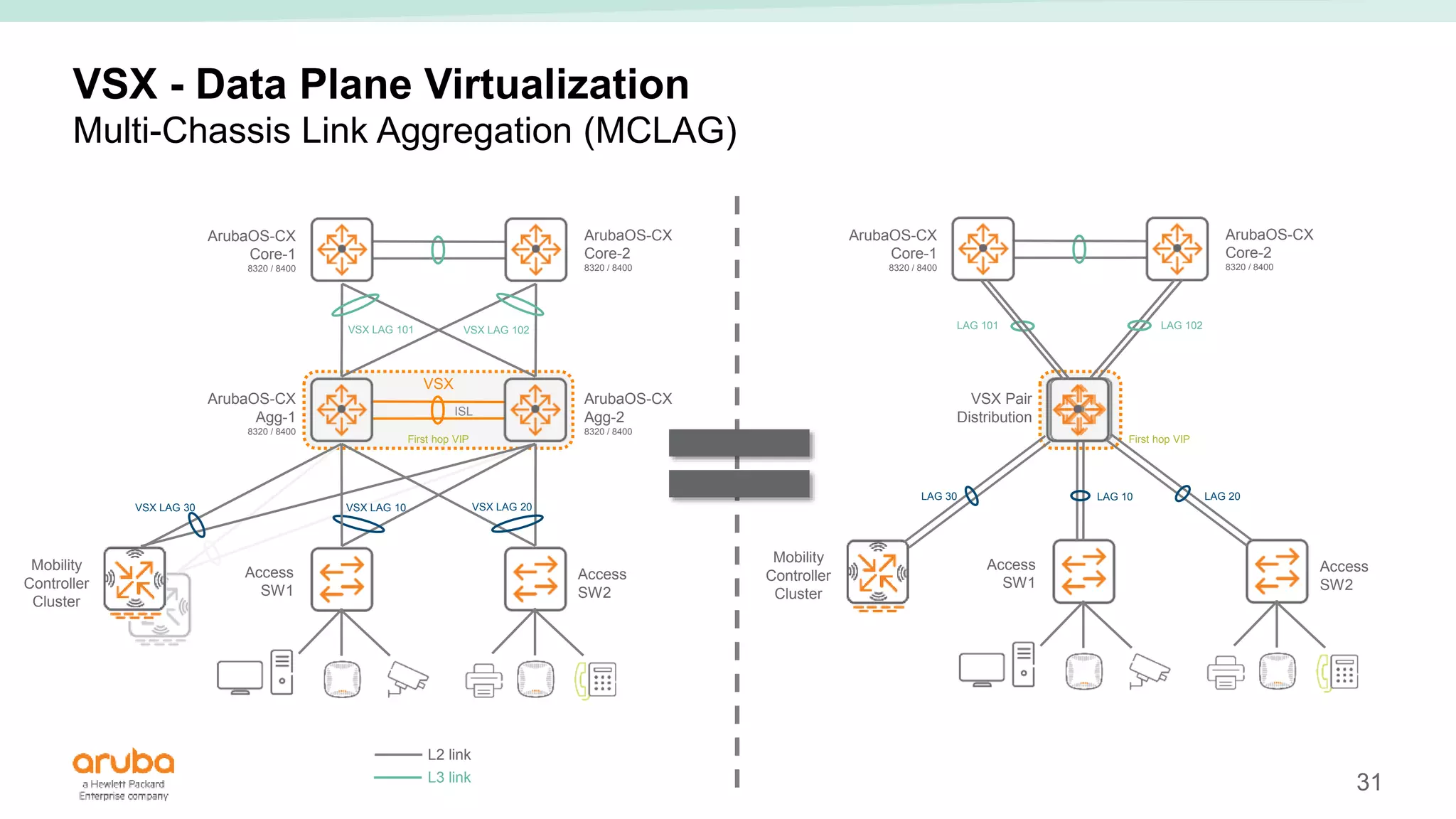
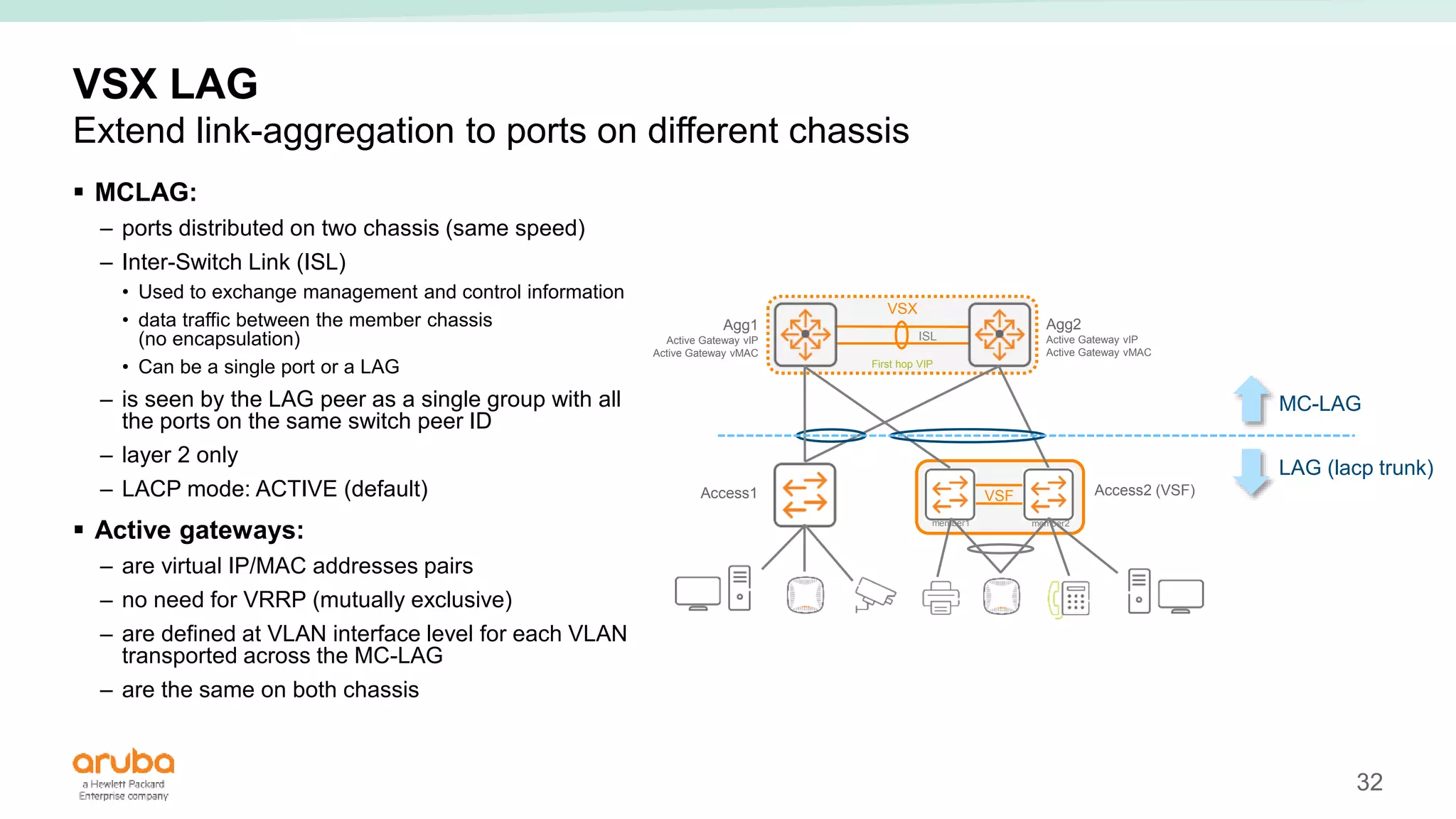
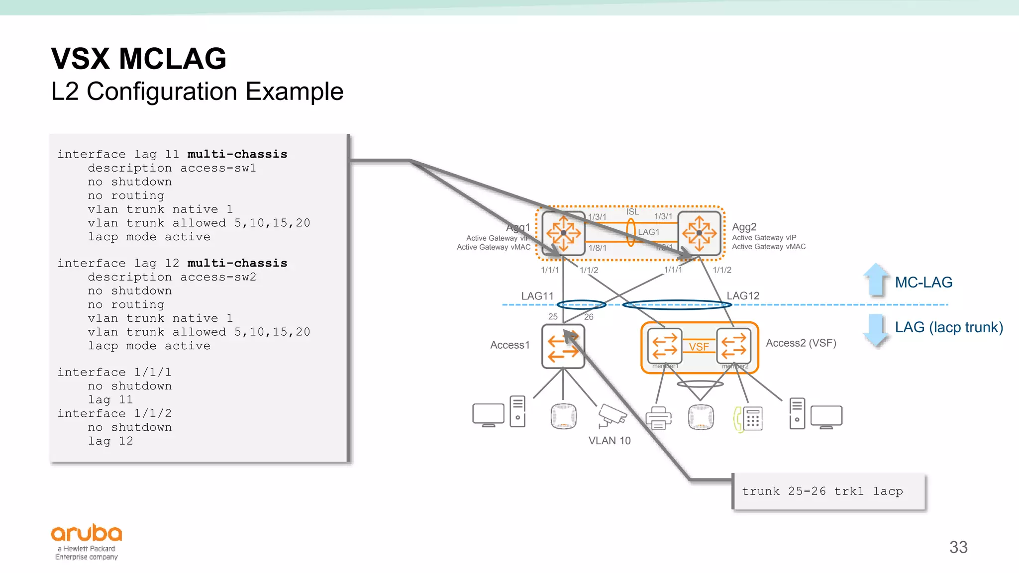
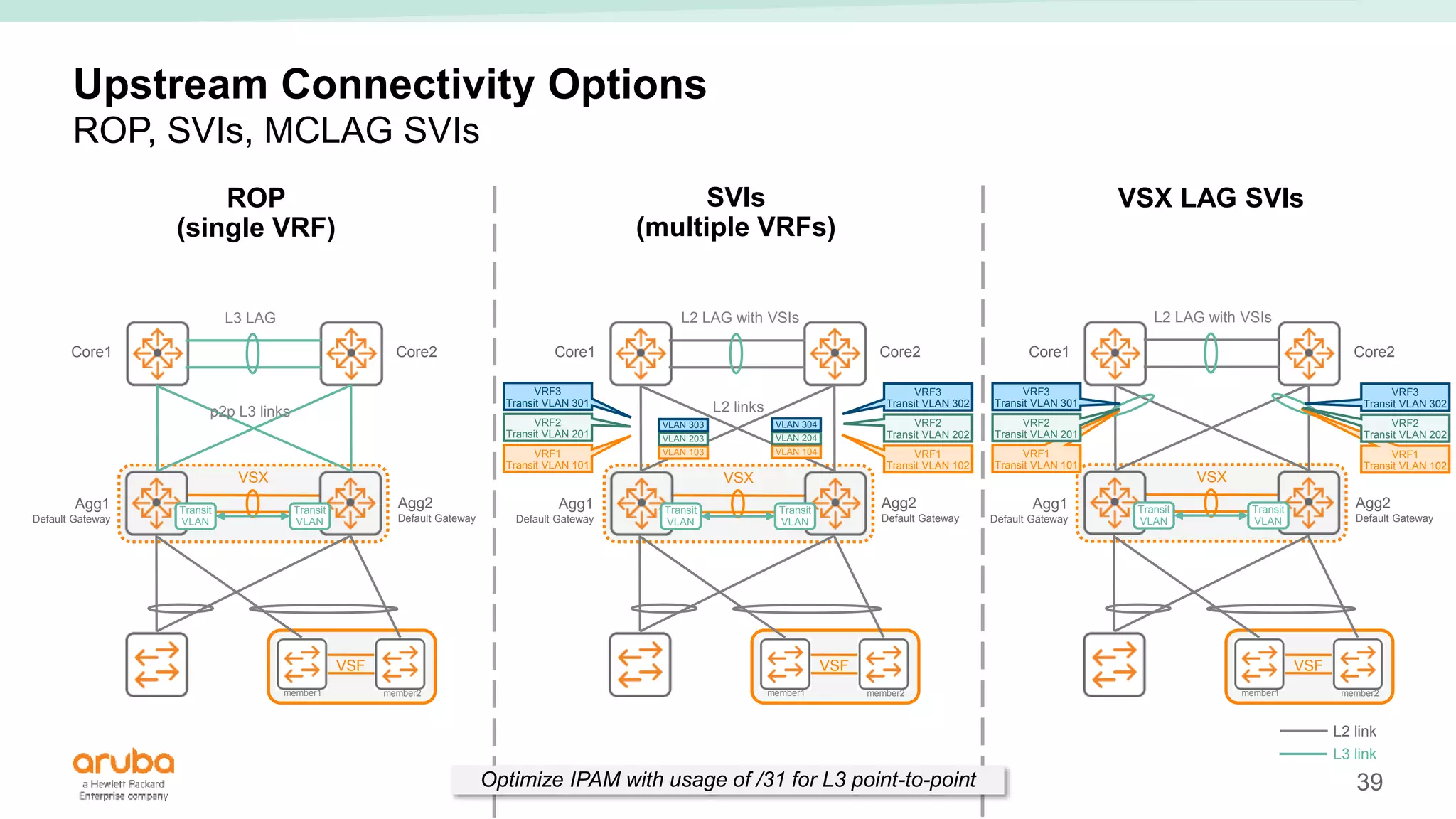
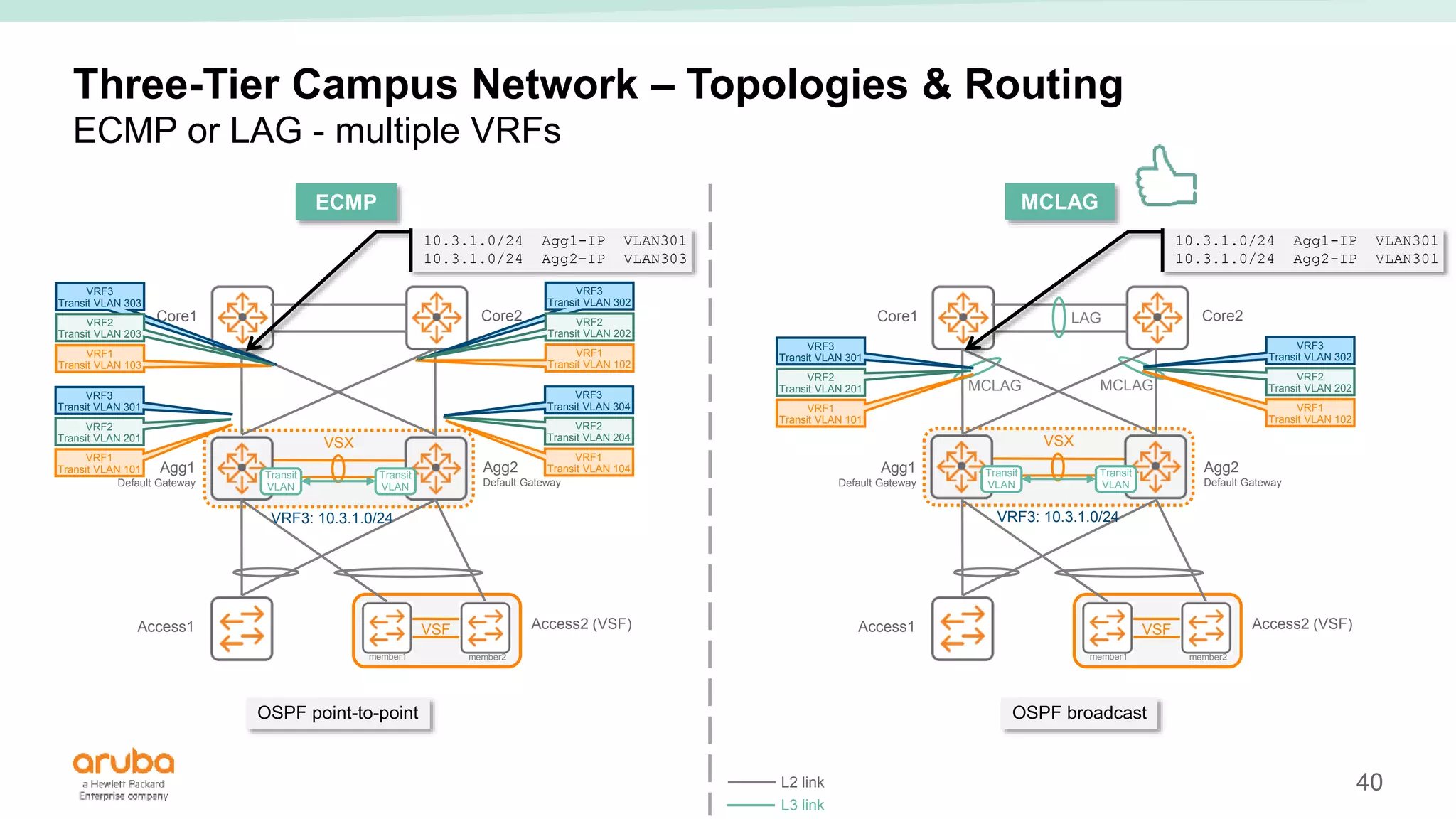
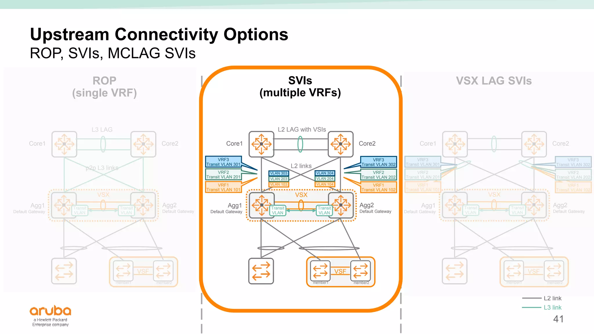
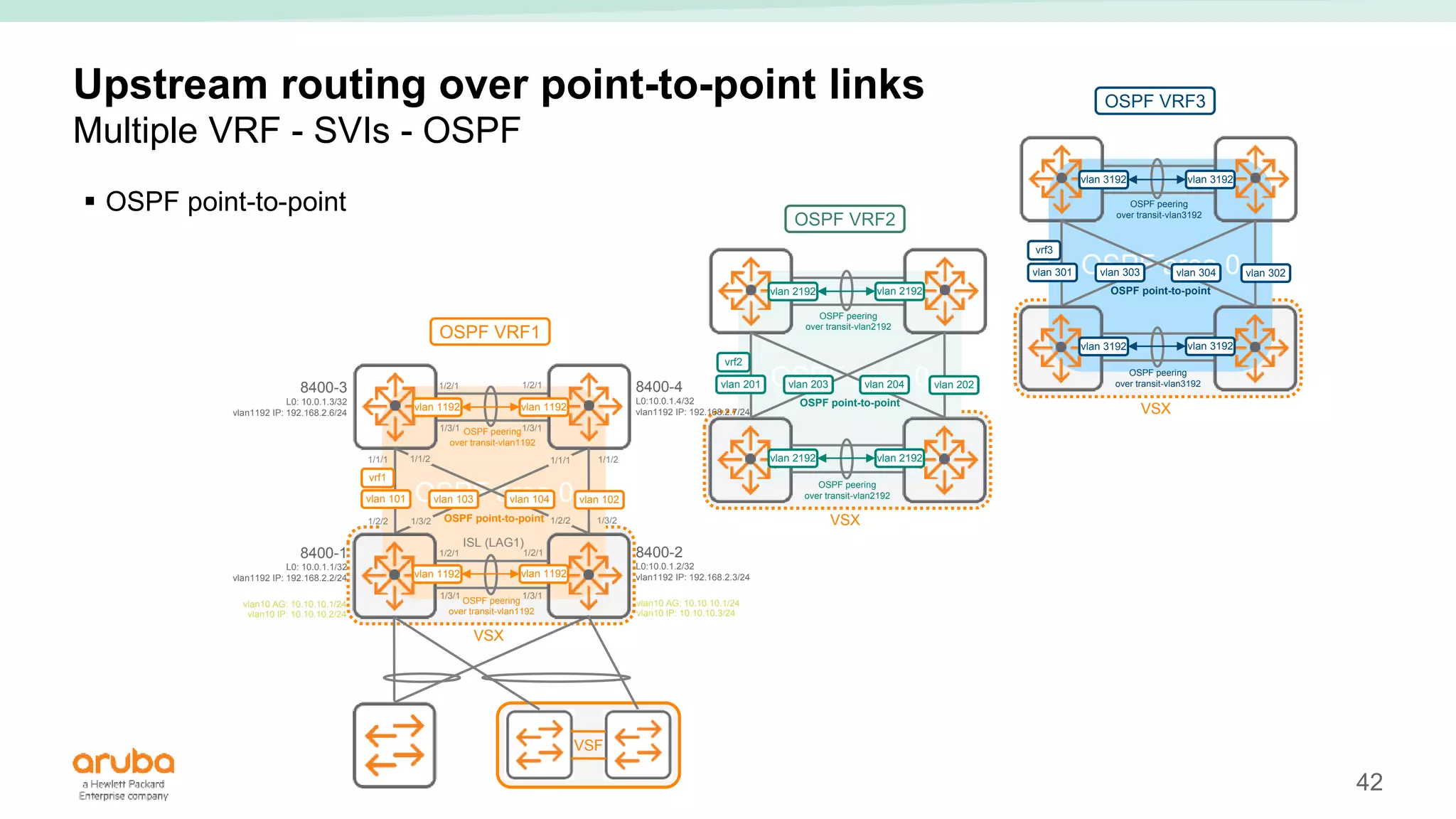
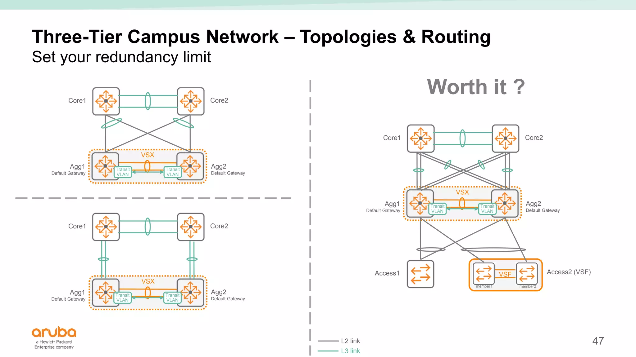
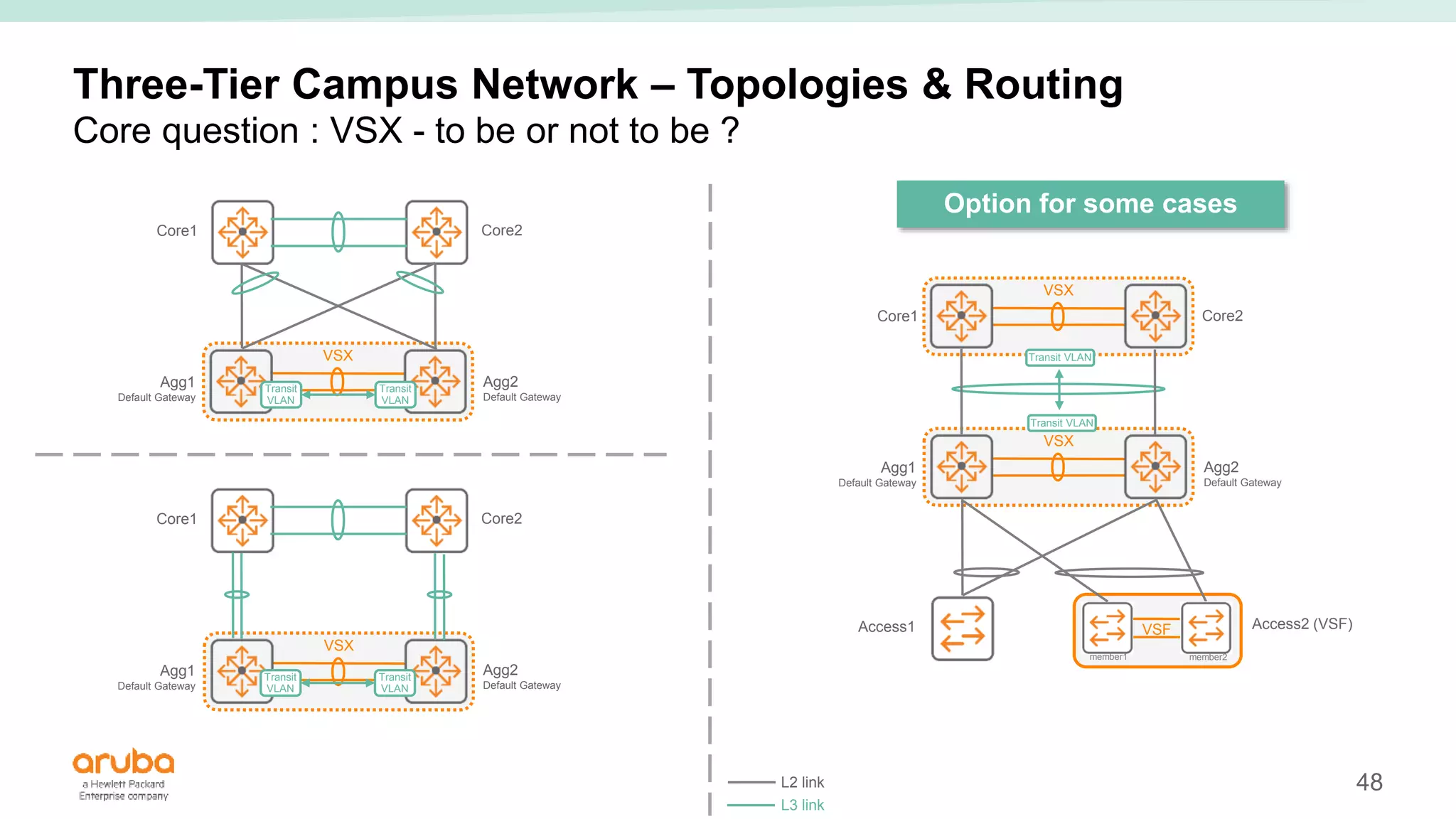
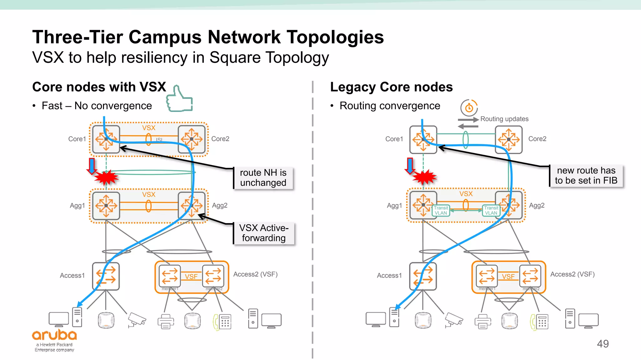
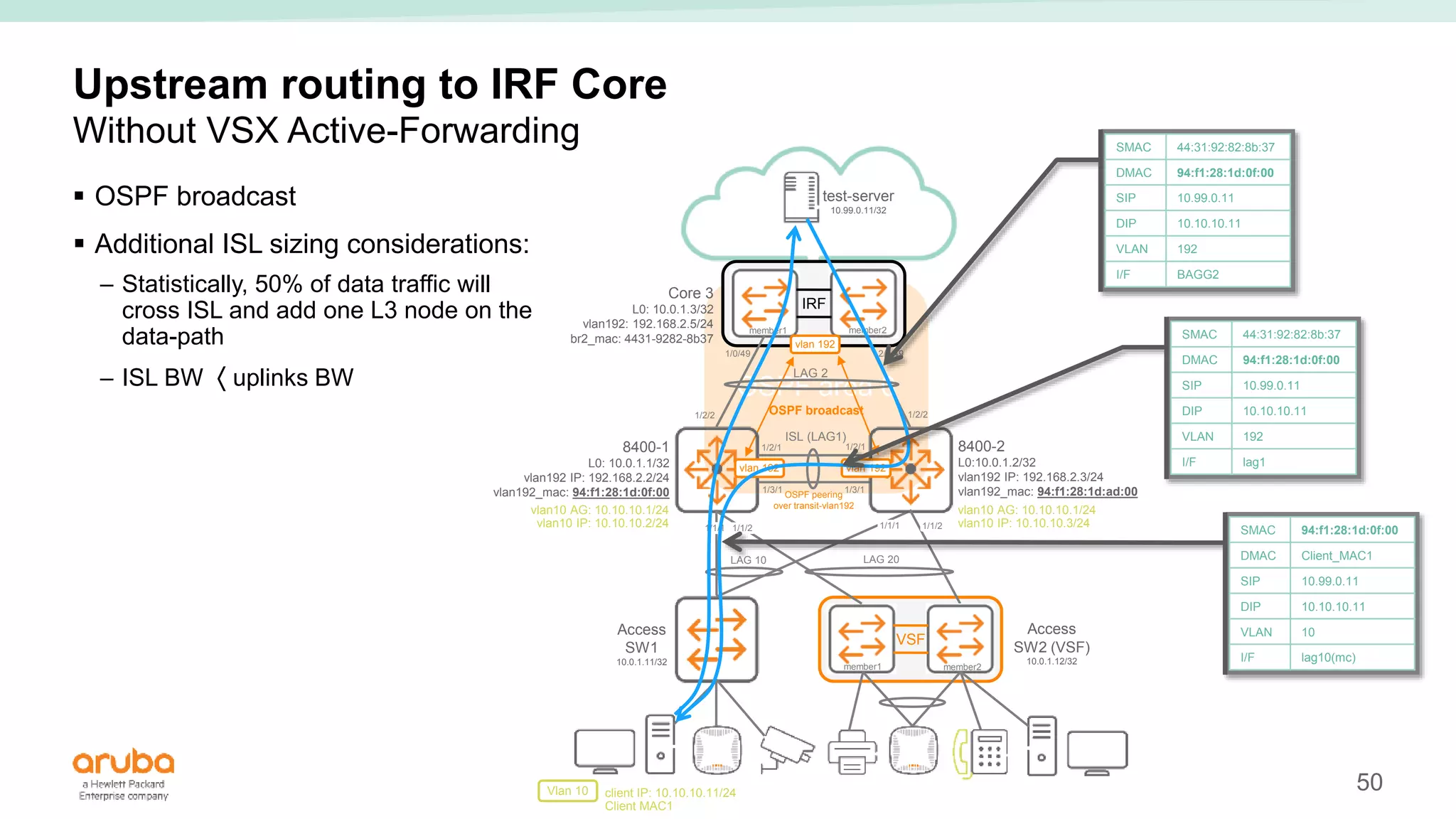
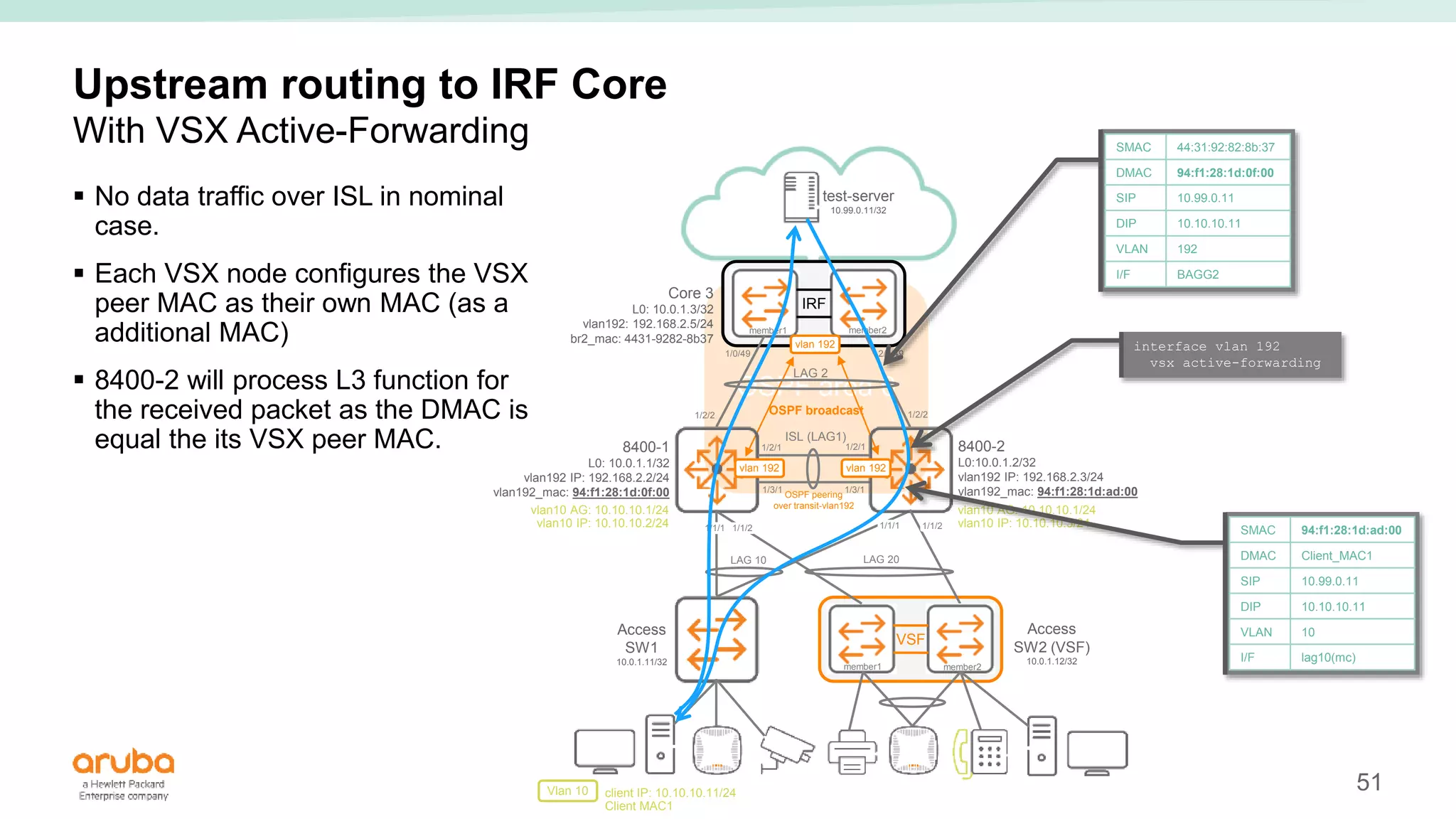
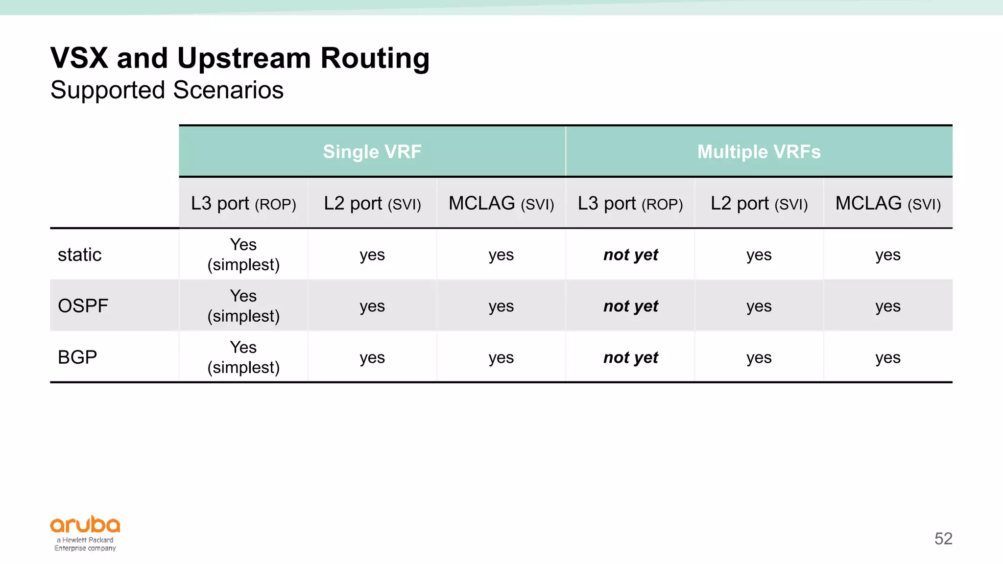
SlideShare a Scribd company logo
1 of 83
Campus Network
Design Best Practices
with ArubaOS-CX
Aruba Campus TME - June 2018
2
Leading Practices
Features &
Function
Performance
Optimization
Leading
Practices
Platform
Evolution
Field
Experience
3
Agenda
Focus Points
1 Campus Architecture
Aruba VSX Technology Overview
2
Loop Protection
4
3 Routing Design & Impact
5 Network Management
6 Miscellaneous
4
Campus Architectures
5
Aruba Mobile-First Solution Components
Wired and wireless
– Core switches : 8400 / 8320
– Aggregation switches : 8320 / 8400 or 3810 / 5400R
– Access switches : 2930F / 2930M / 3810 / 5400R
– Mobility Controllers : 7280 / 7240 / 7220 / 7210 (AppRF, WebCC, UCC, Firewall),
Mobility Master
– Access Points : AP3xx, AP2xx
– Policy Mngt server : ClearPass
– NMS : Airwave (Central)
– 3rd party Firewall and IPS
6
Aruba Mobile-First Design
Impact on core/aggregation design
 Distributed access:
– Wired endpoint traffic bypasses the Mobility Controller
 Centralized access using Dynamic Segmentation (“Role Based / Port Based” Tunneling technologies)
– All wired & wireless traffic goes through Mobility Controllers
– Core and aggregation switches are seen as underlay nodes
 Mix:
– most user traffic going through the Mobility Controller, some exception bypassing the Mobility Controller
(Management traffic, edge/local servers, legacy access switches during migration)
7
Two-Tier Campus Network
Small campus - STP
Access1 Access2 (VSF)
VSF
member1 member2
Mobility
Controller
Cluster
FWs
Core_Agg1
Default Gateway
Core_Agg2
Default Gateway
MC1
MC2
Mobility
Master
L2 link
L3 link
8
ISL
VSX
Two-Tier Campus Network
Small campus - VSX
Access1 Access2 (VSF)
VSF
member1 member2
Mobility
Controller
Cluster
FWs
Core_Agg1
Default Gateway
Core_Agg2
Default Gateway
MC1
MC2
VSX LAG
VSX LAG
Mobility
Master
L2 link
L3 link
9
ISL
VSX
Two-Tier Campus Network
Small campus - VSX
Access1 Access2 (VSF)
VSF
member1 member2
Mobility
Controller
Cluster
FWs
Core_Agg1
Default Gateway
Core_Agg2
Default Gateway
MC1
MC2
VSX LAG
VSX LAG
Mobility
Master
L2 link
L3 link
VSX LAG
10
ISL
VSX
Two-Tier Campus Network
Small campus - VSX
Access1 Access2 (VSF)
VSF
member1 member2
Mobility
Controller
Cluster
FW (Act)
Core_Agg1
Default Gateway
Core_Agg2
Default Gateway
MC1
MC2
MCLAG
MCLAG
Mobility
Master
L2 link
L3 link
FW (Sta)
11
ISL
VSX
Two-Tier Campus Network
Traditional L2/L3 Model
Aruba Switch
Proposal
Access Layer
L2
Mobility
Controller
L2
Aggregation
Layer
L2 + L3
L3 Firewall
8320
2930F/M
Multi
VRFs
Access1 Access2 (VSF)
VSF
member1 member2
Mobility
Controller
Cluster
FWs
MC1
MC2
Mobility
Master
Core_Agg1
Default Gateway
Core_Agg2
Default Gateway
L2 link
L3 link
12
When to split these 2 layers ?
Three-Tier Campus Network
When to have separated Core and Aggregation Layers ?
 Number of access switches >
number of ports in core switch
 Limited number of fibers between
access and core
(IDF required)
 Optics distance limitation between
access and core (MDF)
 Off-loading L2 processes from the
core for large scale
 Fault domains isolation:
– Easier manageability
– Better stability
– Higher scalability:
ARP, MAC, template
Access1 Access2 (VSF)
VSF
member1 member2
Core1 Core2
Agg1 Agg2
MCLAG
MCLAG
L2 link
L3 link
CORE Layer
AGG Layer
agg / core
13
ISL
VSX
Three-Tier Campus Network – medium size
Access1 Access2 (VSF)
VSF
member1 member2
Mobility
Controller
Cluster
Core1 Core2
FWs
Agg1
Default Gateway
Agg2
Default Gateway
MC1
MC2
Mobility
Master
Agg3 Agg4
Traditional Topology Main Floor Second Floor
L2 link
L3 link
VSX
14
Three-Tier Campus Network
L2/L3 or routed access (L3 only) ?
L2 access - L2/L3 aggregation
Pros Cons
Well-known design
model
L2 Loop avoidance
requirements
VSX Benefits
(MCLAG to avoid
Spanning Tree)
LACP requirement
(for VSX LAG)
Large choice of
access switches
L3 access - L3 aggregation
Pros Cons
No L2 protocols,
no Spanning Tree
GRE/VXLAN extra
configuration for VLAN
spanning
Good interoperability Increase IPAM complexity
(try using /31)
Well-known OSPF design
Convergence Time
Not commonly used
by operational teams
Reduced ARP table size Access Platform
restrictions: OSPF and
potentially VRF support
15
Campus Size
Small Campus
Medium Campus
(multiple floors)
Large Campus
(multiple buildings)
L2/L3 Model
2-Tier architecture:
collapsed Core/Aggregation layers.
Distributed or Centralized.
3-Tier architecture:
Separate Core, Aggregation and
Access layers
Distributed or Centralized.
3-Tier architecture:
Separate Core, Aggregation and
Access layers
Distributed or Centralized.
Inter-Core routing
L3 only Model
(routed access)
Not attractive.
Centralized.
(Distributed if single VRF.)
Centralized.
(Distributed if single VRF.)
Inter-Core routing
16
VSX
VSX
VSX
Three-Tier Campus Network
Mobility Controller attachment
To Core
• Core must perform L2 and L3
To dedicated aggregation switches
• Recommended for large number of dual-stack (v4+v6) clients
• Off-load L2/L3 processing from Core
• Fault Domain isolation between wireless and core
Core1
Wireless
Default GW
Core2
Wireless
Default GW
Mobility
Controller
Cluster
MC1
Agg1 Agg2
Core1 Core2
MC1
Agg1 Agg2
MC2 Agg3
Wireless
Default GW
Agg4
Wireless
Default GW
MC2
L2 link
L3 link
17
ISL
VSX
Aruba Switch
Proposal
Three-Tier Campus Network
Traditional L2+L3
Access1 Access2 (VSF)
VSF
member1 member2
Mobility
Controller
Cluster
Core1 Core2
FWs
MC1
MC2
Access Layer
L2
Mobility
Controller
L2
Aggregation
Layer
L2 + L3
Core Layer
L3
L3 Firewall
8400
8320
8400
8320
2930F/M
Multi
VRFs
Multi
VRFs
Mobility
Master
Agg1
Default Gateway
Agg2
Default Gateway
L2 link
L3 link
18
ISL
VSX
Aruba Switch
Proposal
Core Layer
L2+L3
L2 Firewall
Access Layer
L2
Mobility
Controller
L2
Aggregation
Layer
L2 only
Three-Tier Campus Network
In few cases: L2+L3 with L2 FW/IPS
Access1 Access2 (VSF)
VSF
member1 member2
Mobility
Controller
Cluster
FW1 FW2
Agg1 Agg2
MC1
MC2
Core1
Default Gateway
Core2
Default Gateway
8400
8320
8400
8320
2930F/M
3810
No VRF
dependency
5400R
Multi
VRFs
Mobility
Master
L3 FWs
No VRF
dependency
L2 link
L3 link
19
ISL
VSX
ISL
VSX
Aruba Switch
Proposal
Access Layer
L2
Mobility
Controller
L2
Aggregation
Layer
L2 only
Three-Tier Campus Network
In few cases: L2+L3 with L2 FW/IPS
Access1 Access2 (VSF)
VSF
member1 member2
Agg1 Agg2
8400
8320
8400
8320
2930F/M
3810
No VRF
dependency
5400R
Mobility
Master
Agg3 Agg4
Core Layer
L2+L3
L2 Firewall
FW1 FW2
Core1
Default Gateway
Core2
Default Gateway
Multi
VRFs
L3 FWs
GRE
No VRF
dependency
L2 link
L3 link
20
ISL
VSX
L3 Firewall
Aruba Switch
Proposal
Access Layer
L2
Mobility
Controller
L2
Aggregation
Layer
L2 only
Three-Tier Campus Network
10% of cases: L2+L3 with L3 FW
Access1 Access2 (VSF)
VSF
member1 member2
Mobility
Controller
Cluster
Agg1 Agg2
MC1
MC2
8400
8320
2930F/M
3810
5400R
No VRF
dependency
Multi
VRFs
Mobility
Master
FW1
Default Gateway
FW2
Default Gateway
L2 link
L3 link
21
ISL
VSX
Aruba Switch
Proposal
Three-Tier Campus Network
L3 Access Model for Centralized Access
Access1 Access2 (VSF)
VSF
member1 member2
Mobility
Controller
Cluster
Core1 Core2
FWs
Agg1 Agg2
MC1
MC2
Access Layer
L3
Mobility
Controller
L2
Aggregation
Layer
L3
Core Layer
L3
L3 Firewall
8400
8320
8400
8320
2930F/M
Multi
VRFs
Multi
VRFs
Mobility
Master
No VRF dependency
with Dynamic
Segmentation
L2 link
L3 link
22
VSX VSX VSX
VSX
Three-Tier Campus Network
Large Campus with dark fibers
Building 1 - Main Floor
Building 1 – Second Floor
Core1
Wireless
Default GW
Core2
Wireless
Default GW
Mobility
Controller
Cluster
MC1
Agg1 Agg2
MC2
Building 2 – Main Floor
Core3
Agg5 Agg6
Core4
Agg3 Agg4 Agg7 Agg8
Building 2 – Second Floor
23
VSX VSX VSX
VSX
Three-Tier Campus Network
Large Campus with reduced number of fibers (square routing)
Building 1 - Main Floor
Building 1 – Second Floor
Core1
Wireless
Default GW
Core2
Wireless
Default GW
Mobility
Controller
Cluster
MC1
Agg1 Agg2
MC2
Building 2 – Main Floor
Core3
Agg5 Agg6
Core4
Agg3 Agg4 Agg7 Agg8
Building 2 – Second Floor
24
VSX VSX VSX
VSX
Three-Tier Campus Network
Large Campus with dark fibers and L2 extension
Building 1 - Main Floor
Building 1 – Second Floor
Core1
Wireless
Default GW
Core2
Wireless
Default GW
Mobility
Controller
Cluster
MC1
Agg1 Agg2
MC2
Building 2 – Main Floor
Core3
Agg5 Agg6
Core4
Agg3 Agg4 Agg7 Agg8
Building 2 – Second Floor
MC3
MC4
25
VSX VSX VSX
VSX
Large Campus Network
No inter-building L2 extension: use mobile-first design with Dynamic Segmentation
Building 1 - Main Floor
Building 1 – Second Floor
L2 link
L3 link
Core1
Wireless
Default GW
Core2
Wireless
Default GW
Mobility
Controller
Cluster
MC1
Agg1 Agg2
MC2
Building 2 – Main Floor
Core3
Agg5 Agg6
Core4
Agg3 Agg4 Agg7 Agg8
Building 2 – Second Floor
Provider Managed
26
Distribution Switch Selection
Sizing Considerations
• The current max scaling is 100,000 clients per Mobility Controllers Cluster.
• Larger deployments require multiple clusters each with their own distribution layer switches.
• Switch capacity drives the number of supported clients per Mobility Controller Clusters module.
Switch Series
ARP
Max. IPv4 Addresses
ND
Max. IPv6 Addresses
ARP/ND
Max. IPv4+IPv6 Addresses
(dual-stack)
1 IPv4
1 IPv6 Link-Local
1 IPv6 SLAAC or DHCPv6
Aruba 3810 Series 25 000 12 500 8 300 5 000
Aruba 5400R Series 25 000 12 500 8 300 5 000
Aruba 8320 Series 125 000 57 344 38 200 23 000
Aruba 8400 Series 131 072 65 536 65 536 32 768
27
Aruba Virtual Switching Extension (VSX)
Overview
28
Aruba Virtual Switching Extension
VSX Principles
 High Availability by design during upgrades
 Support for active-active data-path:
• Active-active L2
• Active-active L3 unicast
• Active-active L3 multicast*
 Operational simplicity and usability:
• for configuration
• for troubleshooting
 Similar VSF benefits with better HA during upgrade
ISL
VSX
* This requires future ArubaOS-CX release
29
VSX
vPC
MLAG
Switch Virtualization Solutions
Comparison
Chassis 1 Chassis 2
Management
Control
Routing
Chassis 1 Chassis 2
Management
Control
Routing
Ethernet Links
Shared
Management
Control
Routing
Ethernet Links
Shared
SYNC?
SYNC(*)
(*) different levels of synchronization
ISL
VSF
member1 member2
VSF
VSS
IRF
Virtual Chassis
VSX
30
ISL
VSX
First hop VIP
VSX Benefits
Mobility
Controller
Cluster
L2 link
L3 link
Access
SW1
ArubaOS-CX
Agg-1
8320 / 8400
Access
SW2
ArubaOS-CX
Core-1
8320 / 8400
ArubaOS-CX
Core-2
8320 / 8400
• Dual control plane for better resiliency
• Unified management (synchronized configuration and easy troubleshooting)
• Independently software upgradable with near zero downtime
• In-chassis redundancy (8400) & device level redundancy
Control Plane
• No spanning-tree
• Loop-free L2 multi-pathing (active-active)
• Rapid failover
• Simple configuration
L2 Distributed LAGs (Agg to Acc)
• Distributed L3 over VSX pair (various options: ROP, SVIs or LAG’d SVIs)
• Unified data path (active-active first hop gateway)
• L3 ECMP + L2 VSX (highly fault tolerant)
L3 Distributed LAGs (Core to Agg)
• Active-Active first hop gateway (VIP)
• No VRRP/HSRP
• Simple configuration (1 command)
• No gateway protocol overhead
• DHCP relay redundancy
Active Gateway
VSX LAG 20
VSX LAG 10
VSX LAG 30
VSX LAG 101
ArubaOS-CX
Agg-2
8320 / 8400
VSX LAG 102
31
ISL
VSX
First hop VIP
VSX - Data Plane Virtualization
Multi-Chassis Link Aggregation (MCLAG)
VSX LAG 20
Mobility
Controller
Cluster
Access
SW1
ArubaOS-CX
Agg-1
8320 / 8400
ArubaOS-CX
Agg-2
8320 / 8400
Access
SW2
ArubaOS-CX
Core-1
8320 / 8400
ArubaOS-CX
Core-2
8320 / 8400
VSX LAG 10
VSX LAG 30
VSX Pair
Distribution
LAG 20
Mobility
Controller
Cluster
Access
SW1
Access
SW2
LAG 30
First hop VIP
LAG 101
LAG 10
VSX LAG 101 VSX LAG 102
ArubaOS-CX
Core-1
8320 / 8400
ArubaOS-CX
Core-2
8320 / 8400
LAG 102
L2 link
L3 link
32
ISL
VSX
First hop VIP
VSX LAG
Extend link-aggregation to ports on different chassis
 MCLAG:
– ports distributed on two chassis (same speed)
– Inter-Switch Link (ISL)
• Used to exchange management and control information
• data traffic between the member chassis
(no encapsulation)
• Can be a single port or a LAG
– is seen by the LAG peer as a single group with all
the ports on the same switch peer ID
– layer 2 only
– LACP mode: ACTIVE (default)
 Active gateways:
– are virtual IP/MAC addresses pairs
– no need for VRRP (mutually exclusive)
– are defined at VLAN interface level for each VLAN
transported across the MC-LAG
– are the same on both chassis
Access1 Access2 (VSF)
VSF
member1 member2
Agg1
Active Gateway vIP
Active Gateway vMAC
Agg2
Active Gateway vIP
Active Gateway vMAC
MC-LAG
LAG (lacp trunk)
33
VSX MCLAG
L2 Configuration Example
Access1
ISL
Access2 (VSF)
VSF
member1 member2
MC-LAG
LAG (lacp trunk)
LAG1
LAG11 LAG12
VLAN 10
1/1/1 1/1/2 1/1/1 1/1/2
Agg1
Active Gateway vIP
Active Gateway vMAC
Agg2
Active Gateway vIP
Active Gateway vMAC
1/3/1
1/8/1
1/3/1
1/8/1
trunk 25-26 trk1 lacp
25 26
interface lag 11 multi-chassis
description access-sw1
no shutdown
no routing
vlan trunk native 1
vlan trunk allowed 5,10,15,20
lacp mode active
interface lag 12 multi-chassis
description access-sw2
no shutdown
no routing
vlan trunk native 1
vlan trunk allowed 5,10,15,20
lacp mode active
interface 1/1/1
no shutdown
lag 11
interface 1/1/2
no shutdown
lag 12
34
VSX MCLAG
L3 Active/Active Configuration Example
Access1
ISL
Access2 (VSF)
VSF
member1 member2
MCLAG
LAG (lacp trunk)
LAG1
LAG11 LAG12
VLAN 10
1/1/1 1/1/2 1/1/1 1/1/2
Agg1
Active Gateway vIP
Active Gateway vMAC
Agg2
Active Gateway vIP
Active Gateway vMAC
1/3/1
1/8/1
1/3/1
1/8/1
25 26
vrf vrf1
interface vlan10
vrf attach vrf1
ip address 10.10.10.3/26
active-gateway ip 10.10.10.1 00:00:00:00:10:01
vrf vrf1
interface vlan10
vrf attach vrf1
ip address 10.10.10.2/26
active-gateway ip 10.10.10.1 00:00:00:00:10:01
35
Routing Design & Architecture Impact
Using VSX
36
VSX LAG and upstream routing
Constraints Diversity
 L2 or L3 links with upstream core nodes ?
 Static ? OSPF ? BGP ?
 Single VRF / Multiple VRF
 Sizing / limitations
 Best practice for HA
VSX
Access1 Access2 (VSF)
VSF
member1 member2
Core1 Core2
Agg1
Default Gateway
Agg2
Default Gateway
Transit
VLAN
Transit
VLAN
LAG
MCLAG MCLAG
?
?
?
?
L2 link
L3 link
 In all scenarios, the 2 VSX switches run independent control planes (OSPF/BGP) and present
themselves as different routers with their own Router_IDs in the network.
 In the data path however, they function as a single router and support active-active forwarding.
37
Definition
SVI / ROP
SVI:
– A Switched Virtual Interface (SVI) is a logical Layer 3 interface configured per VLAN (one-
to-one mapping) that perform all Layer 3 processing for packets to or from all switch ports
associated with that VLAN.
ROP:
– A Routed Only Port is a physical port on a switch that process all Layer 3 functions for
packets to or form the said port without any binding to VLAN processing.
38
L3 Link Aggregation
Features / Practices
– L3 LAG are supported
– Configuration developed/tested using L3.
– 128 LAG interfaces Max
– Can use up to 8 interfaces per LAG
– Optimal design uses LAGs between L3 blocks
(see reference topology)
CLI
Configure the LAG interface
interface lag <LAG-ID>
description LAG to Core Switch 1
no shutdown
lacp mode active
ip address <IP-ADDR>/<Prefix-Len>
Associate member links with the LAG interface
interface <IFACE-ID>
description LAG to Core Switch 1
no shutdown
lag <LAG-ID>
39
VSX
Transit
VLAN
Transit
VLAN
VSX
Transit
VLAN
Transit
VLAN
VSX
Transit
VLAN
Transit
VLAN
Upstream Connectivity Options
ROP, SVIs, MCLAG SVIs
VSF
member1 member2
Core1 Core2
Agg1
Default Gateway
Agg2
Default Gateway
VSF
member1 member2
Core1 Core2
Agg1
Default Gateway
Agg2
Default Gateway
VSF
member1 member2
Core1 Core2
Agg1
Default Gateway
Agg2
Default Gateway
ROP
(single VRF)
VSX LAG SVIs
SVIs
(multiple VRFs)
Optimize IPAM with usage of /31 for L3 point-to-point
L2 link
L3 link
p2p L3 links
L3 LAG
L2 links
L2 LAG with VSIs
VRF1
Transit VLAN 101
VRF2
Transit VLAN 201
VRF3
Transit VLAN 301
VRF1
Transit VLAN 102
VRF2
Transit VLAN 202
VRF3
Transit VLAN 302
VLAN 103
VLAN 203
VLAN 303
VLAN 104
VLAN 204
VLAN 304
VRF1
Transit VLAN 101
VRF2
Transit VLAN 201
VRF3
Transit VLAN 301
VRF1
Transit VLAN 102
VRF2
Transit VLAN 202
VRF3
Transit VLAN 302
L2 LAG with VSIs
40
VSX
VSX
Three-Tier Campus Network – Topologies & Routing
Access1 Access2 (VSF)
VSF
member1 member2
Core1 Core2
Agg2
Default Gateway
ECMP or LAG - multiple VRFs
Access1 Access2 (VSF)
VSF
member1 member2
Core1 Core2
Agg1
Default Gateway
Agg2
Default Gateway
ECMP MCLAG
Transit
VLAN
Transit
VLAN
Transit
VLAN
Transit
VLAN
LAG
MCLAG MCLAG
VRF1
Transit VLAN 101
VRF2
Transit VLAN 201
VRF3
Transit VLAN 301
Agg1
Default Gateway
VRF1
Transit VLAN 103
VRF3
Transit VLAN 303
VRF2
Transit VLAN 203
VRF1
Transit VLAN 104
VRF2
Transit VLAN 204
VRF3
Transit VLAN 304
VRF1
Transit VLAN 102
VRF3
Transit VLAN 302
VRF2
Transit VLAN 202
VRF1
Transit VLAN 101
VRF2
Transit VLAN 201
VRF3
Transit VLAN 301
VRF1
Transit VLAN 102
VRF2
Transit VLAN 202
VRF3
Transit VLAN 302
VRF3: 10.3.1.0/24
10.3.1.0/24 Agg1-IP VLAN301
10.3.1.0/24 Agg2-IP VLAN303
10.3.1.0/24 Agg1-IP VLAN301
10.3.1.0/24 Agg2-IP VLAN301
VRF3: 10.3.1.0/24
L2 link
L3 link
OSPF point-to-point OSPF broadcast
41
VSX
Transit
VLAN
Transit
VLAN
VSX
Transit
VLAN
Transit
VLAN
VSX
Transit
VLAN
Transit
VLAN
Upstream Connectivity Options
ROP, SVIs, MCLAG SVIs
VSF
member1 member2
Core1 Core2
Agg1
Default Gateway
Agg2
Default Gateway
VSF
member1 member2
Core1 Core2
Agg1
Default Gateway
Agg2
Default Gateway
VSF
member1 member2
Core1 Core2
Agg1
Default Gateway
Agg2
Default Gateway
ROP
(single VRF)
VSX LAG SVIs
SVIs
(multiple VRFs)
L2 link
L3 link
p2p L3 links
L3 LAG
L2 links
L2 LAG with VSIs
VRF1
Transit VLAN 101
VRF2
Transit VLAN 201
VRF3
Transit VLAN 301
VRF1
Transit VLAN 102
VRF2
Transit VLAN 202
VRF3
Transit VLAN 302
VLAN 103
VLAN 203
VLAN 303
VLAN 104
VLAN 204
VLAN 304
VRF1
Transit VLAN 101
VRF2
Transit VLAN 201
VRF3
Transit VLAN 301
VRF1
Transit VLAN 102
VRF2
Transit VLAN 202
VRF3
Transit VLAN 302
42
OSPF area 0
VSX
OSPF area 0
VSX
OSPF area 0
Upstream routing over point-to-point links
Multiple VRF - SVIs - OSPF
VSF
1/2/1
1/3/1
1/2/1
1/3/1
1/2/2 1/2/2
1/3/2 1/3/2
1/1/1
1/2/1
1/3/1
1/2/1
1/3/1
1/1/1
1/1/2 1/1/2
vlan10 AG: 10.10.10.1/24
vlan10 IP: 10.10.10.2/24
vlan10 AG: 10.10.10.1/24
vlan10 IP: 10.10.10.3/24
ISL (LAG1)
vlan 1192 vlan 1192
OSPF peering
over transit-vlan1192
vlan 1192 vlan 1192
OSPF peering
over transit-vlan1192
OSPF point-to-point
8400-3
L0: 10.0.1.3/32
vlan1192 IP: 192.168.2.6/24
8400-4
L0:10.0.1.4/32
vlan1192 IP: 192.168.2.7/24
8400-1
L0: 10.0.1.1/32
vlan1192 IP: 192.168.2.2/24
8400-2
L0:10.0.1.2/32
vlan1192 IP: 192.168.2.3/24
vrf1
vlan 2192 vlan 2192
OSPF peering
over transit-vlan2192
vlan 2192 vlan 2192
OSPF peering
over transit-vlan2192
OSPF point-to-point
vrf2
vlan 3192 vlan 3192
OSPF peering
over transit-vlan3192
vlan 3192 vlan 3192
OSPF peering
over transit-vlan3192
OSPF point-to-point
vrf3
vlan 101 vlan 103 vlan 104 vlan 102
vlan 201 vlan 203 vlan 204 vlan 202
vlan 301 vlan 303 vlan 304 vlan 302
OSPF VRF1
OSPF VRF2
OSPF VRF3
 OSPF point-to-point
VSX
43
VSX
Transit
VLAN
Three-Tier Campus Network – Topologies & Routing
Triangles converge faster than square
ECMP + Triangles
• Fast - No convergence needed
Square
• Routing convergence
Access1 Access2 (VSF)
VSF
member1 member2
Core1 Core2
Agg1 Agg2
Access1 Access2 (VSF)
VSF
member1 member2
Core1 Core2
Agg1 Agg2
Routing updates
VSX
Transit
VLAN
Transit
VLAN
Transit
VLAN
route already
in FIB
new route has
to be set in FIB
L2 link
L3 link
44
VSX
VSX
Three-Tier Campus Network – Topologies & Routing
Access1 Access2 (VSF)
VSF
member1 member2
Core1 Core2
Agg1
Default Gateway
Agg2
Default Gateway
MC-LAG
MC-LAG
ECMP or LAG - single VRF
Access1 Access2 (VSF)
VSF
member1 member2
Core1 Core2
Agg1
Default Gateway
Agg2
Default Gateway
ECMP MCLAG
8400-2# show ip ecmp
ECMP Configuration
---------------------
ECMP Status : Enabled
ECMP Load Balancing by
------------------------
Source IP : Enabled
Destination IP : Enabled
Source Port : Enabled
Destination Port : Enabled
8400-1(config-ospf-1)# maximum-paths
<1-8> Number of ECMP routes. Default is 4.
8400-1(config)# lacp hash
l2-src-dst Base the hash on l2-src-dst
l3-src-dst Base the hash on l3-src-dst
l4-src-dst Base the hash on l4-src-dst
Transit
VLAN
Transit
VLAN
Transit
VLAN
Transit
VLAN
LAG
MCLAG MCLAG
L2 link
L3 link
45
VSX
VSX
Three-Tier Campus Network – Topologies & Routing
Access1 Access2 (VSF)
VSF
member1 member2
Core1 Core2
Agg1
Default Gateway
Agg2
Default Gateway
More redundancy with recommended additional links - square
Access1 Access2 (VSF)
VSF
member1 member2
Core1 Core2
Agg1
Default Gateway
Agg2
Default Gateway
Transit
VLAN
Transit
VLAN
Transit
VLAN
Transit
VLAN
Link failure protection would
require area 0 on Agg layer
Port from
Line Card A
Port from
Line Card B
L2 link
L3 link
46
VSX
VSX
Three-Tier Campus Network – Topologies & Routing
Access1 Access2 (VSF)
VSF
member1 member2
Core1 Core2
Agg1
Default Gateway
Agg2
Default Gateway
More redundancy with recommended additional links - triangles
Access1 Access2 (VSF)
VSF
member1 member2
Core1 Core2
Agg1
Default Gateway
Agg2
Default Gateway
Transit
VLAN
Transit
VLAN
Transit
VLAN
Transit
VLAN
Link failure protection would
require area 0 on Agg layer
Port from
Line Card A
Port from
Line Card B
L2 link
L3 link
47
VSX
Three-Tier Campus Network – Topologies & Routing
Set your redundancy limit
Access1 Access2 (VSF)
VSF
member1 member2
Core1 Core2
Agg1
Default Gateway
Agg2
Default Gateway
Worth it ?
VSX
Core1 Core2
Agg1
Default Gateway
Agg2
Default Gateway
VSX
Core1 Core2
Agg1
Default Gateway
Agg2
Default Gateway
Transit
VLAN
Transit
VLAN
Transit
VLAN
Transit
VLAN
Transit
VLAN
Transit
VLAN
L2 link
L3 link
48
VSX
VSX
VSX
Three-Tier Campus Network – Topologies & Routing
Core1 Core2
Agg1
Default Gateway
Agg2
Default Gateway
Core question : VSX - to be or not to be ?
Access1 Access2 (VSF)
VSF
member1 member2
Core1 Core2
Agg1
Default Gateway
Agg2
Default Gateway
VSX
Core1 Core2
Agg1
Default Gateway
Agg2
Default Gateway
Option for some cases
Transit
VLAN
Transit
VLAN
Transit
VLAN
Transit
VLAN
Transit VLAN
Transit VLAN
L2 link
L3 link
49
VSX
VSX
ISL
VSX
Three-Tier Campus Network Topologies
VSX to help resiliency in Square Topology
Core nodes with VSX
• Fast – No convergence
Legacy Core nodes
• Routing convergence
Access1 Access2 (VSF)
VSF
member1 member2
Core1 Core2
Agg1 Agg2
Access1 Access2 (VSF)
VSF
member1 member2
Core1 Core2
Agg1 Agg2
Routing updates
Transit
VLAN
Transit
VLAN
route NH is
unchanged
VSX Active-
forwarding
new route has
to be set in FIB
50
Upstream routing to IRF Core
Without VSX Active-Forwarding
 OSPF broadcast
 Additional ISL sizing considerations:
– Statistically, 50% of data traffic will
cross ISL and add one L3 node on the
data-path
– ISL BW  uplinks BW OSPF area 0
OSPF peering
over transit-vlan192
OSPF broadcast
Access
SW1
10.0.1.11/32
Access
SW2 (VSF)
10.0.1.12/32
VSF
member1 member2
1/1/1 1/1/2
1/2/1
1/3/1
1/2/1
1/3/1
1/2/2 1/2/2
1/1/1 1/1/2
1/0/49 2/0/49
IRF
member1 member2
LAG 2
8400-1
L0: 10.0.1.1/32
vlan192 IP: 192.168.2.2/24
vlan192_mac: 94:f1:28:1d:0f:00
8400-2
L0:10.0.1.2/32
vlan192 IP: 192.168.2.3/24
vlan192_mac: 94:f1:28:1d:ad:00
vlan10 AG: 10.10.10.1/24
vlan10 IP: 10.10.10.2/24
vlan10 AG: 10.10.10.1/24
vlan10 IP: 10.10.10.3/24
LAG 10 LAG 20
Vlan 10
vlan 192 vlan 192
vlan 192
ISL (LAG1)
test-server
10.99.0.11/32
Core 3
L0: 10.0.1.3/32
vlan192: 192.168.2.5/24
br2_mac: 4431-9282-8b37
client IP: 10.10.10.11/24
Client MAC1
SMAC 44:31:92:82:8b:37
DMAC 94:f1:28:1d:0f:00
SIP 10.99.0.11
DIP 10.10.10.11
VLAN 192
I/F BAGG2
SMAC 44:31:92:82:8b:37
DMAC 94:f1:28:1d:0f:00
SIP 10.99.0.11
DIP 10.10.10.11
VLAN 192
I/F lag1
SMAC 94:f1:28:1d:0f:00
DMAC Client_MAC1
SIP 10.99.0.11
DIP 10.10.10.11
VLAN 10
I/F lag10(mc)
51
OSPF area 0
OSPF peering
over transit-vlan192
OSPF broadcast
Upstream routing to IRF Core
With VSX Active-Forwarding
 No data traffic over ISL in nominal
case.
 Each VSX node configures the VSX
peer MAC as their own MAC (as a
additional MAC)
 8400-2 will process L3 function for
the received packet as the DMAC is
equal the its VSX peer MAC.
Access
SW1
10.0.1.11/32
Access
SW2 (VSF)
10.0.1.12/32
VSF
member1 member2
1/1/1 1/1/2
1/2/1
1/3/1
1/2/1
1/3/1
1/2/2 1/2/2
1/1/1 1/1/2
1/0/49 2/0/49
IRF
member1 member2
LAG 2
8400-1
L0: 10.0.1.1/32
vlan192 IP: 192.168.2.2/24
vlan192_mac: 94:f1:28:1d:0f:00
8400-2
L0:10.0.1.2/32
vlan192 IP: 192.168.2.3/24
vlan192_mac: 94:f1:28:1d:ad:00
vlan10 AG: 10.10.10.1/24
vlan10 IP: 10.10.10.2/24
vlan10 AG: 10.10.10.1/24
vlan10 IP: 10.10.10.3/24
LAG 10 LAG 20
Vlan 10
vlan 192 vlan 192
vlan 192
ISL (LAG1)
test-server
10.99.0.11/32
Core 3
L0: 10.0.1.3/32
vlan192: 192.168.2.5/24
br2_mac: 4431-9282-8b37
client IP: 10.10.10.11/24
Client MAC1
SMAC 44:31:92:82:8b:37
DMAC 94:f1:28:1d:0f:00
SIP 10.99.0.11
DIP 10.10.10.11
VLAN 192
I/F BAGG2
interface vlan 192
vsx active-forwarding
SMAC 94:f1:28:1d:ad:00
DMAC Client_MAC1
SIP 10.99.0.11
DIP 10.10.10.11
VLAN 10
I/F lag10(mc)
52
VSX and Upstream Routing
Supported Scenarios
Single VRF Multiple VRFs
L3 port (ROP) L2 port (SVI) MCLAG (SVI) L3 port (ROP) L2 port (SVI) MCLAG (SVI)
static
Yes
(simplest)
yes yes not yet yes yes
OSPF
Yes
(simplest)
yes yes not yet yes yes
BGP
Yes
(simplest)
yes yes not yet yes yes
53
VRF
32 VRFs
– Default VRF
– 31 network VRF
– “mgmt” VRF (Management-Plane only, not accessible from data-plane)
54
OSPFv2
Features / Practices
– Define an OSPF Router-ID
Ideally being equal to loopback address
– Define the associated VRF
– Use Passive-Default
– Enable OSPF on loopback interface
– Authenticate OSPF adjacencies
– Define OSPF Network Types
– Define OSPF Priority
– Minimize number of OSPF neighbors
Max = 32
– Route-map support for controlled redistribution
CLI
router ospf 10
router-id 10.10.10.10
passive-interface default
area 0.0.0.0
router ospf 11 vrf vrf1
router-id 11.11.11.11
passive-interface default
area 0.0.0.0
interface loopback 0
ip address <IP-ADDR>/<Prefix-Len>
ip ospf <PROCESS-ID> area <AREA-ID>
no ip ospf <PROCESS-ID> passive
ip ospf authentication message-digest
ip ospf message-digest-key md5 ciphertext <CIPHER>
interface 1/1/1
vrf attach vrf1
ip address 172.20.21.21/24
ip ospf 10 area 0.0.0.0
no ip ospf 10 passive
ip ospf network point-to-point
ip ospf message-digest-key md5 ciphertext <CIPHER>
55
L3-counters
8400-2# show interface 1/10/7
Interface 1/10/7 is up
Admin state is up
Description:
Hardware: Ethernet, MAC Address: 94:f1:28:1d:ad:00
IPv4 address 192.168.10.2/29
MTU 1500
Type SFP+SR
qos trust none
Speed 10000 Mb/s
L3 Counters: Rx Disabled, Tx Disabled
Auto-Negotiation is off
Input flow-control is off, output flow-control is off
Rx
287617 input packets 26387794 bytes
0 input error 0 dropped
0 CRC/FCS
L3:
0 packets, 0 bytes
Tx
287618 output packets 26387909 bytes
0 input error 0 dropped
0 collision
L3:
0 packets, 0 bytes
8400-2(config)# int 1/10/7
8400-2(config-if)# l3-counters
rx Enable Rx L3 counters
tx Enable Tx L3 counters
<cr>
8400-2# show interface 1/10/7
Interface 1/10/7 is up
Admin state is up
Description:
Hardware: Ethernet, MAC Address: 94:f1:28:1d:ad:00
IPv4 address 192.168.10.2/29
MTU 1500
Type SFP+SR
qos trust none
Speed 10000 Mb/s
L3 Counters: Rx Enabled, Tx Enabled
Auto-Negotiation is off
Input flow-control is off, output flow-control is off
Rx
287643 input packets 26390184 bytes
0 input error 0 dropped
0 CRC/FCS
L3:
0 packets, 0 bytes
Tx
287644 output packets 26390299 bytes
0 input error 0 dropped
0 collision
L3:
0 packets, 0 bytes
8320 / 8400
56
Loop Protection
57
MCLAG
And L2 loop avoidance mechanism
 VSX LAG is mutually exclusive with Spanning tree:
 Instead, use loop-protect functionality
 On MCLAG interface or on individual L2 ports
 Not on ISL
 Not on L3 port
 For configuration:
• loop-protect on the interface
• + per VLAN
• Limited to 4k port-VLAN pairs
(i.e. 1 port configured for 4K VLANs, or 4 ports configurable over 1K VLANs etc.)
• loop-protect actions:
– do-not-disable Do not disable the sending port when a loop is detected
– tx-disable Disable the sending port when a loop is detected
– tx-rx-disable Disable the sending and receiving port when a loop is detected
8320-1(config)# spanning-tree
Cannot enable spanning-tree, While MC-LAG
enabled.
8320-1(config-lag-if)# loop-protect
Loop-Protect should not be enabled on VSX inter-switch-link interface
8320-1(config-lag-if)# loop-protect
Interface is not L2. Disable routing on the interface.
58
Loop-protect
Native VLAN 1
No loop detected on 1/1/4
8320-1# show loop-protect 1/1/4
Status and Counters - Loop Protection Information
Transmit Interval : 5 (sec)
Port Re-enable Timer : Disabled
Interface 1/1/4
Loop-protect enabled : Yes
Action on loop detection : TX disable
Loop detected count : 0
Loop detected : No
Interface status : down
Loop detected on 1/1/3
8320-1# show loop-protect 1/1/3
Status and Counters - Loop Protection Information
Transmit Interval : 5 (sec)
Port Re-enable Timer : Disabled
Interface 1/1/3
Loop-protect enabled : Yes
Action on loop detection : TX disable
Loop detected count : 1
Loop detected : Yes
Detected on VLAN : 1
Detected at : 2018-03-09T14:25:41
Interface status : down
1/1/3 1/1/4
60
Loop-protect
Per VLAN
8320-1# show loop-protect
Status and Counters - Loop Protection Information
Transmit Interval : 5 (sec)
Port Re-enable Timer : Disabled
Interface 1/1/3
Loop-protect enabled : Yes
Loop-Protect enabled VLANs : 111
Action on loop detection : TX disable
Loop detected count : 1
Loop detected : Yes
Detected on VLAN : 111
Detected at : 2018-03-09T14:49:37
Interface status : down
Interface 1/1/4
Loop-protect enabled : Yes
Loop-Protect enabled VLANs : 111
Action on loop detection : TX disable
Loop detected count : 0
Loop detected : No
Interface status : down
Interface lag11
Loop-protect enabled : Yes
Action on loop detection : TX disable
Loop detected count : 0
Loop detected : No
Interface status : up
1/1/3 1/1/4
interface 1/1/3
no shutdown
no routing
vlan trunk native 1 tag
vlan trunk allowed 111
loop-protect
loop-protect vlan 111
interface 1/1/4
no shutdown
no routing
vlan trunk native 1 tag
vlan trunk allowed 111-112
loop-protect
loop-protect vlan 111
61
Loop protection with access switches
Loop on access switches
2018-03-09:15:05:05.496305|hpe-MC-LAGd|7011|LOG_INFO|AMM|-|MC-LAG 11 state local up, remote down
2018-03-09:15:06:23.575126|hpe-lpd|2801|LOG_WARN|AMM|-|Port lag11 is disabled by Loop-protection after loop detection
2018-03-09:15:06:23.575332|hpe-lpd|2807|LOG_INFO|AMM|-|Loop-Protection stats cleared for port lag11
2018-03-09:15:06:23.592526|hpe-lpd|2807|LOG_INFO|AMM|-|Loop-Protection stats cleared for port lag11
2018-03-09:15:06:23.594403|intfd|404|LOG_INFO|AMM|-|Link status for interface 1/1/1 is down
2018-03-09:15:06:23.599112|lacpd|1321|LOG_INFO|AMM|-|LAG 11 State change for interface 1/1/1: Actor state: ALFO,
Partner state ASFNCD
2018-03-09:15:06:23.762252|hpe-MC-LAGd|7014|LOG_INFO|AMM|-|MC-LAG 11 state local down, remote down
2018-03-09:15:06:23.762771|hpe-lpd|2807|LOG_INFO|AMM|-|Loop-Protection stats cleared for port lag11
2018-03-09:15:06:23.847039|hpe-lpd|2807|LOG_INFO|AMM|-|Loop-Protection stats cleared for port lag11
8320-1# show loop-protect
Status and Counters - Loop Protection Information
Transmit Interval : 5 (sec)
Port Re-enable Timer : Disabled
Interface lag11
Loop-protect enabled : Yes
Loop-Protect enabled VLANs : 111
Action on loop detection : TX disable
Loop detected count : 1
Loop detected : Yes
Detected on VLAN : 111
Detected at : 2018-03-09T15:06:23
Interface status : down
Interface lag12
Loop-protect enabled : Yes
Loop-Protect enabled VLANs : 111
Action on loop detection : TX disable
Loop detected count : 0
Loop detected : No
Interface status : down
8320-1# show interface brief
--------------------------------------------------------------------------------
--
Port Native Mode Type Enabled Status Reason
Speed
VLAN
(Mb/s)
--------------------------------------------------------------------------------
--
1/1/1 1 trunk SFP+SR yes down Disabled by feature --
lag11 1 trunk -- yes down -- auto
ISL
8320-1 8320-2
2930-3 2930-4
LP configured LP configured
LP NOT
configured
LP NOT
configured
1/1/1 1/1/2
62
Loop-Protect
8320-2 does not see the loop
2018-03-09:15:06:23.764864|hpe-MC-LAGd|7014|LOG_INFO|AMM|-|MC-LAG 11 state local down, remote down
2018-03-09:15:06:55.737581|lldpd|106|LOG_INFO|AMM|-|LLDP neighbor e0:07:1b:c2:b5:e0 deleted on 1/1/1
8320-2# sh loop-protect
Status and Counters - Loop Protection
Information
Transmit Interval : 5
(sec)
Port Re-enable Timer :
Disabled
Interface lag11
Loop-protect enabled : Yes
Loop-Protect enabled VLANs : 111
Action on loop detection : TX
disable
Loop detected count : 0
Loop detected : No
Interface status : down
Interface lag12
Loop-protect enabled : Yes
Loop-Protect enabled VLANs : 111
Action on loop detection : TX
disable
Loop detected count : 0
Loop detected : No
Interface status : up
ISL
8320-1 8320-2
2930-3 2930-4
LP configured LP configured
LP NOT
configured
LP NOT
configured
1/1/1 1/1/2
63
Loop-protect
Restore
 By default, when a loop is detected, the interface is blocked until loop-protect is disabled.
 Use re-enable-timer
 After configured timer, the port will be re-enable.
If loop is persistent, loop-protect will block again the interface.
8320-1(config)# loop-protect re-enable-timer
<15-604800> Enter the re-enable time interval for enabling blocked port (Default : Disabled)
64
Network Management
65
Switch Management
In-Band / Out-of-Band
Features / Practices
 mgmt VRF
 interface mgmt
– 1 port on 8320, 2 ports on 8400 (with 2 MMs)
– Attached to mgmt VRF (can not be modified).
– prefer static IP address assignment
– default-gateway: out-of-band L3 network management infrastructure
switch
– no ACL (yet)
(ACL has to be set on management infrastructure)
 No ACL on ssh or https services
 Shell and mgmt VRF
CLI
hostname CORE-8400-1
8400-1(config)# ip dns
domain-list Configure list of domains to which DNS request is
sent to complete unqualified host names
domain-name Configure default domain name
host Add an entry to the IP hostname table
server-address Configure DNS server IP address
ip dns domain-name aruba.hpe.com
ip dns domain-list aruba.hpe.com
ip dns host logbox 10.20.3.4 vrf mgmt
ip dns server-address 8.8.8.8
ip dns server-address 4.4.4.4
switch(config)#banner motd <delimiting character>
switch(config)#banner exec <delimiting character>
66
Secure Shell
Features / Practices
 Must be enabled per VRF.
 Can be enabled simultaneously for multiple VRFs.
 Telnet service is not available.
 Currently, no source IP address protection on SSH service.
CLI
ssh server vrf mgmt
ssh sever vrf default
ssh sever vrf vrfA
67
Web-UI
Features / Practices
 Web-UI is disabled by default
 https only (no http)
 Must be assigned to a VRF
 Can be assigned to ‘default’ or any other VRF
 Can be assigned simultaneously to multiple VRFs
 API is accessible in read-only or read-write
 No source IP address protection on https service
CLI
https-server vrf <VRF NAME>
https-server rest access-mode read-write
68
Basic’s
Hostname, domain-name, dns, banner
Features / Practices
 Configure a hostname, domain name, and name server(s)
 If DNS is not available, local host entries can be made. Note that
locally defined host entries are unique to each VRF
 Configure a Message of the day (MOTD) and an login (exec)
banner
CLI
hostname CORE-8400-1
8400-1(config)# ip dns
domain-list Configure list of domains to which DNS request is
sent to complete unqualified host names
domain-name Configure default domain name
host Add an entry to the IP hostname table
server-address Configure DNS server IP address
ip dns domain-name aruba.hpe.com
ip dns domain-list aruba.hpe.com
ip dns host logbox 10.20.3.4 vrf mgmt
ip dns server-address 8.8.8.8
ip dns server-address 4.4.4.4
switch(config)#banner motd <delimiting character>
switch(config)#banner exec <delimiting character>
69
SNMP
Features / Practices
 Configure SNMP to send traps to no more than 2 NMS systems
 Use SNMPv3 if supported by NMS
 Note: CX does NOT support SNMP SET commands
 snmp-server can only be enabled in “mgmt” or “default” VRFs.
If enabled on both VRFs, it will only work on default, as it takes
precedence.
CLI
8400-1(config)# snmp-server
agent-port Configure UDP port to reach SNMP Master Agent
community The name of the community string. Default is public
host Configure SNMP trap or inform
system-contact Configure system contact
system-description Configure system description
system-location Configure system location
vrf Specify VRF to run SNMP on
snmp-server agent-port 161
snmp-server vrf mgmt.
snmp-server system-description TME 8400-1
snmp-server system-location Roseville
snmp-server system-contact TME
snmp-server community ArubA
version 2c
snmp-server host 10.0.1.5 trap version v2c community public
version 3
snmpv3 user myuser auth md5 auth-pass myauthpass priv aes priv-pass myprivpass
snmp-server host 10.0.1.5 trap version v3 user NETMGMT
70
Logging
Features / Practices
 Define no more than two logging destinations
 Syslog traffic is supported on a single VRF (any).
By default the default VRF.
 Note: Default logging facility is 3.
CLI
logging 10.2.3.4 vrf vrf1
logging 10.4.3.5
logging log-server_name
8400-1(config)# logging facility
local0 Local 0
local1 Local 1
local2 Local 2
local3 Local 3
local4 Local 4
local5 Local 5
local6 Local 6
local7 Local 7
8400-1(config)# logging 10.2.6.4
include-auditable-events Forward auditable logs to the remote syslog
server
severity Forward syslog messages of specified
severity and
above (Default:info)
tcp Forward syslog messages using TCP protocol
udp Forward syslog messages using UDP protocol
(Default)
vrf VRF used to connect to remote syslog
server(Default:default)
<cr>
show events
71
Network Time Protocol (NTP)
Features / Practices
 associate NTP with appropriate VRF
(for first release: default or mgmt vrf)
 Define up to two NTP servers
– Use prefer command for “most preferred server”
 Use ‘iburst’ option to speed-up NTP sync process
 Set the timezone appropriately
 To reduce time to synchronize with NTP server, set the date and
time before entering the NTP server command
CLI
ntp vrf mgmt.
ntp server 1.1.1.1 iburst prefer
ntp server 2.2.2.2 iburst
clock timezone <timezone>
8400-1# sh ntp status
NTP is enabled
NTP authentication is disabled
NTP is using the management port (oobm) for NTP server connections
Wed Feb 28 16:06:37 CET 2018
NTP uptime: 8 days, 5 hours, 48 minutes, 31 seconds
Synchronized to NTP Server 15.136.40.60 at stratum 3
Poll interval = 1024 seconds
Time accuracy is within 2.930 seconds
Reference time: Wed Feb 28 2018 15:47:06.725 as per Europe/Paris timezone
8400-1# sh ntp associations
----------------------------------------------------------------------
ID NAME REMOTE REF-ID ST LAST POLL REACH
----------------------------------------------------------------------
* 1 15.136.40.60 15.136.40.60 16.110.135.123 3 594 1024 377
----------------------------------------------------------------------
8400-1# sh ntp statistics
Rx-pkts 1400211
Current Version Rx-pkts 0
Old Version Rx-pkts 750
Error pkts 0
Auth-failed pkts 0
Declined pkts 0
Restricted pkts 0
Rate-limited pkts 0
KOD pkts 0
8400-1# sh ntp servers
------------------------------------------------
NTP SERVER KEYID MINPOLL MAXPOLL OPTION VER
------------------------------------------------
15.136.40.60 - 6 10 none 3
------------------------------------------------
72
sFlow
Features / Practices
 Set sflow agent-ip to loopback address of the switch
 Supports up to 3 collectors, generally see no more than 2
 Use default sampling and polling timers unless you have a
specific reason to change them
 Collect info from ‘meaningful’ interfaces:
– On Core: links to Service Aggregation blocks
– On Agg: links to Access blocks and Controllers
 Don’t enable sFlow on all interfaces
 Can be enabled on a lag interface
CLI
Sflow
sflow agent-ip <IP-ADDR>
sflow collector <IP-ADDR>
sflow sampling 4096
sflow polling 30
interface <IFACE-ID>
sflow
swag-a1# show sflow
sFlow Global Configuration
-----------------------------------------
sFlow enabled
Collector IP/Port/Vrf 10.80.2.200/6343/default
Agent Address 10.224.68.10
Sampling Rate 4096
Polling Interval 30
Header Size 128
Max Datagram Size 1400
sFlow Status
-----------------------------------------
Running – No
Collector Status
----------------
10.80.2.200/6343/default - Not reachable
sFlow Statistics
-----------------------------------------
Number of Samples 0
8400-1# sh sflow int 1/3/8
sFlow Configuration - Interface 1/3/8
-----------------------------------------
sFlow enabled
Sampling Rate 4096
Number of Samples 0
sFlow Sampling Status success
73
Logrotate and Log files
Features / Practices
– 3 log files:
– Event logs stored in the /var/log/event.log file.
– Authentication logs stored in the /var/log/auth.log file.
– Audit logs stored in the /var/log/audit/audit.log file
– Define logrotation size/frequency
– Keep default: 100MB, daily
– Export to tftp://<server_ip>
CLI
logrotate target tftp://15.136.40.99
74
Miscellaneous
75
Role-Based Authentication
Features / Practices
 Use TACACS for authentication and authorization
 Define local accounts as backup
 DO NOT use the ‘aaa authentication allow-fail-through’
CLI
Configure TACACS
switch(config)# tacacs-server key SECRETKEY
switch(config)# tacacs-server host 10.0.0.101
Configure AAA authentication to TACACS with local fallback
switch(config)# aaa authentication login default group tacacs local
Configure AAA authorization *
switch(config)# aaa authorization commands default group tacacs
Configure Local User Account
switch(config)# user backup-admin group administrators password
Adding user backup-admin
Enter password:************
Confirm password:************
Show Commands To Validate Functionality
switch# show tacacs-server detail
switch# show aaa authentication
switch# show aaa authorization
(*) RADIUS server groups are not allowed to be configured as a AAA authorization method because RADIUS command authorization is unsupported.
76
Control Plane Policy
CoPP
Features / Practices
 Factory-default copp-policy
CLI
8320-1# sh copp-policy factory-default
class drop priority rate pps burst pkts hardware rate pps
--------------------- ---- -------- -------- ---------- -----------------
acl-logging 0 50 50 50
arp-broadcast 3 7000 7000 7000
arp-unicast 4 2500 2500 2500
bgp-ipv4 6 1500 1500 1500
bgp-ipv6 6 1500 1500 1500
dhcp-ipv4 1 1000 1000 1000
dhcp-ipv6 1 1000 1000 1000
hypertext 5 150 150 150
icmp-broadcast-ipv4 3 2000 2000 2000
icmp-multicast-ipv6 3 2000 2000 2000
icmp-unicast-ipv4 4 1000 1000 1000
icmp-unicast-ipv6 4 1000 1000 1000
igmp 6 2500 2500 2500
ip-exceptions 0 150 150 150
ipv4-options 2 150 150 150
ipv6-options 2 150 150 150
lacp 6 1000 1000 1000
lldp 6 500 500 500
loop-protect 7 1000 1000 1000
mvrp 6 1000 1000 1000
ntp 5 150 150 150
ospf-multicast-ipv4 6 2500 2500 2500
ospf-multicast-ipv6 6 2500 2500 2500
ospf-unicast-ipv4 6 2500 2500 2500
ospf-unicast-ipv6 6 2500 2500 2500
pim 6 1500 1500 1500
sflow 1 2000 2000 2000
ssh 5 500 500 500
stp 7 2500 2500 2500
telnet 5 500 500 500
udld 7 500 500 500
unknown-multicast 2 1500 1500 1500
unresolved-ip-unicast 2 1000 1000 1000
vrrp-ipv4 6 1000 1000 1000
vrrp-ipv6 6 1000 1000 1000
default 1 500 500 500
77
DHCP relay
Active-Gateway
 2 DHCP requests are relayed to 3rd party DHCP server.
 Due to 2 active-gateways.
 DHCP server will only serve the first received request.
78
Unidirectional Link Detection
Features / Practices
 Utility of UDLD in the Campus:
– Patching mistakes: A-port1-TX -to- B-port2-Rx (instead of B-port1-Rx)
– 1G (fiber cut transition detection without UDLD, only after establishment)
– 10G standard
 Use UDLD mode aruba-os when connecting HPE Aruba
switches
– Enable UDLD with ‘verify-then-forward’ mode
 RFC5171 mode to support interop with other network vendors
– Enable aggressive mode
CLI
Enable UDLD
interface 1/1/1
udld
udld mode aruba-os verify-then-forward
Show Commands to Validate Functionality
show udld
show udld interface 1/1/1
swag-a1# show udld interface 1/1/18
Interface 1/1/18
Config: enabled
State: active
Substate: unblocked
Link: unblock
Version: aruba os
Mode: verify then forward
Interval: 7000 milliseconds
Retries: 4
Tx: 115642 packets
Rx: 162087 packets, 0 discarded packets, 0 dropped packets
Port transitions: 1
79
Unidirectional Link Detection
1G - Fiber cut without UDLD
5510
<5510HI-1-test>display transceiver interface g1/0/15
GigabitEthernet1/0/15 transceiver information:
Transceiver Type : 1000_BASE_SX_SFP
Connector Type : LC
Wavelength(nm) : 850
Transfer Distance(m) : 550(OM2),270(OM1)
Digital Diagnostic Monitoring : YES
Vendor Name : HPE
<5510HI-1-test>display transceiver diagnosis interface g1/0/15
GigabitEthernet1/0/15 transceiver diagnostic information:
Current diagnostic parameters:
Temp.(¡ãC) Voltage(V) Bias(mA) RX power(dBm) TX power(dBm)
32 3.33 8.56 -40.00 -5.52
Alarm thresholds:
Temp.(¡ãC) Voltage(V) Bias(mA) RX power(dBm) TX
power(dBm)
High 81 3.80 44.00 0.00 3.00
Low 0 2.81 1.00 -16.99 -12.50
<5510HI-1-test>display interface g1/0/15
GigabitEthernet1/0/15
Current state: DOWN
Line protocol state: DOWN
Description: GigabitEthernet1/0/15 Interface
Bandwidth: 1000000 kbps
Maximum transmission unit: 1500
8320
8320-1# show interface 1/1/7 transceiver detail
Transceiver in 1/1/7
Interface Name : 1/1/7
Type : 1000SX
Connector Type : LC
Wavelength : 20995nm
Transfer Distance : 0.00m (SMF), 150m (OM1), 300m (OM2), 0m (OM3)
Diagnostic Support : DOM
Product Number : J4858C
Serial Number : CN817EK0XD
Part Number : 1990-3662
Status
Temperature : 21.47C
Voltage : 3.35V
Tx Bias : 4.08mA
Rx Power : 0.23mW, -6.38dBm
Tx Power : 0.29mW, -5.38dBm
Recent Alarms:
Recent Errors:
8320-1# sh int 1/1/7
Interface 1/1/7 is up
Admin state is up
Description: to 5510 G1/0/15 - for UDLD test
Hardware: Ethernet, MAC Address: 98:f2:b3:68:64:d2
MTU 1500
Type 1000SX
qos trust none
Speed 1000 Mb/s
HPE 55010 Aruba 8320-1
G1/0/15 1/1/7
Tx
Tx
Rx
Rx
80
Unidirectional Link Detection
1G - Fiber cut with UDLD
5510
<5510HI-1-test>display transceiver interface g1/0/15
GigabitEthernet1/0/15 transceiver information:
Transceiver Type : 1000_BASE_SX_SFP
Connector Type : LC
Wavelength(nm) : 850
Transfer Distance(m) : 550(OM2),270(OM1)
Digital Diagnostic Monitoring : YES
Vendor Name : HPE
<5510HI-1-test>display transceiver diagnosis interface g1/0/15
GigabitEthernet1/0/15 transceiver diagnostic information:
Current diagnostic parameters:
Temp.(¡ãC) Voltage(V) Bias(mA) RX power(dBm) TX power(dBm)
32 3.33 8.56 -40.00 -5.52
Alarm thresholds:
Temp.(¡ãC) Voltage(V) Bias(mA) RX power(dBm) TX
power(dBm)
High 81 3.80 44.00 0.00 3.00
Low 0 2.81 1.00 -16.99 -12.50
<5510HI-1-test>display interface g1/0/15
GigabitEthernet1/0/15
Current state: DOWN
Line protocol state: DOWN
Description: GigabitEthernet1/0/15 Interface
Bandwidth: 1000000 kbps
Maximum transmission unit: 1500
8320
8320-1# show udld interface 1/1/7
Interface 1/1/7
Config: enabled
State: active
Substate: blocked
Link: block
Version: aruba os
Mode: verify then forward
Interval: 7000 milliseconds
Retries: 4
Tx: 92 packets
Rx: 0 packets, 0 discarded packets, 0 dropped packets
Port transitions: 0
8320-1# show interface 1/1/7
Interface 1/1/7 is down
Admin state is up
Description: to 5510 G1/0/15 - for UDLD test
Hardware: Ethernet, MAC Address: 98:f2:b3:68:64:d2
MTU 1500
Type 1000SX
qos trust none
Speed 1000 Mb/s
HPE 55010 Aruba 8320-1
G1/0/15 1/1/7
Tx
Tx
Rx
Rx
81
Unidirectional Link Detection
10G - Fiber cut without UDLD
8320-1
8320-1# show interface 1/1/9 transceiver detail
Transceiver in 1/1/9
Interface Name : 1/1/9
Type : SFP+SR
Connector Type : LC
Wavelength : 20995nm
Transfer Distance : 0.00m (SMF), 30m (OM1), 80m (OM2), 300m (OM3)
Diagnostic Support : DOM
Product Number : J9150A
Serial Number : MY77FFD38P
Part Number : 1990-4175
Status
Temperature : 20.90C
Voltage : 3.38V
Tx Bias : 8.44mA
Rx Power : 0.00mW, -inf
Tx Power : 0.56mW, -2.52dBm
Recent Alarms:
Rx Power low alarm
Rx Power low warning
Recent Errors:
8320-1# show interface 1/1/9
Interface 1/1/9 is down
Admin state is up
State information: Waiting for link
Description:
Hardware: Ethernet, MAC Address: 98:f2:b3:68:64:d2
MTU 1500
Type SFP+SR
qos trust none
Speed 10000 Mb/s
8320-2
8320-2# show interface 1/1/9 transceiver detail
Transceiver in 1/1/9
Interface Name : 1/1/9
Type : SFP+SR
Connector Type : LC
Wavelength : 20995nm
Transfer Distance : 0.00m (SMF), 30m (OM1), 80m (OM2), 300m (OM3)
Diagnostic Support : DOM
Product Number : J9150A
Serial Number : MY77FFD0XN
Part Number : 1990-4175
Status
Temperature : 26.08C
Voltage : 3.34V
Tx Bias : 8.48mA
Rx Power : 0.56mW, -2.52dBm
Tx Power : 0.65mW, -1.87dBm
Recent Alarms:
Recent Errors:
8320-2# show interface 1/1/9
Interface 1/1/9 is down
Admin state is up
State information: Waiting for link
Description:
Hardware: Ethernet, MAC Address: 98:f2:b3:68:44:38
MTU 1500
Type SFP+SR
qos trust none
Speed 10000 Mb/s
Aruba 8320-1 Aruba 8320-2
1/1/9 1/1/9
Tx
Tx
Rx
Rx
82
IPv4 Multicast Features
Features / Practices
 PIM
– Support for sparse mode
– Support for BSR or static RP configurations
– Is “VRF” aware
– Use a LAG for RP interface
 IGMP
– Interop with V1, V2, and V3
– Support for static-joins
CLI
Enable PIM Globally (for default VRF)
router pim <vrf> <VRF name>
enable
rp-candidate source-ip-interface lag1
rp-candidate group-prefix 239.0.0.0/8
bsr-candidate source-ip-interface lag1
bsr-candidate priority 10
Configure PIM per interface
interface vlan141
ip pim-sparce enable
Configure IGMP
interface vlan141
ip igmp enable
ip igmp version 2
Commands for Verification
show ip igmp
show ip mroute
show ip pim
show ip pim bsr
show ip pim interface
show ip pim nei
83
Other
Features / Practices
– DHCP snooping / trust port
CLI
dhcp-snooping
dhcp-snooping authorized-server 192.168.250.1
dhcp-snooping authorized-server 192.168.250.2
dhcp-snooping vlan 247-251
interface 1/7
dhcp-snooping trust
name "connection to ESXi"
interface Trk10
dhcp-snooping trust
name "mclag-to-8320"
Thank You

More Related Content

What's hot

Cisco Identity Services Engine (ISE)
Cisco Identity Services Engine (ISE)Cisco Identity Services Engine (ISE)
Cisco Identity Services Engine (ISE)Anwesh Dixit
 
Palo alto networks product overview
Palo alto networks product overviewPalo alto networks product overview
Palo alto networks product overviewBelsoft
 
What SD-WAN Means for Enterprise
What SD-WAN Means for EnterpriseWhat SD-WAN Means for Enterprise
What SD-WAN Means for EnterpriseToshal Dudhwala
 
Maximizing SD-WAN Architecture with Service Chaining - VeloCloud
Maximizing SD-WAN Architecture with Service Chaining - VeloCloudMaximizing SD-WAN Architecture with Service Chaining - VeloCloud
Maximizing SD-WAN Architecture with Service Chaining - VeloCloudVeloCloud Networks, Inc.
 
VXLAN BGP EVPN: Technology Building Blocks
VXLAN BGP EVPN: Technology Building BlocksVXLAN BGP EVPN: Technology Building Blocks
VXLAN BGP EVPN: Technology Building BlocksAPNIC
 

What's hot (20)

EMEA Airheads- ArubaOS - Cluster Manager
EMEA Airheads- ArubaOS - Cluster ManagerEMEA Airheads- ArubaOS - Cluster Manager
EMEA Airheads- ArubaOS - Cluster Manager
 
Getting the most out of the Aruba Policy Enforcement Firewall
Getting the most out of the Aruba Policy Enforcement FirewallGetting the most out of the Aruba Policy Enforcement Firewall
Getting the most out of the Aruba Policy Enforcement Firewall
 
Managing and Optimizing RF Spectrum for Aruba WLANs
Managing and Optimizing RF Spectrum for Aruba WLANsManaging and Optimizing RF Spectrum for Aruba WLANs
Managing and Optimizing RF Spectrum for Aruba WLANs
 
Airheads Tech Talks: Advanced Clustering in AOS 8.x
Airheads Tech Talks: Advanced Clustering in AOS 8.xAirheads Tech Talks: Advanced Clustering in AOS 8.x
Airheads Tech Talks: Advanced Clustering in AOS 8.x
 
Wireless LAN Design Fundamentals in the Campus
Wireless LAN Design Fundamentals in the CampusWireless LAN Design Fundamentals in the Campus
Wireless LAN Design Fundamentals in the Campus
 
Real-world 802.1X Deployment Challenges
Real-world 802.1X Deployment ChallengesReal-world 802.1X Deployment Challenges
Real-world 802.1X Deployment Challenges
 
EMEA Airheads- Aruba Central with Instant AP
EMEA Airheads- Aruba Central with Instant APEMEA Airheads- Aruba Central with Instant AP
EMEA Airheads- Aruba Central with Instant AP
 
Useful cli commands v1
Useful cli commands v1Useful cli commands v1
Useful cli commands v1
 
Ethernet VPN (EVPN) EVerything Provider Needs
Ethernet VPN (EVPN) EVerything Provider NeedsEthernet VPN (EVPN) EVerything Provider Needs
Ethernet VPN (EVPN) EVerything Provider Needs
 
Cisco Identity Services Engine (ISE)
Cisco Identity Services Engine (ISE)Cisco Identity Services Engine (ISE)
Cisco Identity Services Engine (ISE)
 
Aruba mobility access switch useful commands v2
Aruba mobility access switch useful commands v2Aruba mobility access switch useful commands v2
Aruba mobility access switch useful commands v2
 
Airheads Tech Talks: Cloud Guest SSID on Aruba Central
Airheads Tech Talks: Cloud Guest SSID on Aruba CentralAirheads Tech Talks: Cloud Guest SSID on Aruba Central
Airheads Tech Talks: Cloud Guest SSID on Aruba Central
 
EMEA Airheads- ArubaOS - Rogue AP troubleshooting
EMEA Airheads- ArubaOS - Rogue AP troubleshootingEMEA Airheads- ArubaOS - Rogue AP troubleshooting
EMEA Airheads- ArubaOS - Rogue AP troubleshooting
 
Palo alto networks product overview
Palo alto networks product overviewPalo alto networks product overview
Palo alto networks product overview
 
What SD-WAN Means for Enterprise
What SD-WAN Means for EnterpriseWhat SD-WAN Means for Enterprise
What SD-WAN Means for Enterprise
 
Maximizing SD-WAN Architecture with Service Chaining - VeloCloud
Maximizing SD-WAN Architecture with Service Chaining - VeloCloudMaximizing SD-WAN Architecture with Service Chaining - VeloCloud
Maximizing SD-WAN Architecture with Service Chaining - VeloCloud
 
Aruba Mobility Controllers
Aruba Mobility ControllersAruba Mobility Controllers
Aruba Mobility Controllers
 
VXLAN BGP EVPN: Technology Building Blocks
VXLAN BGP EVPN: Technology Building BlocksVXLAN BGP EVPN: Technology Building Blocks
VXLAN BGP EVPN: Technology Building Blocks
 
Getting the most out of the aruba policy enforcement firewall
Getting the most out of the aruba policy enforcement firewallGetting the most out of the aruba policy enforcement firewall
Getting the most out of the aruba policy enforcement firewall
 
Aruba Mobility Controller 7200 Installation Guide
Aruba Mobility Controller 7200 Installation GuideAruba Mobility Controller 7200 Installation Guide
Aruba Mobility Controller 7200 Installation Guide
 

Similar to Campus_Network_Design_with_ArubaOS-CX_-_Leading_Practices

From virtual to high end HW routing for the adult
From virtual to high end HW routing for the adultFrom virtual to high end HW routing for the adult
From virtual to high end HW routing for the adultMarketingArrowECS_CZ
 
Campas network design overview
Campas network design overviewCampas network design overview
Campas network design overviewAnushka Hapuhinna
 
PLNOG 17 - Marek Janik - Sieć dla IXP
PLNOG 17 - Marek Janik - Sieć dla IXPPLNOG 17 - Marek Janik - Sieć dla IXP
PLNOG 17 - Marek Janik - Sieć dla IXPPROIDEA
 
Navigating dc architectures tech&amp;sales
Navigating dc architectures tech&amp;salesNavigating dc architectures tech&amp;sales
Navigating dc architectures tech&amp;salesEric Zhaohui Ji
 
Cisco Unified Wireless Network and Converged access – Design session
Cisco Unified Wireless Network and Converged access – Design sessionCisco Unified Wireless Network and Converged access – Design session
Cisco Unified Wireless Network and Converged access – Design sessionCisco Russia
 
PLNOG 13: Nicolai van der Smagt: SDN
PLNOG 13: Nicolai van der Smagt: SDNPLNOG 13: Nicolai van der Smagt: SDN
PLNOG 13: Nicolai van der Smagt: SDNPROIDEA
 
vPC techonology for full ha from dc core to baremetel server.
vPC techonology for full ha from dc core to baremetel server.vPC techonology for full ha from dc core to baremetel server.
vPC techonology for full ha from dc core to baremetel server.Ajeet Singh
 
Allied Telesis AT-8000S v2 New 2023 Series
Allied Telesis AT-8000S v2 New 2023 SeriesAllied Telesis AT-8000S v2 New 2023 Series
Allied Telesis AT-8000S v2 New 2023 Seriesalliedtelesisnetwork
 
Presentation on Data Center Use-Case & Trends
Presentation on Data Center Use-Case & TrendsPresentation on Data Center Use-Case & Trends
Presentation on Data Center Use-Case & TrendsAmod Dani
 
MC-1610MR 16-Slot Managed Media Converter Chassis with Redundant Power Supply...
MC-1610MR 16-Slot Managed Media Converter Chassis with Redundant Power Supply...MC-1610MR 16-Slot Managed Media Converter Chassis with Redundant Power Supply...
MC-1610MR 16-Slot Managed Media Converter Chassis with Redundant Power Supply...BluBoxx Communication Pvt. ltd
 
VET4SBO Level 3 module 1 - unit 2 - 0.009 en
VET4SBO Level 3   module 1 - unit 2 - 0.009 enVET4SBO Level 3   module 1 - unit 2 - 0.009 en
VET4SBO Level 3 module 1 - unit 2 - 0.009 enKarel Van Isacker
 
Network protocol testing_5+ Yrs. Exp._CCNP Certified
Network protocol testing_5+ Yrs. Exp._CCNP CertifiedNetwork protocol testing_5+ Yrs. Exp._CCNP Certified
Network protocol testing_5+ Yrs. Exp._CCNP CertifiedMutyapu Santhosh Krishna
 

Similar to Campus_Network_Design_with_ArubaOS-CX_-_Leading_Practices (20)

10209
1020910209
10209
 
From virtual to high end HW routing for the adult
From virtual to high end HW routing for the adultFrom virtual to high end HW routing for the adult
From virtual to high end HW routing for the adult
 
Campas network design overview
Campas network design overviewCampas network design overview
Campas network design overview
 
PLNOG 17 - Marek Janik - Sieć dla IXP
PLNOG 17 - Marek Janik - Sieć dla IXPPLNOG 17 - Marek Janik - Sieć dla IXP
PLNOG 17 - Marek Janik - Sieć dla IXP
 
Navigating dc architectures tech&amp;sales
Navigating dc architectures tech&amp;salesNavigating dc architectures tech&amp;sales
Navigating dc architectures tech&amp;sales
 
Allied Telesis IE510-28GSX
Allied Telesis IE510-28GSXAllied Telesis IE510-28GSX
Allied Telesis IE510-28GSX
 
Dm3000
Dm3000Dm3000
Dm3000
 
Cisco Unified Wireless Network and Converged access – Design session
Cisco Unified Wireless Network and Converged access – Design sessionCisco Unified Wireless Network and Converged access – Design session
Cisco Unified Wireless Network and Converged access – Design session
 
PLNOG 13: Nicolai van der Smagt: SDN
PLNOG 13: Nicolai van der Smagt: SDNPLNOG 13: Nicolai van der Smagt: SDN
PLNOG 13: Nicolai van der Smagt: SDN
 
Opencontrail network virtualization
Opencontrail network virtualizationOpencontrail network virtualization
Opencontrail network virtualization
 
vPC techonology for full ha from dc core to baremetel server.
vPC techonology for full ha from dc core to baremetel server.vPC techonology for full ha from dc core to baremetel server.
vPC techonology for full ha from dc core to baremetel server.
 
Allied Telesis AT-8000S v2 New 2023 Series
Allied Telesis AT-8000S v2 New 2023 SeriesAllied Telesis AT-8000S v2 New 2023 Series
Allied Telesis AT-8000S v2 New 2023 Series
 
Ati sbx908-ds
Ati sbx908-dsAti sbx908-ds
Ati sbx908-ds
 
IGS-5225-4T2S Industrial Managed Ethernet Switch
IGS-5225-4T2S Industrial Managed Ethernet SwitchIGS-5225-4T2S Industrial Managed Ethernet Switch
IGS-5225-4T2S Industrial Managed Ethernet Switch
 
Presentation on Data Center Use-Case & Trends
Presentation on Data Center Use-Case & TrendsPresentation on Data Center Use-Case & Trends
Presentation on Data Center Use-Case & Trends
 
MC-1610MR 16-Slot Managed Media Converter Chassis with Redundant Power Supply...
MC-1610MR 16-Slot Managed Media Converter Chassis with Redundant Power Supply...MC-1610MR 16-Slot Managed Media Converter Chassis with Redundant Power Supply...
MC-1610MR 16-Slot Managed Media Converter Chassis with Redundant Power Supply...
 
Ccna 2 chapter 1 2014 v5
Ccna 2 chapter 1 2014 v5Ccna 2 chapter 1 2014 v5
Ccna 2 chapter 1 2014 v5
 
ARUBA 8400 Series
ARUBA 8400 SeriesARUBA 8400 Series
ARUBA 8400 Series
 
VET4SBO Level 3 module 1 - unit 2 - 0.009 en
VET4SBO Level 3   module 1 - unit 2 - 0.009 enVET4SBO Level 3   module 1 - unit 2 - 0.009 en
VET4SBO Level 3 module 1 - unit 2 - 0.009 en
 
Network protocol testing_5+ Yrs. Exp._CCNP Certified
Network protocol testing_5+ Yrs. Exp._CCNP CertifiedNetwork protocol testing_5+ Yrs. Exp._CCNP Certified
Network protocol testing_5+ Yrs. Exp._CCNP Certified
 

Recently uploaded

Connector Corner: Accelerate revenue generation using UiPath API-centric busi...
Connector Corner: Accelerate revenue generation using UiPath API-centric busi...Connector Corner: Accelerate revenue generation using UiPath API-centric busi...
Connector Corner: Accelerate revenue generation using UiPath API-centric busi...DianaGray10
 
Elevate Developer Efficiency & build GenAI Application with Amazon Q​
Elevate Developer Efficiency & build GenAI Application with Amazon Q​Elevate Developer Efficiency & build GenAI Application with Amazon Q​
Elevate Developer Efficiency & build GenAI Application with Amazon Q​Bhuvaneswari Subramani
 
Finding Java's Hidden Performance Traps @ DevoxxUK 2024
Finding Java's Hidden Performance Traps @ DevoxxUK 2024Finding Java's Hidden Performance Traps @ DevoxxUK 2024
Finding Java's Hidden Performance Traps @ DevoxxUK 2024Victor Rentea
 
Modular Monolith - a Practical Alternative to Microservices @ Devoxx UK 2024
Modular Monolith - a Practical Alternative to Microservices @ Devoxx UK 2024Modular Monolith - a Practical Alternative to Microservices @ Devoxx UK 2024
Modular Monolith - a Practical Alternative to Microservices @ Devoxx UK 2024Victor Rentea
 
Simplifying Mobile A11y Presentation.pptx
Simplifying Mobile A11y Presentation.pptxSimplifying Mobile A11y Presentation.pptx
Simplifying Mobile A11y Presentation.pptxMarkSteadman7
 
[BuildWithAI] Introduction to Gemini.pdf
[BuildWithAI] Introduction to Gemini.pdf[BuildWithAI] Introduction to Gemini.pdf
[BuildWithAI] Introduction to Gemini.pdfSandro Moreira
 
API Governance and Monetization - The evolution of API governance
API Governance and Monetization -  The evolution of API governanceAPI Governance and Monetization -  The evolution of API governance
API Governance and Monetization - The evolution of API governanceWSO2
 
Less Is More: Utilizing Ballerina to Architect a Cloud Data Platform
Less Is More: Utilizing Ballerina to Architect a Cloud Data PlatformLess Is More: Utilizing Ballerina to Architect a Cloud Data Platform
Less Is More: Utilizing Ballerina to Architect a Cloud Data PlatformWSO2
 
TrustArc Webinar - Unified Trust Center for Privacy, Security, Compliance, an...
TrustArc Webinar - Unified Trust Center for Privacy, Security, Compliance, an...TrustArc Webinar - Unified Trust Center for Privacy, Security, Compliance, an...
TrustArc Webinar - Unified Trust Center for Privacy, Security, Compliance, an...TrustArc
 
CNIC Information System with Pakdata Cf In Pakistan
CNIC Information System with Pakdata Cf In PakistanCNIC Information System with Pakdata Cf In Pakistan
CNIC Information System with Pakdata Cf In Pakistandanishmna97
 
WSO2 Micro Integrator for Enterprise Integration in a Decentralized, Microser...
WSO2 Micro Integrator for Enterprise Integration in a Decentralized, Microser...WSO2 Micro Integrator for Enterprise Integration in a Decentralized, Microser...
WSO2 Micro Integrator for Enterprise Integration in a Decentralized, Microser...WSO2
 
JohnPollard-hybrid-app-RailsConf2024.pptx
JohnPollard-hybrid-app-RailsConf2024.pptxJohnPollard-hybrid-app-RailsConf2024.pptx
JohnPollard-hybrid-app-RailsConf2024.pptxJohnPollard37
 
Corporate and higher education May webinar.pptx
Corporate and higher education May webinar.pptxCorporate and higher education May webinar.pptx
Corporate and higher education May webinar.pptxRustici Software
 
Cloud Frontiers: A Deep Dive into Serverless Spatial Data and FME
Cloud Frontiers:  A Deep Dive into Serverless Spatial Data and FMECloud Frontiers:  A Deep Dive into Serverless Spatial Data and FME
Cloud Frontiers: A Deep Dive into Serverless Spatial Data and FMESafe Software
 
Cloud Frontiers: A Deep Dive into Serverless Spatial Data and FME
Cloud Frontiers:  A Deep Dive into Serverless Spatial Data and FMECloud Frontiers:  A Deep Dive into Serverless Spatial Data and FME
Cloud Frontiers: A Deep Dive into Serverless Spatial Data and FMESafe Software
 
The Zero-ETL Approach: Enhancing Data Agility and Insight
The Zero-ETL Approach: Enhancing Data Agility and InsightThe Zero-ETL Approach: Enhancing Data Agility and Insight
The Zero-ETL Approach: Enhancing Data Agility and InsightSafe Software
 
Architecting Cloud Native Applications
Architecting Cloud Native ApplicationsArchitecting Cloud Native Applications
Architecting Cloud Native ApplicationsWSO2
 
Stronger Together: Developing an Organizational Strategy for Accessible Desig...
Stronger Together: Developing an Organizational Strategy for Accessible Desig...Stronger Together: Developing an Organizational Strategy for Accessible Desig...
Stronger Together: Developing an Organizational Strategy for Accessible Desig...caitlingebhard1
 
DBX First Quarter 2024 Investor Presentation
DBX First Quarter 2024 Investor PresentationDBX First Quarter 2024 Investor Presentation
DBX First Quarter 2024 Investor PresentationDropbox
 

Recently uploaded (20)

Connector Corner: Accelerate revenue generation using UiPath API-centric busi...
Connector Corner: Accelerate revenue generation using UiPath API-centric busi...Connector Corner: Accelerate revenue generation using UiPath API-centric busi...
Connector Corner: Accelerate revenue generation using UiPath API-centric busi...
 
Understanding the FAA Part 107 License ..
Understanding the FAA Part 107 License ..Understanding the FAA Part 107 License ..
Understanding the FAA Part 107 License ..
 
Elevate Developer Efficiency & build GenAI Application with Amazon Q​
Elevate Developer Efficiency & build GenAI Application with Amazon Q​Elevate Developer Efficiency & build GenAI Application with Amazon Q​
Elevate Developer Efficiency & build GenAI Application with Amazon Q​
 
Finding Java's Hidden Performance Traps @ DevoxxUK 2024
Finding Java's Hidden Performance Traps @ DevoxxUK 2024Finding Java's Hidden Performance Traps @ DevoxxUK 2024
Finding Java's Hidden Performance Traps @ DevoxxUK 2024
 
Modular Monolith - a Practical Alternative to Microservices @ Devoxx UK 2024
Modular Monolith - a Practical Alternative to Microservices @ Devoxx UK 2024Modular Monolith - a Practical Alternative to Microservices @ Devoxx UK 2024
Modular Monolith - a Practical Alternative to Microservices @ Devoxx UK 2024
 
Simplifying Mobile A11y Presentation.pptx
Simplifying Mobile A11y Presentation.pptxSimplifying Mobile A11y Presentation.pptx
Simplifying Mobile A11y Presentation.pptx
 
[BuildWithAI] Introduction to Gemini.pdf
[BuildWithAI] Introduction to Gemini.pdf[BuildWithAI] Introduction to Gemini.pdf
[BuildWithAI] Introduction to Gemini.pdf
 
API Governance and Monetization - The evolution of API governance
API Governance and Monetization -  The evolution of API governanceAPI Governance and Monetization -  The evolution of API governance
API Governance and Monetization - The evolution of API governance
 
Less Is More: Utilizing Ballerina to Architect a Cloud Data Platform
Less Is More: Utilizing Ballerina to Architect a Cloud Data PlatformLess Is More: Utilizing Ballerina to Architect a Cloud Data Platform
Less Is More: Utilizing Ballerina to Architect a Cloud Data Platform
 
TrustArc Webinar - Unified Trust Center for Privacy, Security, Compliance, an...
TrustArc Webinar - Unified Trust Center for Privacy, Security, Compliance, an...TrustArc Webinar - Unified Trust Center for Privacy, Security, Compliance, an...
TrustArc Webinar - Unified Trust Center for Privacy, Security, Compliance, an...
 
CNIC Information System with Pakdata Cf In Pakistan
CNIC Information System with Pakdata Cf In PakistanCNIC Information System with Pakdata Cf In Pakistan
CNIC Information System with Pakdata Cf In Pakistan
 
WSO2 Micro Integrator for Enterprise Integration in a Decentralized, Microser...
WSO2 Micro Integrator for Enterprise Integration in a Decentralized, Microser...WSO2 Micro Integrator for Enterprise Integration in a Decentralized, Microser...
WSO2 Micro Integrator for Enterprise Integration in a Decentralized, Microser...
 
JohnPollard-hybrid-app-RailsConf2024.pptx
JohnPollard-hybrid-app-RailsConf2024.pptxJohnPollard-hybrid-app-RailsConf2024.pptx
JohnPollard-hybrid-app-RailsConf2024.pptx
 
Corporate and higher education May webinar.pptx
Corporate and higher education May webinar.pptxCorporate and higher education May webinar.pptx
Corporate and higher education May webinar.pptx
 
Cloud Frontiers: A Deep Dive into Serverless Spatial Data and FME
Cloud Frontiers:  A Deep Dive into Serverless Spatial Data and FMECloud Frontiers:  A Deep Dive into Serverless Spatial Data and FME
Cloud Frontiers: A Deep Dive into Serverless Spatial Data and FME
 
Cloud Frontiers: A Deep Dive into Serverless Spatial Data and FME
Cloud Frontiers:  A Deep Dive into Serverless Spatial Data and FMECloud Frontiers:  A Deep Dive into Serverless Spatial Data and FME
Cloud Frontiers: A Deep Dive into Serverless Spatial Data and FME
 
The Zero-ETL Approach: Enhancing Data Agility and Insight
The Zero-ETL Approach: Enhancing Data Agility and InsightThe Zero-ETL Approach: Enhancing Data Agility and Insight
The Zero-ETL Approach: Enhancing Data Agility and Insight
 
Architecting Cloud Native Applications
Architecting Cloud Native ApplicationsArchitecting Cloud Native Applications
Architecting Cloud Native Applications
 
Stronger Together: Developing an Organizational Strategy for Accessible Desig...
Stronger Together: Developing an Organizational Strategy for Accessible Desig...Stronger Together: Developing an Organizational Strategy for Accessible Desig...
Stronger Together: Developing an Organizational Strategy for Accessible Desig...
 
DBX First Quarter 2024 Investor Presentation
DBX First Quarter 2024 Investor PresentationDBX First Quarter 2024 Investor Presentation
DBX First Quarter 2024 Investor Presentation
 

Campus_Network_Design_with_ArubaOS-CX_-_Leading_Practices

  • 1. Campus Network Design Best Practices with ArubaOS-CX Aruba Campus TME - June 2018
  • 3. 3 Agenda Focus Points 1 Campus Architecture Aruba VSX Technology Overview 2 Loop Protection 4 3 Routing Design & Impact 5 Network Management 6 Miscellaneous
  • 5. 5 Aruba Mobile-First Solution Components Wired and wireless – Core switches : 8400 / 8320 – Aggregation switches : 8320 / 8400 or 3810 / 5400R – Access switches : 2930F / 2930M / 3810 / 5400R – Mobility Controllers : 7280 / 7240 / 7220 / 7210 (AppRF, WebCC, UCC, Firewall), Mobility Master – Access Points : AP3xx, AP2xx – Policy Mngt server : ClearPass – NMS : Airwave (Central) – 3rd party Firewall and IPS
  • 6. 6 Aruba Mobile-First Design Impact on core/aggregation design  Distributed access: – Wired endpoint traffic bypasses the Mobility Controller  Centralized access using Dynamic Segmentation (“Role Based / Port Based” Tunneling technologies) – All wired & wireless traffic goes through Mobility Controllers – Core and aggregation switches are seen as underlay nodes  Mix: – most user traffic going through the Mobility Controller, some exception bypassing the Mobility Controller (Management traffic, edge/local servers, legacy access switches during migration)
  • 7. 7 Two-Tier Campus Network Small campus - STP Access1 Access2 (VSF) VSF member1 member2 Mobility Controller Cluster FWs Core_Agg1 Default Gateway Core_Agg2 Default Gateway MC1 MC2 Mobility Master L2 link L3 link
  • 8. 8 ISL VSX Two-Tier Campus Network Small campus - VSX Access1 Access2 (VSF) VSF member1 member2 Mobility Controller Cluster FWs Core_Agg1 Default Gateway Core_Agg2 Default Gateway MC1 MC2 VSX LAG VSX LAG Mobility Master L2 link L3 link
  • 9. 9 ISL VSX Two-Tier Campus Network Small campus - VSX Access1 Access2 (VSF) VSF member1 member2 Mobility Controller Cluster FWs Core_Agg1 Default Gateway Core_Agg2 Default Gateway MC1 MC2 VSX LAG VSX LAG Mobility Master L2 link L3 link VSX LAG
  • 10. 10 ISL VSX Two-Tier Campus Network Small campus - VSX Access1 Access2 (VSF) VSF member1 member2 Mobility Controller Cluster FW (Act) Core_Agg1 Default Gateway Core_Agg2 Default Gateway MC1 MC2 MCLAG MCLAG Mobility Master L2 link L3 link FW (Sta)
  • 11. 11 ISL VSX Two-Tier Campus Network Traditional L2/L3 Model Aruba Switch Proposal Access Layer L2 Mobility Controller L2 Aggregation Layer L2 + L3 L3 Firewall 8320 2930F/M Multi VRFs Access1 Access2 (VSF) VSF member1 member2 Mobility Controller Cluster FWs MC1 MC2 Mobility Master Core_Agg1 Default Gateway Core_Agg2 Default Gateway L2 link L3 link
  • 12. 12 When to split these 2 layers ? Three-Tier Campus Network When to have separated Core and Aggregation Layers ?  Number of access switches > number of ports in core switch  Limited number of fibers between access and core (IDF required)  Optics distance limitation between access and core (MDF)  Off-loading L2 processes from the core for large scale  Fault domains isolation: – Easier manageability – Better stability – Higher scalability: ARP, MAC, template Access1 Access2 (VSF) VSF member1 member2 Core1 Core2 Agg1 Agg2 MCLAG MCLAG L2 link L3 link CORE Layer AGG Layer agg / core
  • 13. 13 ISL VSX Three-Tier Campus Network – medium size Access1 Access2 (VSF) VSF member1 member2 Mobility Controller Cluster Core1 Core2 FWs Agg1 Default Gateway Agg2 Default Gateway MC1 MC2 Mobility Master Agg3 Agg4 Traditional Topology Main Floor Second Floor L2 link L3 link VSX
  • 14. 14 Three-Tier Campus Network L2/L3 or routed access (L3 only) ? L2 access - L2/L3 aggregation Pros Cons Well-known design model L2 Loop avoidance requirements VSX Benefits (MCLAG to avoid Spanning Tree) LACP requirement (for VSX LAG) Large choice of access switches L3 access - L3 aggregation Pros Cons No L2 protocols, no Spanning Tree GRE/VXLAN extra configuration for VLAN spanning Good interoperability Increase IPAM complexity (try using /31) Well-known OSPF design Convergence Time Not commonly used by operational teams Reduced ARP table size Access Platform restrictions: OSPF and potentially VRF support
  • 15. 15 Campus Size Small Campus Medium Campus (multiple floors) Large Campus (multiple buildings) L2/L3 Model 2-Tier architecture: collapsed Core/Aggregation layers. Distributed or Centralized. 3-Tier architecture: Separate Core, Aggregation and Access layers Distributed or Centralized. 3-Tier architecture: Separate Core, Aggregation and Access layers Distributed or Centralized. Inter-Core routing L3 only Model (routed access) Not attractive. Centralized. (Distributed if single VRF.) Centralized. (Distributed if single VRF.) Inter-Core routing
  • 16. 16 VSX VSX VSX Three-Tier Campus Network Mobility Controller attachment To Core • Core must perform L2 and L3 To dedicated aggregation switches • Recommended for large number of dual-stack (v4+v6) clients • Off-load L2/L3 processing from Core • Fault Domain isolation between wireless and core Core1 Wireless Default GW Core2 Wireless Default GW Mobility Controller Cluster MC1 Agg1 Agg2 Core1 Core2 MC1 Agg1 Agg2 MC2 Agg3 Wireless Default GW Agg4 Wireless Default GW MC2 L2 link L3 link
  • 17. 17 ISL VSX Aruba Switch Proposal Three-Tier Campus Network Traditional L2+L3 Access1 Access2 (VSF) VSF member1 member2 Mobility Controller Cluster Core1 Core2 FWs MC1 MC2 Access Layer L2 Mobility Controller L2 Aggregation Layer L2 + L3 Core Layer L3 L3 Firewall 8400 8320 8400 8320 2930F/M Multi VRFs Multi VRFs Mobility Master Agg1 Default Gateway Agg2 Default Gateway L2 link L3 link
  • 18. 18 ISL VSX Aruba Switch Proposal Core Layer L2+L3 L2 Firewall Access Layer L2 Mobility Controller L2 Aggregation Layer L2 only Three-Tier Campus Network In few cases: L2+L3 with L2 FW/IPS Access1 Access2 (VSF) VSF member1 member2 Mobility Controller Cluster FW1 FW2 Agg1 Agg2 MC1 MC2 Core1 Default Gateway Core2 Default Gateway 8400 8320 8400 8320 2930F/M 3810 No VRF dependency 5400R Multi VRFs Mobility Master L3 FWs No VRF dependency L2 link L3 link
  • 19. 19 ISL VSX ISL VSX Aruba Switch Proposal Access Layer L2 Mobility Controller L2 Aggregation Layer L2 only Three-Tier Campus Network In few cases: L2+L3 with L2 FW/IPS Access1 Access2 (VSF) VSF member1 member2 Agg1 Agg2 8400 8320 8400 8320 2930F/M 3810 No VRF dependency 5400R Mobility Master Agg3 Agg4 Core Layer L2+L3 L2 Firewall FW1 FW2 Core1 Default Gateway Core2 Default Gateway Multi VRFs L3 FWs GRE No VRF dependency L2 link L3 link
  • 20. 20 ISL VSX L3 Firewall Aruba Switch Proposal Access Layer L2 Mobility Controller L2 Aggregation Layer L2 only Three-Tier Campus Network 10% of cases: L2+L3 with L3 FW Access1 Access2 (VSF) VSF member1 member2 Mobility Controller Cluster Agg1 Agg2 MC1 MC2 8400 8320 2930F/M 3810 5400R No VRF dependency Multi VRFs Mobility Master FW1 Default Gateway FW2 Default Gateway L2 link L3 link
  • 21. 21 ISL VSX Aruba Switch Proposal Three-Tier Campus Network L3 Access Model for Centralized Access Access1 Access2 (VSF) VSF member1 member2 Mobility Controller Cluster Core1 Core2 FWs Agg1 Agg2 MC1 MC2 Access Layer L3 Mobility Controller L2 Aggregation Layer L3 Core Layer L3 L3 Firewall 8400 8320 8400 8320 2930F/M Multi VRFs Multi VRFs Mobility Master No VRF dependency with Dynamic Segmentation L2 link L3 link
  • 22. 22 VSX VSX VSX VSX Three-Tier Campus Network Large Campus with dark fibers Building 1 - Main Floor Building 1 – Second Floor Core1 Wireless Default GW Core2 Wireless Default GW Mobility Controller Cluster MC1 Agg1 Agg2 MC2 Building 2 – Main Floor Core3 Agg5 Agg6 Core4 Agg3 Agg4 Agg7 Agg8 Building 2 – Second Floor
  • 23. 23 VSX VSX VSX VSX Three-Tier Campus Network Large Campus with reduced number of fibers (square routing) Building 1 - Main Floor Building 1 – Second Floor Core1 Wireless Default GW Core2 Wireless Default GW Mobility Controller Cluster MC1 Agg1 Agg2 MC2 Building 2 – Main Floor Core3 Agg5 Agg6 Core4 Agg3 Agg4 Agg7 Agg8 Building 2 – Second Floor
  • 24. 24 VSX VSX VSX VSX Three-Tier Campus Network Large Campus with dark fibers and L2 extension Building 1 - Main Floor Building 1 – Second Floor Core1 Wireless Default GW Core2 Wireless Default GW Mobility Controller Cluster MC1 Agg1 Agg2 MC2 Building 2 – Main Floor Core3 Agg5 Agg6 Core4 Agg3 Agg4 Agg7 Agg8 Building 2 – Second Floor MC3 MC4
  • 25. 25 VSX VSX VSX VSX Large Campus Network No inter-building L2 extension: use mobile-first design with Dynamic Segmentation Building 1 - Main Floor Building 1 – Second Floor L2 link L3 link Core1 Wireless Default GW Core2 Wireless Default GW Mobility Controller Cluster MC1 Agg1 Agg2 MC2 Building 2 – Main Floor Core3 Agg5 Agg6 Core4 Agg3 Agg4 Agg7 Agg8 Building 2 – Second Floor Provider Managed
  • 26. 26 Distribution Switch Selection Sizing Considerations • The current max scaling is 100,000 clients per Mobility Controllers Cluster. • Larger deployments require multiple clusters each with their own distribution layer switches. • Switch capacity drives the number of supported clients per Mobility Controller Clusters module. Switch Series ARP Max. IPv4 Addresses ND Max. IPv6 Addresses ARP/ND Max. IPv4+IPv6 Addresses (dual-stack) 1 IPv4 1 IPv6 Link-Local 1 IPv6 SLAAC or DHCPv6 Aruba 3810 Series 25 000 12 500 8 300 5 000 Aruba 5400R Series 25 000 12 500 8 300 5 000 Aruba 8320 Series 125 000 57 344 38 200 23 000 Aruba 8400 Series 131 072 65 536 65 536 32 768
  • 27. 27 Aruba Virtual Switching Extension (VSX) Overview
  • 28. 28 Aruba Virtual Switching Extension VSX Principles  High Availability by design during upgrades  Support for active-active data-path: • Active-active L2 • Active-active L3 unicast • Active-active L3 multicast*  Operational simplicity and usability: • for configuration • for troubleshooting  Similar VSF benefits with better HA during upgrade ISL VSX * This requires future ArubaOS-CX release
  • 29. 29 VSX vPC MLAG Switch Virtualization Solutions Comparison Chassis 1 Chassis 2 Management Control Routing Chassis 1 Chassis 2 Management Control Routing Ethernet Links Shared Management Control Routing Ethernet Links Shared SYNC? SYNC(*) (*) different levels of synchronization ISL VSF member1 member2 VSF VSS IRF Virtual Chassis VSX
  • 30. 30 ISL VSX First hop VIP VSX Benefits Mobility Controller Cluster L2 link L3 link Access SW1 ArubaOS-CX Agg-1 8320 / 8400 Access SW2 ArubaOS-CX Core-1 8320 / 8400 ArubaOS-CX Core-2 8320 / 8400 • Dual control plane for better resiliency • Unified management (synchronized configuration and easy troubleshooting) • Independently software upgradable with near zero downtime • In-chassis redundancy (8400) & device level redundancy Control Plane • No spanning-tree • Loop-free L2 multi-pathing (active-active) • Rapid failover • Simple configuration L2 Distributed LAGs (Agg to Acc) • Distributed L3 over VSX pair (various options: ROP, SVIs or LAG’d SVIs) • Unified data path (active-active first hop gateway) • L3 ECMP + L2 VSX (highly fault tolerant) L3 Distributed LAGs (Core to Agg) • Active-Active first hop gateway (VIP) • No VRRP/HSRP • Simple configuration (1 command) • No gateway protocol overhead • DHCP relay redundancy Active Gateway VSX LAG 20 VSX LAG 10 VSX LAG 30 VSX LAG 101 ArubaOS-CX Agg-2 8320 / 8400 VSX LAG 102
  • 31. 31 ISL VSX First hop VIP VSX - Data Plane Virtualization Multi-Chassis Link Aggregation (MCLAG) VSX LAG 20 Mobility Controller Cluster Access SW1 ArubaOS-CX Agg-1 8320 / 8400 ArubaOS-CX Agg-2 8320 / 8400 Access SW2 ArubaOS-CX Core-1 8320 / 8400 ArubaOS-CX Core-2 8320 / 8400 VSX LAG 10 VSX LAG 30 VSX Pair Distribution LAG 20 Mobility Controller Cluster Access SW1 Access SW2 LAG 30 First hop VIP LAG 101 LAG 10 VSX LAG 101 VSX LAG 102 ArubaOS-CX Core-1 8320 / 8400 ArubaOS-CX Core-2 8320 / 8400 LAG 102 L2 link L3 link
  • 32. 32 ISL VSX First hop VIP VSX LAG Extend link-aggregation to ports on different chassis  MCLAG: – ports distributed on two chassis (same speed) – Inter-Switch Link (ISL) • Used to exchange management and control information • data traffic between the member chassis (no encapsulation) • Can be a single port or a LAG – is seen by the LAG peer as a single group with all the ports on the same switch peer ID – layer 2 only – LACP mode: ACTIVE (default)  Active gateways: – are virtual IP/MAC addresses pairs – no need for VRRP (mutually exclusive) – are defined at VLAN interface level for each VLAN transported across the MC-LAG – are the same on both chassis Access1 Access2 (VSF) VSF member1 member2 Agg1 Active Gateway vIP Active Gateway vMAC Agg2 Active Gateway vIP Active Gateway vMAC MC-LAG LAG (lacp trunk)
  • 33. 33 VSX MCLAG L2 Configuration Example Access1 ISL Access2 (VSF) VSF member1 member2 MC-LAG LAG (lacp trunk) LAG1 LAG11 LAG12 VLAN 10 1/1/1 1/1/2 1/1/1 1/1/2 Agg1 Active Gateway vIP Active Gateway vMAC Agg2 Active Gateway vIP Active Gateway vMAC 1/3/1 1/8/1 1/3/1 1/8/1 trunk 25-26 trk1 lacp 25 26 interface lag 11 multi-chassis description access-sw1 no shutdown no routing vlan trunk native 1 vlan trunk allowed 5,10,15,20 lacp mode active interface lag 12 multi-chassis description access-sw2 no shutdown no routing vlan trunk native 1 vlan trunk allowed 5,10,15,20 lacp mode active interface 1/1/1 no shutdown lag 11 interface 1/1/2 no shutdown lag 12
  • 34. 34 VSX MCLAG L3 Active/Active Configuration Example Access1 ISL Access2 (VSF) VSF member1 member2 MCLAG LAG (lacp trunk) LAG1 LAG11 LAG12 VLAN 10 1/1/1 1/1/2 1/1/1 1/1/2 Agg1 Active Gateway vIP Active Gateway vMAC Agg2 Active Gateway vIP Active Gateway vMAC 1/3/1 1/8/1 1/3/1 1/8/1 25 26 vrf vrf1 interface vlan10 vrf attach vrf1 ip address 10.10.10.3/26 active-gateway ip 10.10.10.1 00:00:00:00:10:01 vrf vrf1 interface vlan10 vrf attach vrf1 ip address 10.10.10.2/26 active-gateway ip 10.10.10.1 00:00:00:00:10:01
  • 35. 35 Routing Design & Architecture Impact Using VSX
  • 36. 36 VSX LAG and upstream routing Constraints Diversity  L2 or L3 links with upstream core nodes ?  Static ? OSPF ? BGP ?  Single VRF / Multiple VRF  Sizing / limitations  Best practice for HA VSX Access1 Access2 (VSF) VSF member1 member2 Core1 Core2 Agg1 Default Gateway Agg2 Default Gateway Transit VLAN Transit VLAN LAG MCLAG MCLAG ? ? ? ? L2 link L3 link  In all scenarios, the 2 VSX switches run independent control planes (OSPF/BGP) and present themselves as different routers with their own Router_IDs in the network.  In the data path however, they function as a single router and support active-active forwarding.
  • 37. 37 Definition SVI / ROP SVI: – A Switched Virtual Interface (SVI) is a logical Layer 3 interface configured per VLAN (one- to-one mapping) that perform all Layer 3 processing for packets to or from all switch ports associated with that VLAN. ROP: – A Routed Only Port is a physical port on a switch that process all Layer 3 functions for packets to or form the said port without any binding to VLAN processing.
  • 38. 38 L3 Link Aggregation Features / Practices – L3 LAG are supported – Configuration developed/tested using L3. – 128 LAG interfaces Max – Can use up to 8 interfaces per LAG – Optimal design uses LAGs between L3 blocks (see reference topology) CLI Configure the LAG interface interface lag <LAG-ID> description LAG to Core Switch 1 no shutdown lacp mode active ip address <IP-ADDR>/<Prefix-Len> Associate member links with the LAG interface interface <IFACE-ID> description LAG to Core Switch 1 no shutdown lag <LAG-ID>
  • 39. 39 VSX Transit VLAN Transit VLAN VSX Transit VLAN Transit VLAN VSX Transit VLAN Transit VLAN Upstream Connectivity Options ROP, SVIs, MCLAG SVIs VSF member1 member2 Core1 Core2 Agg1 Default Gateway Agg2 Default Gateway VSF member1 member2 Core1 Core2 Agg1 Default Gateway Agg2 Default Gateway VSF member1 member2 Core1 Core2 Agg1 Default Gateway Agg2 Default Gateway ROP (single VRF) VSX LAG SVIs SVIs (multiple VRFs) Optimize IPAM with usage of /31 for L3 point-to-point L2 link L3 link p2p L3 links L3 LAG L2 links L2 LAG with VSIs VRF1 Transit VLAN 101 VRF2 Transit VLAN 201 VRF3 Transit VLAN 301 VRF1 Transit VLAN 102 VRF2 Transit VLAN 202 VRF3 Transit VLAN 302 VLAN 103 VLAN 203 VLAN 303 VLAN 104 VLAN 204 VLAN 304 VRF1 Transit VLAN 101 VRF2 Transit VLAN 201 VRF3 Transit VLAN 301 VRF1 Transit VLAN 102 VRF2 Transit VLAN 202 VRF3 Transit VLAN 302 L2 LAG with VSIs
  • 40. 40 VSX VSX Three-Tier Campus Network – Topologies & Routing Access1 Access2 (VSF) VSF member1 member2 Core1 Core2 Agg2 Default Gateway ECMP or LAG - multiple VRFs Access1 Access2 (VSF) VSF member1 member2 Core1 Core2 Agg1 Default Gateway Agg2 Default Gateway ECMP MCLAG Transit VLAN Transit VLAN Transit VLAN Transit VLAN LAG MCLAG MCLAG VRF1 Transit VLAN 101 VRF2 Transit VLAN 201 VRF3 Transit VLAN 301 Agg1 Default Gateway VRF1 Transit VLAN 103 VRF3 Transit VLAN 303 VRF2 Transit VLAN 203 VRF1 Transit VLAN 104 VRF2 Transit VLAN 204 VRF3 Transit VLAN 304 VRF1 Transit VLAN 102 VRF3 Transit VLAN 302 VRF2 Transit VLAN 202 VRF1 Transit VLAN 101 VRF2 Transit VLAN 201 VRF3 Transit VLAN 301 VRF1 Transit VLAN 102 VRF2 Transit VLAN 202 VRF3 Transit VLAN 302 VRF3: 10.3.1.0/24 10.3.1.0/24 Agg1-IP VLAN301 10.3.1.0/24 Agg2-IP VLAN303 10.3.1.0/24 Agg1-IP VLAN301 10.3.1.0/24 Agg2-IP VLAN301 VRF3: 10.3.1.0/24 L2 link L3 link OSPF point-to-point OSPF broadcast
  • 41. 41 VSX Transit VLAN Transit VLAN VSX Transit VLAN Transit VLAN VSX Transit VLAN Transit VLAN Upstream Connectivity Options ROP, SVIs, MCLAG SVIs VSF member1 member2 Core1 Core2 Agg1 Default Gateway Agg2 Default Gateway VSF member1 member2 Core1 Core2 Agg1 Default Gateway Agg2 Default Gateway VSF member1 member2 Core1 Core2 Agg1 Default Gateway Agg2 Default Gateway ROP (single VRF) VSX LAG SVIs SVIs (multiple VRFs) L2 link L3 link p2p L3 links L3 LAG L2 links L2 LAG with VSIs VRF1 Transit VLAN 101 VRF2 Transit VLAN 201 VRF3 Transit VLAN 301 VRF1 Transit VLAN 102 VRF2 Transit VLAN 202 VRF3 Transit VLAN 302 VLAN 103 VLAN 203 VLAN 303 VLAN 104 VLAN 204 VLAN 304 VRF1 Transit VLAN 101 VRF2 Transit VLAN 201 VRF3 Transit VLAN 301 VRF1 Transit VLAN 102 VRF2 Transit VLAN 202 VRF3 Transit VLAN 302
  • 42. 42 OSPF area 0 VSX OSPF area 0 VSX OSPF area 0 Upstream routing over point-to-point links Multiple VRF - SVIs - OSPF VSF 1/2/1 1/3/1 1/2/1 1/3/1 1/2/2 1/2/2 1/3/2 1/3/2 1/1/1 1/2/1 1/3/1 1/2/1 1/3/1 1/1/1 1/1/2 1/1/2 vlan10 AG: 10.10.10.1/24 vlan10 IP: 10.10.10.2/24 vlan10 AG: 10.10.10.1/24 vlan10 IP: 10.10.10.3/24 ISL (LAG1) vlan 1192 vlan 1192 OSPF peering over transit-vlan1192 vlan 1192 vlan 1192 OSPF peering over transit-vlan1192 OSPF point-to-point 8400-3 L0: 10.0.1.3/32 vlan1192 IP: 192.168.2.6/24 8400-4 L0:10.0.1.4/32 vlan1192 IP: 192.168.2.7/24 8400-1 L0: 10.0.1.1/32 vlan1192 IP: 192.168.2.2/24 8400-2 L0:10.0.1.2/32 vlan1192 IP: 192.168.2.3/24 vrf1 vlan 2192 vlan 2192 OSPF peering over transit-vlan2192 vlan 2192 vlan 2192 OSPF peering over transit-vlan2192 OSPF point-to-point vrf2 vlan 3192 vlan 3192 OSPF peering over transit-vlan3192 vlan 3192 vlan 3192 OSPF peering over transit-vlan3192 OSPF point-to-point vrf3 vlan 101 vlan 103 vlan 104 vlan 102 vlan 201 vlan 203 vlan 204 vlan 202 vlan 301 vlan 303 vlan 304 vlan 302 OSPF VRF1 OSPF VRF2 OSPF VRF3  OSPF point-to-point VSX
  • 43. 43 VSX Transit VLAN Three-Tier Campus Network – Topologies & Routing Triangles converge faster than square ECMP + Triangles • Fast - No convergence needed Square • Routing convergence Access1 Access2 (VSF) VSF member1 member2 Core1 Core2 Agg1 Agg2 Access1 Access2 (VSF) VSF member1 member2 Core1 Core2 Agg1 Agg2 Routing updates VSX Transit VLAN Transit VLAN Transit VLAN route already in FIB new route has to be set in FIB L2 link L3 link
  • 44. 44 VSX VSX Three-Tier Campus Network – Topologies & Routing Access1 Access2 (VSF) VSF member1 member2 Core1 Core2 Agg1 Default Gateway Agg2 Default Gateway MC-LAG MC-LAG ECMP or LAG - single VRF Access1 Access2 (VSF) VSF member1 member2 Core1 Core2 Agg1 Default Gateway Agg2 Default Gateway ECMP MCLAG 8400-2# show ip ecmp ECMP Configuration --------------------- ECMP Status : Enabled ECMP Load Balancing by ------------------------ Source IP : Enabled Destination IP : Enabled Source Port : Enabled Destination Port : Enabled 8400-1(config-ospf-1)# maximum-paths <1-8> Number of ECMP routes. Default is 4. 8400-1(config)# lacp hash l2-src-dst Base the hash on l2-src-dst l3-src-dst Base the hash on l3-src-dst l4-src-dst Base the hash on l4-src-dst Transit VLAN Transit VLAN Transit VLAN Transit VLAN LAG MCLAG MCLAG L2 link L3 link
  • 45. 45 VSX VSX Three-Tier Campus Network – Topologies & Routing Access1 Access2 (VSF) VSF member1 member2 Core1 Core2 Agg1 Default Gateway Agg2 Default Gateway More redundancy with recommended additional links - square Access1 Access2 (VSF) VSF member1 member2 Core1 Core2 Agg1 Default Gateway Agg2 Default Gateway Transit VLAN Transit VLAN Transit VLAN Transit VLAN Link failure protection would require area 0 on Agg layer Port from Line Card A Port from Line Card B L2 link L3 link
  • 46. 46 VSX VSX Three-Tier Campus Network – Topologies & Routing Access1 Access2 (VSF) VSF member1 member2 Core1 Core2 Agg1 Default Gateway Agg2 Default Gateway More redundancy with recommended additional links - triangles Access1 Access2 (VSF) VSF member1 member2 Core1 Core2 Agg1 Default Gateway Agg2 Default Gateway Transit VLAN Transit VLAN Transit VLAN Transit VLAN Link failure protection would require area 0 on Agg layer Port from Line Card A Port from Line Card B L2 link L3 link
  • 47. 47 VSX Three-Tier Campus Network – Topologies & Routing Set your redundancy limit Access1 Access2 (VSF) VSF member1 member2 Core1 Core2 Agg1 Default Gateway Agg2 Default Gateway Worth it ? VSX Core1 Core2 Agg1 Default Gateway Agg2 Default Gateway VSX Core1 Core2 Agg1 Default Gateway Agg2 Default Gateway Transit VLAN Transit VLAN Transit VLAN Transit VLAN Transit VLAN Transit VLAN L2 link L3 link
  • 48. 48 VSX VSX VSX Three-Tier Campus Network – Topologies & Routing Core1 Core2 Agg1 Default Gateway Agg2 Default Gateway Core question : VSX - to be or not to be ? Access1 Access2 (VSF) VSF member1 member2 Core1 Core2 Agg1 Default Gateway Agg2 Default Gateway VSX Core1 Core2 Agg1 Default Gateway Agg2 Default Gateway Option for some cases Transit VLAN Transit VLAN Transit VLAN Transit VLAN Transit VLAN Transit VLAN L2 link L3 link
  • 49. 49 VSX VSX ISL VSX Three-Tier Campus Network Topologies VSX to help resiliency in Square Topology Core nodes with VSX • Fast – No convergence Legacy Core nodes • Routing convergence Access1 Access2 (VSF) VSF member1 member2 Core1 Core2 Agg1 Agg2 Access1 Access2 (VSF) VSF member1 member2 Core1 Core2 Agg1 Agg2 Routing updates Transit VLAN Transit VLAN route NH is unchanged VSX Active- forwarding new route has to be set in FIB
  • 50. 50 Upstream routing to IRF Core Without VSX Active-Forwarding  OSPF broadcast  Additional ISL sizing considerations: – Statistically, 50% of data traffic will cross ISL and add one L3 node on the data-path – ISL BW  uplinks BW OSPF area 0 OSPF peering over transit-vlan192 OSPF broadcast Access SW1 10.0.1.11/32 Access SW2 (VSF) 10.0.1.12/32 VSF member1 member2 1/1/1 1/1/2 1/2/1 1/3/1 1/2/1 1/3/1 1/2/2 1/2/2 1/1/1 1/1/2 1/0/49 2/0/49 IRF member1 member2 LAG 2 8400-1 L0: 10.0.1.1/32 vlan192 IP: 192.168.2.2/24 vlan192_mac: 94:f1:28:1d:0f:00 8400-2 L0:10.0.1.2/32 vlan192 IP: 192.168.2.3/24 vlan192_mac: 94:f1:28:1d:ad:00 vlan10 AG: 10.10.10.1/24 vlan10 IP: 10.10.10.2/24 vlan10 AG: 10.10.10.1/24 vlan10 IP: 10.10.10.3/24 LAG 10 LAG 20 Vlan 10 vlan 192 vlan 192 vlan 192 ISL (LAG1) test-server 10.99.0.11/32 Core 3 L0: 10.0.1.3/32 vlan192: 192.168.2.5/24 br2_mac: 4431-9282-8b37 client IP: 10.10.10.11/24 Client MAC1 SMAC 44:31:92:82:8b:37 DMAC 94:f1:28:1d:0f:00 SIP 10.99.0.11 DIP 10.10.10.11 VLAN 192 I/F BAGG2 SMAC 44:31:92:82:8b:37 DMAC 94:f1:28:1d:0f:00 SIP 10.99.0.11 DIP 10.10.10.11 VLAN 192 I/F lag1 SMAC 94:f1:28:1d:0f:00 DMAC Client_MAC1 SIP 10.99.0.11 DIP 10.10.10.11 VLAN 10 I/F lag10(mc)
  • 51. 51 OSPF area 0 OSPF peering over transit-vlan192 OSPF broadcast Upstream routing to IRF Core With VSX Active-Forwarding  No data traffic over ISL in nominal case.  Each VSX node configures the VSX peer MAC as their own MAC (as a additional MAC)  8400-2 will process L3 function for the received packet as the DMAC is equal the its VSX peer MAC. Access SW1 10.0.1.11/32 Access SW2 (VSF) 10.0.1.12/32 VSF member1 member2 1/1/1 1/1/2 1/2/1 1/3/1 1/2/1 1/3/1 1/2/2 1/2/2 1/1/1 1/1/2 1/0/49 2/0/49 IRF member1 member2 LAG 2 8400-1 L0: 10.0.1.1/32 vlan192 IP: 192.168.2.2/24 vlan192_mac: 94:f1:28:1d:0f:00 8400-2 L0:10.0.1.2/32 vlan192 IP: 192.168.2.3/24 vlan192_mac: 94:f1:28:1d:ad:00 vlan10 AG: 10.10.10.1/24 vlan10 IP: 10.10.10.2/24 vlan10 AG: 10.10.10.1/24 vlan10 IP: 10.10.10.3/24 LAG 10 LAG 20 Vlan 10 vlan 192 vlan 192 vlan 192 ISL (LAG1) test-server 10.99.0.11/32 Core 3 L0: 10.0.1.3/32 vlan192: 192.168.2.5/24 br2_mac: 4431-9282-8b37 client IP: 10.10.10.11/24 Client MAC1 SMAC 44:31:92:82:8b:37 DMAC 94:f1:28:1d:0f:00 SIP 10.99.0.11 DIP 10.10.10.11 VLAN 192 I/F BAGG2 interface vlan 192 vsx active-forwarding SMAC 94:f1:28:1d:ad:00 DMAC Client_MAC1 SIP 10.99.0.11 DIP 10.10.10.11 VLAN 10 I/F lag10(mc)
  • 52. 52 VSX and Upstream Routing Supported Scenarios Single VRF Multiple VRFs L3 port (ROP) L2 port (SVI) MCLAG (SVI) L3 port (ROP) L2 port (SVI) MCLAG (SVI) static Yes (simplest) yes yes not yet yes yes OSPF Yes (simplest) yes yes not yet yes yes BGP Yes (simplest) yes yes not yet yes yes
  • 53. 53 VRF 32 VRFs – Default VRF – 31 network VRF – “mgmt” VRF (Management-Plane only, not accessible from data-plane)
  • 54. 54 OSPFv2 Features / Practices – Define an OSPF Router-ID Ideally being equal to loopback address – Define the associated VRF – Use Passive-Default – Enable OSPF on loopback interface – Authenticate OSPF adjacencies – Define OSPF Network Types – Define OSPF Priority – Minimize number of OSPF neighbors Max = 32 – Route-map support for controlled redistribution CLI router ospf 10 router-id 10.10.10.10 passive-interface default area 0.0.0.0 router ospf 11 vrf vrf1 router-id 11.11.11.11 passive-interface default area 0.0.0.0 interface loopback 0 ip address <IP-ADDR>/<Prefix-Len> ip ospf <PROCESS-ID> area <AREA-ID> no ip ospf <PROCESS-ID> passive ip ospf authentication message-digest ip ospf message-digest-key md5 ciphertext <CIPHER> interface 1/1/1 vrf attach vrf1 ip address 172.20.21.21/24 ip ospf 10 area 0.0.0.0 no ip ospf 10 passive ip ospf network point-to-point ip ospf message-digest-key md5 ciphertext <CIPHER>
  • 55. 55 L3-counters 8400-2# show interface 1/10/7 Interface 1/10/7 is up Admin state is up Description: Hardware: Ethernet, MAC Address: 94:f1:28:1d:ad:00 IPv4 address 192.168.10.2/29 MTU 1500 Type SFP+SR qos trust none Speed 10000 Mb/s L3 Counters: Rx Disabled, Tx Disabled Auto-Negotiation is off Input flow-control is off, output flow-control is off Rx 287617 input packets 26387794 bytes 0 input error 0 dropped 0 CRC/FCS L3: 0 packets, 0 bytes Tx 287618 output packets 26387909 bytes 0 input error 0 dropped 0 collision L3: 0 packets, 0 bytes 8400-2(config)# int 1/10/7 8400-2(config-if)# l3-counters rx Enable Rx L3 counters tx Enable Tx L3 counters <cr> 8400-2# show interface 1/10/7 Interface 1/10/7 is up Admin state is up Description: Hardware: Ethernet, MAC Address: 94:f1:28:1d:ad:00 IPv4 address 192.168.10.2/29 MTU 1500 Type SFP+SR qos trust none Speed 10000 Mb/s L3 Counters: Rx Enabled, Tx Enabled Auto-Negotiation is off Input flow-control is off, output flow-control is off Rx 287643 input packets 26390184 bytes 0 input error 0 dropped 0 CRC/FCS L3: 0 packets, 0 bytes Tx 287644 output packets 26390299 bytes 0 input error 0 dropped 0 collision L3: 0 packets, 0 bytes 8320 / 8400
  • 57. 57 MCLAG And L2 loop avoidance mechanism  VSX LAG is mutually exclusive with Spanning tree:  Instead, use loop-protect functionality  On MCLAG interface or on individual L2 ports  Not on ISL  Not on L3 port  For configuration: • loop-protect on the interface • + per VLAN • Limited to 4k port-VLAN pairs (i.e. 1 port configured for 4K VLANs, or 4 ports configurable over 1K VLANs etc.) • loop-protect actions: – do-not-disable Do not disable the sending port when a loop is detected – tx-disable Disable the sending port when a loop is detected – tx-rx-disable Disable the sending and receiving port when a loop is detected 8320-1(config)# spanning-tree Cannot enable spanning-tree, While MC-LAG enabled. 8320-1(config-lag-if)# loop-protect Loop-Protect should not be enabled on VSX inter-switch-link interface 8320-1(config-lag-if)# loop-protect Interface is not L2. Disable routing on the interface.
  • 58. 58 Loop-protect Native VLAN 1 No loop detected on 1/1/4 8320-1# show loop-protect 1/1/4 Status and Counters - Loop Protection Information Transmit Interval : 5 (sec) Port Re-enable Timer : Disabled Interface 1/1/4 Loop-protect enabled : Yes Action on loop detection : TX disable Loop detected count : 0 Loop detected : No Interface status : down Loop detected on 1/1/3 8320-1# show loop-protect 1/1/3 Status and Counters - Loop Protection Information Transmit Interval : 5 (sec) Port Re-enable Timer : Disabled Interface 1/1/3 Loop-protect enabled : Yes Action on loop detection : TX disable Loop detected count : 1 Loop detected : Yes Detected on VLAN : 1 Detected at : 2018-03-09T14:25:41 Interface status : down 1/1/3 1/1/4
  • 59. 60 Loop-protect Per VLAN 8320-1# show loop-protect Status and Counters - Loop Protection Information Transmit Interval : 5 (sec) Port Re-enable Timer : Disabled Interface 1/1/3 Loop-protect enabled : Yes Loop-Protect enabled VLANs : 111 Action on loop detection : TX disable Loop detected count : 1 Loop detected : Yes Detected on VLAN : 111 Detected at : 2018-03-09T14:49:37 Interface status : down Interface 1/1/4 Loop-protect enabled : Yes Loop-Protect enabled VLANs : 111 Action on loop detection : TX disable Loop detected count : 0 Loop detected : No Interface status : down Interface lag11 Loop-protect enabled : Yes Action on loop detection : TX disable Loop detected count : 0 Loop detected : No Interface status : up 1/1/3 1/1/4 interface 1/1/3 no shutdown no routing vlan trunk native 1 tag vlan trunk allowed 111 loop-protect loop-protect vlan 111 interface 1/1/4 no shutdown no routing vlan trunk native 1 tag vlan trunk allowed 111-112 loop-protect loop-protect vlan 111
  • 60. 61 Loop protection with access switches Loop on access switches 2018-03-09:15:05:05.496305|hpe-MC-LAGd|7011|LOG_INFO|AMM|-|MC-LAG 11 state local up, remote down 2018-03-09:15:06:23.575126|hpe-lpd|2801|LOG_WARN|AMM|-|Port lag11 is disabled by Loop-protection after loop detection 2018-03-09:15:06:23.575332|hpe-lpd|2807|LOG_INFO|AMM|-|Loop-Protection stats cleared for port lag11 2018-03-09:15:06:23.592526|hpe-lpd|2807|LOG_INFO|AMM|-|Loop-Protection stats cleared for port lag11 2018-03-09:15:06:23.594403|intfd|404|LOG_INFO|AMM|-|Link status for interface 1/1/1 is down 2018-03-09:15:06:23.599112|lacpd|1321|LOG_INFO|AMM|-|LAG 11 State change for interface 1/1/1: Actor state: ALFO, Partner state ASFNCD 2018-03-09:15:06:23.762252|hpe-MC-LAGd|7014|LOG_INFO|AMM|-|MC-LAG 11 state local down, remote down 2018-03-09:15:06:23.762771|hpe-lpd|2807|LOG_INFO|AMM|-|Loop-Protection stats cleared for port lag11 2018-03-09:15:06:23.847039|hpe-lpd|2807|LOG_INFO|AMM|-|Loop-Protection stats cleared for port lag11 8320-1# show loop-protect Status and Counters - Loop Protection Information Transmit Interval : 5 (sec) Port Re-enable Timer : Disabled Interface lag11 Loop-protect enabled : Yes Loop-Protect enabled VLANs : 111 Action on loop detection : TX disable Loop detected count : 1 Loop detected : Yes Detected on VLAN : 111 Detected at : 2018-03-09T15:06:23 Interface status : down Interface lag12 Loop-protect enabled : Yes Loop-Protect enabled VLANs : 111 Action on loop detection : TX disable Loop detected count : 0 Loop detected : No Interface status : down 8320-1# show interface brief -------------------------------------------------------------------------------- -- Port Native Mode Type Enabled Status Reason Speed VLAN (Mb/s) -------------------------------------------------------------------------------- -- 1/1/1 1 trunk SFP+SR yes down Disabled by feature -- lag11 1 trunk -- yes down -- auto ISL 8320-1 8320-2 2930-3 2930-4 LP configured LP configured LP NOT configured LP NOT configured 1/1/1 1/1/2
  • 61. 62 Loop-Protect 8320-2 does not see the loop 2018-03-09:15:06:23.764864|hpe-MC-LAGd|7014|LOG_INFO|AMM|-|MC-LAG 11 state local down, remote down 2018-03-09:15:06:55.737581|lldpd|106|LOG_INFO|AMM|-|LLDP neighbor e0:07:1b:c2:b5:e0 deleted on 1/1/1 8320-2# sh loop-protect Status and Counters - Loop Protection Information Transmit Interval : 5 (sec) Port Re-enable Timer : Disabled Interface lag11 Loop-protect enabled : Yes Loop-Protect enabled VLANs : 111 Action on loop detection : TX disable Loop detected count : 0 Loop detected : No Interface status : down Interface lag12 Loop-protect enabled : Yes Loop-Protect enabled VLANs : 111 Action on loop detection : TX disable Loop detected count : 0 Loop detected : No Interface status : up ISL 8320-1 8320-2 2930-3 2930-4 LP configured LP configured LP NOT configured LP NOT configured 1/1/1 1/1/2
  • 62. 63 Loop-protect Restore  By default, when a loop is detected, the interface is blocked until loop-protect is disabled.  Use re-enable-timer  After configured timer, the port will be re-enable. If loop is persistent, loop-protect will block again the interface. 8320-1(config)# loop-protect re-enable-timer <15-604800> Enter the re-enable time interval for enabling blocked port (Default : Disabled)
  • 64. 65 Switch Management In-Band / Out-of-Band Features / Practices  mgmt VRF  interface mgmt – 1 port on 8320, 2 ports on 8400 (with 2 MMs) – Attached to mgmt VRF (can not be modified). – prefer static IP address assignment – default-gateway: out-of-band L3 network management infrastructure switch – no ACL (yet) (ACL has to be set on management infrastructure)  No ACL on ssh or https services  Shell and mgmt VRF CLI hostname CORE-8400-1 8400-1(config)# ip dns domain-list Configure list of domains to which DNS request is sent to complete unqualified host names domain-name Configure default domain name host Add an entry to the IP hostname table server-address Configure DNS server IP address ip dns domain-name aruba.hpe.com ip dns domain-list aruba.hpe.com ip dns host logbox 10.20.3.4 vrf mgmt ip dns server-address 8.8.8.8 ip dns server-address 4.4.4.4 switch(config)#banner motd <delimiting character> switch(config)#banner exec <delimiting character>
  • 65. 66 Secure Shell Features / Practices  Must be enabled per VRF.  Can be enabled simultaneously for multiple VRFs.  Telnet service is not available.  Currently, no source IP address protection on SSH service. CLI ssh server vrf mgmt ssh sever vrf default ssh sever vrf vrfA
  • 66. 67 Web-UI Features / Practices  Web-UI is disabled by default  https only (no http)  Must be assigned to a VRF  Can be assigned to ‘default’ or any other VRF  Can be assigned simultaneously to multiple VRFs  API is accessible in read-only or read-write  No source IP address protection on https service CLI https-server vrf <VRF NAME> https-server rest access-mode read-write
  • 67. 68 Basic’s Hostname, domain-name, dns, banner Features / Practices  Configure a hostname, domain name, and name server(s)  If DNS is not available, local host entries can be made. Note that locally defined host entries are unique to each VRF  Configure a Message of the day (MOTD) and an login (exec) banner CLI hostname CORE-8400-1 8400-1(config)# ip dns domain-list Configure list of domains to which DNS request is sent to complete unqualified host names domain-name Configure default domain name host Add an entry to the IP hostname table server-address Configure DNS server IP address ip dns domain-name aruba.hpe.com ip dns domain-list aruba.hpe.com ip dns host logbox 10.20.3.4 vrf mgmt ip dns server-address 8.8.8.8 ip dns server-address 4.4.4.4 switch(config)#banner motd <delimiting character> switch(config)#banner exec <delimiting character>
  • 68. 69 SNMP Features / Practices  Configure SNMP to send traps to no more than 2 NMS systems  Use SNMPv3 if supported by NMS  Note: CX does NOT support SNMP SET commands  snmp-server can only be enabled in “mgmt” or “default” VRFs. If enabled on both VRFs, it will only work on default, as it takes precedence. CLI 8400-1(config)# snmp-server agent-port Configure UDP port to reach SNMP Master Agent community The name of the community string. Default is public host Configure SNMP trap or inform system-contact Configure system contact system-description Configure system description system-location Configure system location vrf Specify VRF to run SNMP on snmp-server agent-port 161 snmp-server vrf mgmt. snmp-server system-description TME 8400-1 snmp-server system-location Roseville snmp-server system-contact TME snmp-server community ArubA version 2c snmp-server host 10.0.1.5 trap version v2c community public version 3 snmpv3 user myuser auth md5 auth-pass myauthpass priv aes priv-pass myprivpass snmp-server host 10.0.1.5 trap version v3 user NETMGMT
  • 69. 70 Logging Features / Practices  Define no more than two logging destinations  Syslog traffic is supported on a single VRF (any). By default the default VRF.  Note: Default logging facility is 3. CLI logging 10.2.3.4 vrf vrf1 logging 10.4.3.5 logging log-server_name 8400-1(config)# logging facility local0 Local 0 local1 Local 1 local2 Local 2 local3 Local 3 local4 Local 4 local5 Local 5 local6 Local 6 local7 Local 7 8400-1(config)# logging 10.2.6.4 include-auditable-events Forward auditable logs to the remote syslog server severity Forward syslog messages of specified severity and above (Default:info) tcp Forward syslog messages using TCP protocol udp Forward syslog messages using UDP protocol (Default) vrf VRF used to connect to remote syslog server(Default:default) <cr> show events
  • 70. 71 Network Time Protocol (NTP) Features / Practices  associate NTP with appropriate VRF (for first release: default or mgmt vrf)  Define up to two NTP servers – Use prefer command for “most preferred server”  Use ‘iburst’ option to speed-up NTP sync process  Set the timezone appropriately  To reduce time to synchronize with NTP server, set the date and time before entering the NTP server command CLI ntp vrf mgmt. ntp server 1.1.1.1 iburst prefer ntp server 2.2.2.2 iburst clock timezone <timezone> 8400-1# sh ntp status NTP is enabled NTP authentication is disabled NTP is using the management port (oobm) for NTP server connections Wed Feb 28 16:06:37 CET 2018 NTP uptime: 8 days, 5 hours, 48 minutes, 31 seconds Synchronized to NTP Server 15.136.40.60 at stratum 3 Poll interval = 1024 seconds Time accuracy is within 2.930 seconds Reference time: Wed Feb 28 2018 15:47:06.725 as per Europe/Paris timezone 8400-1# sh ntp associations ---------------------------------------------------------------------- ID NAME REMOTE REF-ID ST LAST POLL REACH ---------------------------------------------------------------------- * 1 15.136.40.60 15.136.40.60 16.110.135.123 3 594 1024 377 ---------------------------------------------------------------------- 8400-1# sh ntp statistics Rx-pkts 1400211 Current Version Rx-pkts 0 Old Version Rx-pkts 750 Error pkts 0 Auth-failed pkts 0 Declined pkts 0 Restricted pkts 0 Rate-limited pkts 0 KOD pkts 0 8400-1# sh ntp servers ------------------------------------------------ NTP SERVER KEYID MINPOLL MAXPOLL OPTION VER ------------------------------------------------ 15.136.40.60 - 6 10 none 3 ------------------------------------------------
  • 71. 72 sFlow Features / Practices  Set sflow agent-ip to loopback address of the switch  Supports up to 3 collectors, generally see no more than 2  Use default sampling and polling timers unless you have a specific reason to change them  Collect info from ‘meaningful’ interfaces: – On Core: links to Service Aggregation blocks – On Agg: links to Access blocks and Controllers  Don’t enable sFlow on all interfaces  Can be enabled on a lag interface CLI Sflow sflow agent-ip <IP-ADDR> sflow collector <IP-ADDR> sflow sampling 4096 sflow polling 30 interface <IFACE-ID> sflow swag-a1# show sflow sFlow Global Configuration ----------------------------------------- sFlow enabled Collector IP/Port/Vrf 10.80.2.200/6343/default Agent Address 10.224.68.10 Sampling Rate 4096 Polling Interval 30 Header Size 128 Max Datagram Size 1400 sFlow Status ----------------------------------------- Running – No Collector Status ---------------- 10.80.2.200/6343/default - Not reachable sFlow Statistics ----------------------------------------- Number of Samples 0 8400-1# sh sflow int 1/3/8 sFlow Configuration - Interface 1/3/8 ----------------------------------------- sFlow enabled Sampling Rate 4096 Number of Samples 0 sFlow Sampling Status success
  • 72. 73 Logrotate and Log files Features / Practices – 3 log files: – Event logs stored in the /var/log/event.log file. – Authentication logs stored in the /var/log/auth.log file. – Audit logs stored in the /var/log/audit/audit.log file – Define logrotation size/frequency – Keep default: 100MB, daily – Export to tftp://<server_ip> CLI logrotate target tftp://15.136.40.99
  • 74. 75 Role-Based Authentication Features / Practices  Use TACACS for authentication and authorization  Define local accounts as backup  DO NOT use the ‘aaa authentication allow-fail-through’ CLI Configure TACACS switch(config)# tacacs-server key SECRETKEY switch(config)# tacacs-server host 10.0.0.101 Configure AAA authentication to TACACS with local fallback switch(config)# aaa authentication login default group tacacs local Configure AAA authorization * switch(config)# aaa authorization commands default group tacacs Configure Local User Account switch(config)# user backup-admin group administrators password Adding user backup-admin Enter password:************ Confirm password:************ Show Commands To Validate Functionality switch# show tacacs-server detail switch# show aaa authentication switch# show aaa authorization (*) RADIUS server groups are not allowed to be configured as a AAA authorization method because RADIUS command authorization is unsupported.
  • 75. 76 Control Plane Policy CoPP Features / Practices  Factory-default copp-policy CLI 8320-1# sh copp-policy factory-default class drop priority rate pps burst pkts hardware rate pps --------------------- ---- -------- -------- ---------- ----------------- acl-logging 0 50 50 50 arp-broadcast 3 7000 7000 7000 arp-unicast 4 2500 2500 2500 bgp-ipv4 6 1500 1500 1500 bgp-ipv6 6 1500 1500 1500 dhcp-ipv4 1 1000 1000 1000 dhcp-ipv6 1 1000 1000 1000 hypertext 5 150 150 150 icmp-broadcast-ipv4 3 2000 2000 2000 icmp-multicast-ipv6 3 2000 2000 2000 icmp-unicast-ipv4 4 1000 1000 1000 icmp-unicast-ipv6 4 1000 1000 1000 igmp 6 2500 2500 2500 ip-exceptions 0 150 150 150 ipv4-options 2 150 150 150 ipv6-options 2 150 150 150 lacp 6 1000 1000 1000 lldp 6 500 500 500 loop-protect 7 1000 1000 1000 mvrp 6 1000 1000 1000 ntp 5 150 150 150 ospf-multicast-ipv4 6 2500 2500 2500 ospf-multicast-ipv6 6 2500 2500 2500 ospf-unicast-ipv4 6 2500 2500 2500 ospf-unicast-ipv6 6 2500 2500 2500 pim 6 1500 1500 1500 sflow 1 2000 2000 2000 ssh 5 500 500 500 stp 7 2500 2500 2500 telnet 5 500 500 500 udld 7 500 500 500 unknown-multicast 2 1500 1500 1500 unresolved-ip-unicast 2 1000 1000 1000 vrrp-ipv4 6 1000 1000 1000 vrrp-ipv6 6 1000 1000 1000 default 1 500 500 500
  • 76. 77 DHCP relay Active-Gateway  2 DHCP requests are relayed to 3rd party DHCP server.  Due to 2 active-gateways.  DHCP server will only serve the first received request.
  • 77. 78 Unidirectional Link Detection Features / Practices  Utility of UDLD in the Campus: – Patching mistakes: A-port1-TX -to- B-port2-Rx (instead of B-port1-Rx) – 1G (fiber cut transition detection without UDLD, only after establishment) – 10G standard  Use UDLD mode aruba-os when connecting HPE Aruba switches – Enable UDLD with ‘verify-then-forward’ mode  RFC5171 mode to support interop with other network vendors – Enable aggressive mode CLI Enable UDLD interface 1/1/1 udld udld mode aruba-os verify-then-forward Show Commands to Validate Functionality show udld show udld interface 1/1/1 swag-a1# show udld interface 1/1/18 Interface 1/1/18 Config: enabled State: active Substate: unblocked Link: unblock Version: aruba os Mode: verify then forward Interval: 7000 milliseconds Retries: 4 Tx: 115642 packets Rx: 162087 packets, 0 discarded packets, 0 dropped packets Port transitions: 1
  • 78. 79 Unidirectional Link Detection 1G - Fiber cut without UDLD 5510 <5510HI-1-test>display transceiver interface g1/0/15 GigabitEthernet1/0/15 transceiver information: Transceiver Type : 1000_BASE_SX_SFP Connector Type : LC Wavelength(nm) : 850 Transfer Distance(m) : 550(OM2),270(OM1) Digital Diagnostic Monitoring : YES Vendor Name : HPE <5510HI-1-test>display transceiver diagnosis interface g1/0/15 GigabitEthernet1/0/15 transceiver diagnostic information: Current diagnostic parameters: Temp.(¡ãC) Voltage(V) Bias(mA) RX power(dBm) TX power(dBm) 32 3.33 8.56 -40.00 -5.52 Alarm thresholds: Temp.(¡ãC) Voltage(V) Bias(mA) RX power(dBm) TX power(dBm) High 81 3.80 44.00 0.00 3.00 Low 0 2.81 1.00 -16.99 -12.50 <5510HI-1-test>display interface g1/0/15 GigabitEthernet1/0/15 Current state: DOWN Line protocol state: DOWN Description: GigabitEthernet1/0/15 Interface Bandwidth: 1000000 kbps Maximum transmission unit: 1500 8320 8320-1# show interface 1/1/7 transceiver detail Transceiver in 1/1/7 Interface Name : 1/1/7 Type : 1000SX Connector Type : LC Wavelength : 20995nm Transfer Distance : 0.00m (SMF), 150m (OM1), 300m (OM2), 0m (OM3) Diagnostic Support : DOM Product Number : J4858C Serial Number : CN817EK0XD Part Number : 1990-3662 Status Temperature : 21.47C Voltage : 3.35V Tx Bias : 4.08mA Rx Power : 0.23mW, -6.38dBm Tx Power : 0.29mW, -5.38dBm Recent Alarms: Recent Errors: 8320-1# sh int 1/1/7 Interface 1/1/7 is up Admin state is up Description: to 5510 G1/0/15 - for UDLD test Hardware: Ethernet, MAC Address: 98:f2:b3:68:64:d2 MTU 1500 Type 1000SX qos trust none Speed 1000 Mb/s HPE 55010 Aruba 8320-1 G1/0/15 1/1/7 Tx Tx Rx Rx
  • 79. 80 Unidirectional Link Detection 1G - Fiber cut with UDLD 5510 <5510HI-1-test>display transceiver interface g1/0/15 GigabitEthernet1/0/15 transceiver information: Transceiver Type : 1000_BASE_SX_SFP Connector Type : LC Wavelength(nm) : 850 Transfer Distance(m) : 550(OM2),270(OM1) Digital Diagnostic Monitoring : YES Vendor Name : HPE <5510HI-1-test>display transceiver diagnosis interface g1/0/15 GigabitEthernet1/0/15 transceiver diagnostic information: Current diagnostic parameters: Temp.(¡ãC) Voltage(V) Bias(mA) RX power(dBm) TX power(dBm) 32 3.33 8.56 -40.00 -5.52 Alarm thresholds: Temp.(¡ãC) Voltage(V) Bias(mA) RX power(dBm) TX power(dBm) High 81 3.80 44.00 0.00 3.00 Low 0 2.81 1.00 -16.99 -12.50 <5510HI-1-test>display interface g1/0/15 GigabitEthernet1/0/15 Current state: DOWN Line protocol state: DOWN Description: GigabitEthernet1/0/15 Interface Bandwidth: 1000000 kbps Maximum transmission unit: 1500 8320 8320-1# show udld interface 1/1/7 Interface 1/1/7 Config: enabled State: active Substate: blocked Link: block Version: aruba os Mode: verify then forward Interval: 7000 milliseconds Retries: 4 Tx: 92 packets Rx: 0 packets, 0 discarded packets, 0 dropped packets Port transitions: 0 8320-1# show interface 1/1/7 Interface 1/1/7 is down Admin state is up Description: to 5510 G1/0/15 - for UDLD test Hardware: Ethernet, MAC Address: 98:f2:b3:68:64:d2 MTU 1500 Type 1000SX qos trust none Speed 1000 Mb/s HPE 55010 Aruba 8320-1 G1/0/15 1/1/7 Tx Tx Rx Rx
  • 80. 81 Unidirectional Link Detection 10G - Fiber cut without UDLD 8320-1 8320-1# show interface 1/1/9 transceiver detail Transceiver in 1/1/9 Interface Name : 1/1/9 Type : SFP+SR Connector Type : LC Wavelength : 20995nm Transfer Distance : 0.00m (SMF), 30m (OM1), 80m (OM2), 300m (OM3) Diagnostic Support : DOM Product Number : J9150A Serial Number : MY77FFD38P Part Number : 1990-4175 Status Temperature : 20.90C Voltage : 3.38V Tx Bias : 8.44mA Rx Power : 0.00mW, -inf Tx Power : 0.56mW, -2.52dBm Recent Alarms: Rx Power low alarm Rx Power low warning Recent Errors: 8320-1# show interface 1/1/9 Interface 1/1/9 is down Admin state is up State information: Waiting for link Description: Hardware: Ethernet, MAC Address: 98:f2:b3:68:64:d2 MTU 1500 Type SFP+SR qos trust none Speed 10000 Mb/s 8320-2 8320-2# show interface 1/1/9 transceiver detail Transceiver in 1/1/9 Interface Name : 1/1/9 Type : SFP+SR Connector Type : LC Wavelength : 20995nm Transfer Distance : 0.00m (SMF), 30m (OM1), 80m (OM2), 300m (OM3) Diagnostic Support : DOM Product Number : J9150A Serial Number : MY77FFD0XN Part Number : 1990-4175 Status Temperature : 26.08C Voltage : 3.34V Tx Bias : 8.48mA Rx Power : 0.56mW, -2.52dBm Tx Power : 0.65mW, -1.87dBm Recent Alarms: Recent Errors: 8320-2# show interface 1/1/9 Interface 1/1/9 is down Admin state is up State information: Waiting for link Description: Hardware: Ethernet, MAC Address: 98:f2:b3:68:44:38 MTU 1500 Type SFP+SR qos trust none Speed 10000 Mb/s Aruba 8320-1 Aruba 8320-2 1/1/9 1/1/9 Tx Tx Rx Rx
  • 81. 82 IPv4 Multicast Features Features / Practices  PIM – Support for sparse mode – Support for BSR or static RP configurations – Is “VRF” aware – Use a LAG for RP interface  IGMP – Interop with V1, V2, and V3 – Support for static-joins CLI Enable PIM Globally (for default VRF) router pim <vrf> <VRF name> enable rp-candidate source-ip-interface lag1 rp-candidate group-prefix 239.0.0.0/8 bsr-candidate source-ip-interface lag1 bsr-candidate priority 10 Configure PIM per interface interface vlan141 ip pim-sparce enable Configure IGMP interface vlan141 ip igmp enable ip igmp version 2 Commands for Verification show ip igmp show ip mroute show ip pim show ip pim bsr show ip pim interface show ip pim nei
  • 82. 83 Other Features / Practices – DHCP snooping / trust port CLI dhcp-snooping dhcp-snooping authorized-server 192.168.250.1 dhcp-snooping authorized-server 192.168.250.2 dhcp-snooping vlan 247-251 interface 1/7 dhcp-snooping trust name "connection to ESXi" interface Trk10 dhcp-snooping trust name "mclag-to-8320"

Editor's Notes

  1. Version 1.5 – updated by Vincent Giles (Aruba Campus TME) with ArubaOS-CX 10.01
  2. What are leading practices? Features & Functions Data sourced from: EFT experience TME lab experiences PLM ”Is/Is-Not” document Recipe for Success: Align data with protocol implementation guidelines -> leading practices Each of these four areas helps us continually refine leading practices to deliver the desired out come of a highly functioning resilient network.
  3. The purpose of this session is to share leading practices for configuring Aruba OS CX devices in both core and aggregation roles with a focus on collapsed core (two-tier) networks. The session will provide an overview of the network services/functions within each layer and will provide a deep-dive into the optimal approach of key features including Multi-Chassis Link Aggregation (MCLAG), routing protocol and VSX interaction, and deterministic failure & recovery planning. Design elements will address connectivity to Aruba Mobility Controller clusters, Mobile-First Performance Sizing and Scaling, and interoperability with Aruba OS Switch devices. Real-world design scenarios will also be presented to share lessons-learned and provide guidance to designing and deploying optimally configured Aruba OS CX devices
  4. These are the various products at each layer of “Aruba’s Mobile First” Solution. Not mentioning here the full Software Aruba Layer that includes Central / IntroSpect / NetInsight
  5. Collapses the core and distribution layers into a single layer. The switches in the core / distribution layer perform a dual role by providing aggregation to the access layer and modules and performs IP routing functions.
  6. Later in the presentation we explain VSX. As of now, let’s consider a VSX pair of switches for the Agg layer.
  7. VSX LAG upstream to FW.
  8. Act/sta FWs
  9. For a small campus, 2930 F/M can be used as Layer 2 Access and 8320 for L2+L3 aggregation All Wireless traffic gets centrally switched from Mobility controller and then forwarded to aggregation Core For Wired traffic, either we can steer traffic in same way or it can bypass Mobility controller and forwarded to Aggregation/Core.
  10. LDF: Local Distribution Frame IDF: Intermediate Distribution Frame MDF: Main Distribution Frame
  11. On the Cons for Access Switch restrictions (L3 only), use Dynamic Segmentation instead of VRF.
  12. No VRF on current access switches family => single VRF for L3 model.
  13. For dual-stack we consider: 1x IPv4 address + 2x IPv6 addresses (LinkLocal and either SLAAC or DHCP). For SLAAC + DHCP_based, this would be further reduced.
  14. No VRF need on access as Dynamic segmentation.
  15. VRF attachment is made at the aggregation layer. Dynamic segmentation and traffic isolation is done thanks to Role Based Tunneling
  16. 12 fibers between buildings is common between buildings
  17. VRF attachment is made at the aggregation layer. Dynamic segmentation and traffic isolation is done thanks to Role Based Tunneling.
  18. 57344*2 = 114688 114688/3=38200 114688/5= 22937 Please consider that Windows client may have up to 4 IPv6. Only 2 being needed but 2 others consuming resources in the first L3 switch.
  19. This is just an introduction to VSX. More information are available on dedicated VSX technical presentation.
  20. This technology is recommended for Distribution Layer. It can be used for core layer if topology constraints require such technology (like square topology with only 2 uplinks). Core switch should be L3 focused with as simple of a config as possible ECMP provides load distribution between L3 adjacent neighbors peers. Multicast limitations – PIM DR function isn’t virtualized yet
  21. Convention: Green circle around grey links means L2 links carrying only Transit VLANs, one per VRF.
  22. Note: speed can not be different. You can not add one spare port (unused) that has lower speed than currently selected port.
  23. Note: you may want to be very selective on the VLANs that are permitted on the ISL. In interface lag 1: no vlan trunk allowed 1 => Automatically keep the list of configured VLANs.
  24. Pick logical & meaningful addresses when possible. Up to 16 different Virtual MAC-addresses per ArubaOS-CX switch. For a given L3 VLAN interface, IPv4 virtual MAC must be different than IPv6 virtual MAC.
  25. SVI = switch virtual interface
  26. Do not mix SVI with VSI (Virtual Switching Instance)
  27. Warning: 8320 does not provide L4 based hashing. Preferred: L3 LAG for simplicity and to minimize SPF (Dicalculation time. + reduced number of Transit VLANs and associated L3 VLAN interface.
  28. For triangles topology: Multiple Equal Cost routes exist. During failure: this is just about one route less. For square topology, as there is only one best route, if path changes, there is a re-calculation.
  29. Warning: 8320 does not provide L4 based hashing. Preferred: L3 LAG for simplicity (one egress interface) and to minimize SPF calculation time.
  30. Drawing for single VRF
  31. Drawing for single VRF
  32. More cost and redundancy but not really better resiliency.
  33. VSX on Core is also a must when Mobility Controllers are connected to Core (pay attention to MAC / ARP size)
  34. If L3-counters used, less ACL resources.
  35. System will restore back interface up after set value (ex: 600s) and then block it again due to loop persistency Recommended value: 1 to 5 min
  36. On the requested feature list is the ability to apply an ACL to SSH sessions to restrict source address range…
  37. On the requested feature list is the ability to apply an ACL to Web-UI sessions to restrict source address range…
  38. To be updated.
  39. To be updated
  40. Case where the transceiver would loose power and not transmit enough dbm…=> port would shut Difficulty to create a proper UDLD err-disabled state that make it worthwhile. In case of DWDM platforms and transponder/active-muxes, the light might stay. In the 10G standard: https://www.iol.unh.edu/sites/default/files/knowledgebase/10gec/10GbE_fault_signaling.pdf
  41. 5400 + LACP