Download as PDF, PPTX

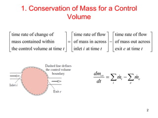
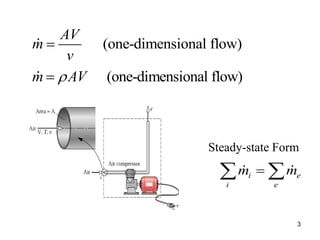
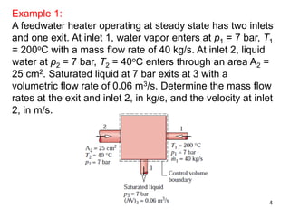
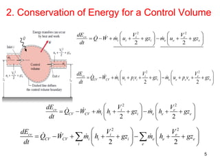
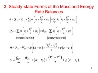
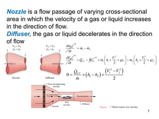
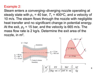
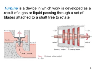

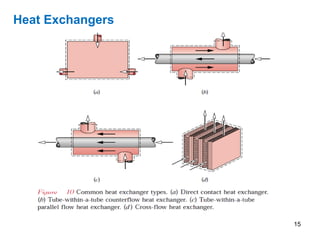
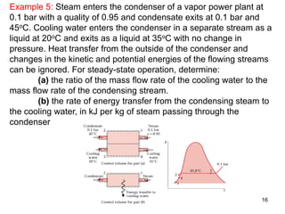

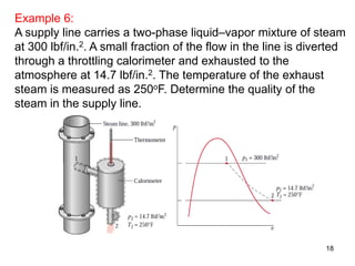
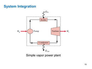

This document provides an overview of control volume analysis using energy concepts. It discusses key concepts like conservation of mass and energy for a control volume. It presents the steady state forms of the mass and energy rate balances. Examples are provided to demonstrate applying these concepts to devices like nozzles, turbines, compressors, heat exchangers, and throttling devices. The overall summary is that control volume analysis using energy concepts allows analyzing thermodynamic systems by applying conservation of mass and energy to a defined control volume.