Download to read offline
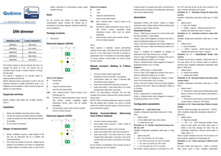

This document provides information about a Z-Wave DIN dimmer module used for dimming lights and fans. The module can be controlled through a Z-Wave network or wall switch. It measures power consumption and supports connecting a temperature sensor. The module is small, designed to mount on a DIN rail, and can act as a repeater to improve the Z-Wave network range. Technical specifications, diagrams, instructions and configuration parameters are provided.