Downloaded 2,111 times
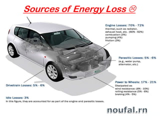
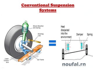
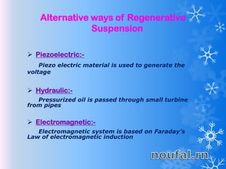
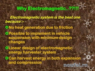
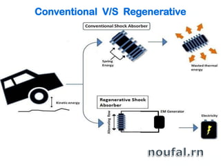
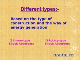
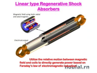
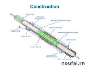
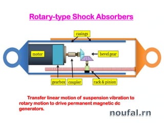

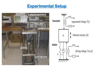
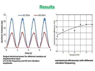

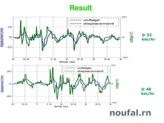


This document discusses electromagnetic regenerative shock absorbers that can recover vibration energy from a vehicle's suspension that is normally lost. It describes how conventional suspension systems waste much of a vehicle's energy. Electromagnetic regenerative shock absorbers use Faraday's law of induction to generate electricity from the relative motion between magnetic fields and coils during suspension movement. They can harvest energy in both compression and rebound strokes. The document outlines different types of regenerative shock absorbers and explains the construction, working, advantages, and limitations of linear and rotary electromagnetic designs. Experimental testing showed increased fuel efficiency and power generation from vehicle road tests.


![Regenerative Suspension System-Project Review [Compatibility Mode]](https://cdn.slidesharecdn.com/ss_thumbnails/121f9b0b-165f-4cfd-8bdc-b033b6265eb0-161123182304-thumbnail.jpg?width=640&height=640&fit=bounds)


